
SAND2019-12009 O
Unlimited Release
FEDERAL RADIOLOGICAL
MONITORING AND ASSESSMENT CENTER
FRMAC FLY AWAY LABORATORY MANUAL
The Federal Manual for Performing Laboratory Analysis
during a Radiological Emergency
October, 2019
SAND2019-12009 O
Unlimited Release
FRMAC Fly Away Laboratory Manual ii
Prepared by
Sandia National Laboratories
Albuquerque, New Mexico 87185 and Livermore, California 94550
Sandia National Laboratories is a multimission laboratory managed and operated by National Technology & Engineering Solutions of Sandia,
LLC, a wholly owned subsidiary of Honeywell International Inc., for the U.S. Department of Energy’s National Nuclear Security Administration
under contract DE-NA0003525.

SAND2019-12009 O
Unlimited Release
FRMAC Fly Away Laboratory Manual iii
FRMAC Fly Away Laboratory Manual
Elliott J. Leonard
FRMAC Laboratory Analysis FAL Supervisor
Sandia National Laboratories
Albuquerque, NM
Phil Torretto
FRMAC Laboratory Analysis Working Group
Lawrence Livermore National Laboratory
Livermore, CA
Arthur Shanks Jr., Technical Chairman
FRMAC Laboratory Analysis Working Group
Sandia National Laboratories
Albuquerque, NM
This work was supported by the U.S. Department of Energy, National Nuclear Security Administration
Nevada Operations Office, under Contract No. DE-AC08-96NV11718.
FRMAC is an acronym for Federal Radiological Monitoring and Assessment Center.

SAND2019-12009 O
Unlimited Release
FRMAC Fly Away Laboratory Manual iv
DISCLAIMER
This report was prepared as an account of work sponsored by an agency of the United States Government.
Neither the United States Government nor any agency thereof, nor any of their employees, nor any of their
contractors, subcontractors or their employees, makes any warranty, express or implied, or assumes any
legal liability or responsibility for the accuracy, completeness, or any third party’s use or the results of such
use of any information, apparatus, product, or process disclosed, or represents that its use would not
infringe privately owned rights. Reference herein to any specific commercial product, process, or service by
trade name, trademark, manufacturer, or otherwise, does not necessarily constitute or imply its
endorsement, recommendation, or favoring by the United States Government or any agency thereof or its
contractors or subcontractors. The views and opinions of authors expressed herein do not necessarily state
or reflect those of the United States Government or any agency thereof.
AVAILABILITY
Available for sale to the public, in paper, from:
U.S. Department of Commerce
National Technical Information Service
5285 Port Royal Road
Springfield, VA 22161
phone: 800.553.6847
fax: 703.605.6900
email: [email protected]
online ordering: http://www.ntis.gov/ordering.htm
Available electronically at http://www.osti.gov/bridge
Available for a processing fee to U.S. Department of Energy
and its contractors, in paper, from:
U.S. Department of Energy
Office of Scientific and Technical Information
P.O. Box 62
Oak Ridge, TN 37831-0062
phone: 865.576.8401
fax: 865.576.5728
email: [email protected]
Also available at the FRMAC website,
https://www.nnss.gov/pages/programs/FRMAC/FRMAC_DocumentsManuals.html
SAND2019-12009 O
Unlimited Release
FRMAC Fly Away Laboratory Manual v
Preface
This manual was written for those personnel who respond to a radiological/nuclear incident that
will be called upon to provide proper analysis support. Overall, this manual provides general
guidance and some specific diagrams and forms. However, it is understood that site- and event-
specific operational decisions and procedures may need to be modified at the time of an
emergency event. This manual is intended to provide guidance for Fly Away Laboratory
personnel without limiting FRMAC’s ability to integrate the work with other partners or
stakeholders.
The NNSA/NSO has the overall responsibility for maintaining the master copy of all FRMAC
manuals. Please provide comments on this manual to:
U.S. Department of Energy
National Nuclear Security Administration
Nevada Site Office
Attn: FRMAC Program Manager
P.O. Box 98518
Las Vegas, Nevada 89193-8518
Acknowledgments
Creation of the FRMAC Fly Away Laboratory (FAL) Manual was a major undertaking to which
many people contributed. Special thanks go to Elliott Leonard Sean Fournier and Ken Sansone
of Sandia National Laboratories; Manuel Franco Jr. and Luis Valdivia of Apple One; Wendy
Pemberton of the Remote Sensing Laboratory; and Richard Bibby, Cynthia Conrado, Jay Dixon,
Mark Johnson and Phil Torretto of Lawrence Livermore National Laboratory who developed and
organized much of the material in this revision.
SAND2019-12009 O
Unlimited Release
FRMAC Fly Away Laboratory Manual vi
Acronyms and Abbreviations
ADC
Analog to Digital Converter
ALARA
As Low As Reasonably Achievable
ARF
Analysis Request Form
ARMS
Asset Readiness Management System
CM
Consequence Management
CMHT
Consequence Management Home Team
CMRT I
Consequence Management Response Team phase I
DOE
Department of Energy
DQO
Data Quality Objectives
EOTA
Emergency Operations Training Academy
FAL
Fly Away Laboratory
FRMAC
Federal Radiological Management Assessment Center
FWHM
Full Width at Half Maximum
GAB
Gross Alpha/Beta
HPGe
High Purity Germanium
HVPS
High Voltage Power Supply
ICS
Incident Command System
LAN
Local Area Network
LLD
Lower Level Discriminator
LSC
Liquid Scintillation Counting
MCA
Multi-Channel Analyzer
MQO
Measurement Quality Objectives
NIST
National Institute of Standards and Technology
NNSA
National Nuclear Security Administration
NSO
Nevada Site Office
QA
Quality Assurance
QC
Quality Control
RSL
Remote Sensing Laboratory
SCF
Sample Control Form
SNL
Sandia National Laboratories
SOP
Standard Operating Procedure
USB
Universal Serial Bus
SAND2019-12009 O
Unlimited Release
FRMAC Fly Away Laboratory Manual vii
Table of Contents
Revision Date
Section 1. Introduction…………………………...............………………………………..
1-1
11/13
Section 2. Roles and Responsibilities......................................…………….....…….
2-1
11/13
Section 3. Quality Control..…………………………………………………….............….
3-1
8/19
Section 4. Sample Control................................................................…….....……….....
4-1
8/19
Section 5. Logistics................................................................…………………......……...
5-1
11/13
Section 6. Gamma Spectroscopy Procedures....……………………..........……….
6-1
8/19
Section 7. iSOLO Operations...........……………………………………............………
7-1
8/19
Section 8. Analytical Balance Use..............................................................................
8-1
11/13
Section 9. Data Handling and Verification/Validation...................................
9-1
11/13
List of Appendices
Appendix A: iSOCS Geometry Composer Tutorial...........……..…………….
A-1
11/13
Appendix B: Fly Away Laboratory Forms.……………………………..........…….
B-1
8/19
SAND2019-12009 O
Unlimited Release
FRMAC Fly Away Laboratory Manual viii
This page is intentionally left blank

August 2019 Section 1: Introduction
FRMAC Fly Away Laboratory Manual 1-1
Section 1: Introduction
When the FRMAC responds to a radiological/nuclear incident, monitoring, sampling, and
radioanalytical support will arrive from several different sources. The responders providing this
support will, likely, have received varying levels of training and will have experience with a
variety of monitoring, sampling, and radioanalytical equipment and procedures. It is important
that an acceptable and established set of standard operating procedures (SOPs) be followed by all
personnel having responsibilities for processing and analyzing samples during the emergency.
Overall, this manual provides general guidance and some specific diagrams and forms. However,
it is understood that site- and event-specific operational decisions and procedure parameters will
need to be established and documented at the time of an emergency.
The purpose of this manual is to provide guidance to Fly Away Laboratory (FAL) personnel
responsible for the analysis of time sensitive radiological samples. With proper training,
preparation, and equipment, FAL personnel will be able to quickly provide reliable results for
radiological samples that have been deemed immediately important to the health and safety of
emergency response personnel as well as the general public. Upon deployment of the FRMAC,
the Consequence Management Response Team will have set up shelter and workspace for the
FAL. Equipment load-outs have been designed to be able to be shipped via commercial airlines
or DOE aircraft. In this way, the FAL will most likely be the first field laboratory on-site and
will be crucial in the rapid analysis of emergency-phase samples.
It is the responsibility of CMRT personnel to deploy the laboratory specific-equipment and begin
operations upon arrival. This manual will provide guidance as to how to set up an efficient
laboratory working area. However, it will be up to the FAL personnel to be able to adapt to any
situation that may come up during an event. Although a part of the FRMAC, the FAL will be
acting as a laboratory entity with respect to the other FRMAC functions (Laboratory Analysis,
Assessment, Monitoring and Sampling, Health and Safety) and will take direct instruction from
the FAL Manager and FRMAC Laboratory Analysis personnel.
Work in the Fly Away Laboratory may require working outdoors in possibly extreme conditions.
Watch for snakes, rodents, insects, and other potentially hazardous flora or fauna. Be aware of
changing weather conditions, and immediately follow all orders regarding the protection of your
health and safety.

August 2019 Section 1: Introduction
FRMAC Fly Away Laboratory Manual 1-2
This page is intentionally left blank

August 2019 Section 2: Roles and Responsibilities
FRMAC Fly Away Laboratory Manual 2-1
Section 2: Roles and Responsibilities
Table of Contents
2.1 Position Descriptions ....................................................................................................................... 2
2.1.1 Fly Away Laboratory Manager .......................................................................................................... 2
2.1.2 Fly Away Laboratory Analst ............................................................................................................... 3
2.2 Required Training Matrix ................................................................................................................. 5
Tables
Table 2.1: FAL Personnel Training Requirements .................................................................................... 5

August 2019 Section 2: Roles and Responsibilities
FRMAC Fly Away Laboratory Manual 2-2
2.1 Position Descriptions
2.1.1 Fly Away Laboratory Manager
The FRMAC Fly Away Laboratory (FAL) Manager maintains close coordination with the
FMRAC Laboratory Analysis Manager. The FAL Manager communicates and interfaces with
FAL personnel to ensure that the FAL’s resources are adequately and correctly used.
Deploys in Phase I – No
Deploys in Phase II - Yes
2.1.1.1 Duties and Responsibilities
• Maintain a general working knowledge and understanding of FRMAC missions,
capabilities, objectives, and procedures
• Maintain expert working knowledge and experience in radiochemical analytical
methods, laboratory operations, laboratory QA/QC, and environmental
radiochemistry
• Maintain detailed knowledge, expertise, and proficiency with the FRMAC Fly Away
Laboratory Manual, laboratory sample tracking, and data analysis software
• Communicate sample priorities from the Laboratory Analysis Group to the FAL Staff
• Communicate analytical capability and capacity of the FAL to the FRMAC
Laboratory Analysis Manager and FRMAC Laboratory Analysis Deputy Manager
• Participate in calls, meetings, and conferences of the Laboratory Analysis Working
group during an active event
• Act as the final approval in the quality assurance data review process for all samples
analyzed by the FAL
2.1.1.2 Organization and Communications
• RECEIVES DIRECTION FROM:
o FRMAC Laboratory Analysis Manager
• WORKS WITH:
o FRMAC Laboratory Analysis Manager
o FRMAC Deputy Laboratory Analysis Manager
o FRMAC Laboratory Analysis Personnel
o FAL Laboratory Staff
• PROVIDES DIRECTION TO:
o FAL Laboratory Staff
2.1.1.3 Skills and Knowledge
• Maintain a general working knowledge and understanding of FRMAC missions,
capabilities, objectives, and procedures
• Maintain expert working knowledge and experience in radioanalytical methods,
laboratory operations, laboratory QA/QC, and environmental radiochemistry

August 2019 Section 2: Roles and Responsibilities
FRMAC Fly Away Laboratory Manual 2-3
• Demonstrated extensive knowledge and experience in laboratory and environmental
radiochemistry methods
• Working knowledge and experience with DQOs, analytical methods, minimum
detectable activity (MDA) calculations, and quality assurance procedures
• Working knowledge and experience with DRLs, AALs, EPA PAGs and FDA
intervention levels
• Radiation Worker I trained
• Successful completion of all training identified in Asset Readiness and Management
System (ARMS)
• Authorized for deployment
2.1.1.4 Education and Experience
• Active participation in an official FRMAC exercise as part of the FAL team
• Minimum of 3 years of experience managing a radioanalytical laboratory and
managing radioanalytical analyses
2.1.1.5 Physical Demands and Requirements
• Able to adapt and work in austere living conditions
• Able to work long hours in possibly stressful, urgent situations
• Able to adapt and work in extreme temperature and weather conditions
2.1.2 Fly Away Laboratory Analst
The FRMAC Fly Away Laboratory (FAL) Analyst is responsible for receiving, inspecting, and
logging in samples that have been submitted to, and screened by Health and Safety personnel.
The FAL Analyst place samples in the staging area and assists in preparing these samples for
analysis by completing the necessary documentation. Once documentation is complete, the FAL
Analyst places the samples into proper storage. The FAL Analysts are required to perform
requested analyses on samples received. This task includes sample preparation, detector setup,
sample counting, data analysis, and review.
Deploys in Phase I – No
Deploys in Phase II - Yes
2.1.2.1 Duties and Responsibilities
• Maintain a general working knowledge and understanding of FRMAC missions,
capabilities, objectives, and procedures
• Maintain detailed knowledge and familiarity with the FRMAC Fly Away Laboratory
Manual and sample control and data analysis software
• Review, validate, and sign chain of custody documentation (Analysis Request
Forms).
• Log samples into the FAL sample tracking system
• Record sample tracking information and prepare necessary paperwork
• Remain cognizant of contamination control procedures during all sample control and
handling activities

August 2019 Section 2: Roles and Responsibilities
FRMAC Fly Away Laboratory Manual 2-4
• Perform sample preparation
• Perform Gamma spectral analysis and detector efficiency modeling using vendor
software
• Perform liquid scintillation analysis
• Perform gross alpha/beta analysis
• Perform data report generation using custom software developed for the FAL
• Review laboratory results for errors
• Maintain instrumentation in working condition and calibration
• Perform routine quality control schedules for each instrument
• Troubleshoot hardware and software issues relevant to radiation detection
instrumentation
2.1.2.2 Organization and Communications
• RECEIVES DIRECTION FROM:
o FRMAC FAL Manager
• WORKS WITH:
o FRMAC Laboratory Analysis Personnel
o FRMAC FAL Manager
• PROVIDES DIRECTION TO:
o N/A
2.1.2.3 Skills and Knowledge
• Maintain a general working knowledge and understanding of FRMAC missions,
capabilities, objectives, and procedures
• Maintain working knowledge and experience in radioanalytical methods, laboratory
operations, laboratory QA/QC, and environmental radiochemistry.
• Demonstrated knowledge and experience in laboratory and environmental
radiochemistry
• Radiation Worker I trained
• Successful completion of all training identified in Asset Readiness and Management
System (ARMS)
• Authorized for deployment
2.1.2.4 EDUCATION AND EXPERIENCE
• Active participation in an official FRMAC exercise as part of the FAL team
• Minimum of 1 year experience performing analyses using Gamma Spectroscopy,
Alpha/Beta counting, or Liquid Scintillation counting, or has completed all of the
required training and works with a more experienced FAL Analyst
2.1.2.5 PHYSICAL DEMANDS AND REQUIREMENTS
• Able to adapt and work in austere living conditions
• Able to work long hours in possibly stressful, urgent situations
• Able to adapt and work in extreme temperature and weather conditions

August 2019 Section 2: Roles and Responsibilities
FRMAC Fly Away Laboratory Manual 2-5
2.2 Required Training Matrix
Table 2.1: FAL Personnel Training Requirements
Description
Frequency
Fly Away Lab
Manager
Laboratory
Staff
ICS 100- Introduction to ICS
1 time
X
X
ICS-200 – ICS for Single resources and Initial
Action Incidents
1 time
X
X
ICS-800.b National Response Framework
(NRF)Introduction.
1 time
X
X
DOE Rad Worker II (or equivalent)
Current
X
X
FAL -100 – FAL Field Logistics
3 yrs
X
X
FAL-200 – FAL Gamma Spectroscopy
Operations
3 yrs
X
X
FAL-300 – FAL Gross Alpha/Beta Operations
3 yrs
X
X
FAL-600 – FAL Gamma Spectrometer
Maintenance
3 yrs
X
FAL-700- FAL Gross Alpha/Beta Routine
Maintenance
3 yrs
X

August 2019 Section 2: Roles and Responsibilities
FRMAC Fly Away Laboratory Manual 2-6
This page is intentionally left blank

August 2019 Section 3: Quality Control
FRMAC Fly Away Laboratory Manual 3-1
Section 3: Quality Control
Table of Contents
3.1 Introduction ..................................................................................................................................... 2
3.2 QC Sample Assignment and Preparation ......................................................................................... 2
3.3 QC Sample Processing ...................................................................................................................... 2
3.3.1 Quality Control Samples .................................................................................................................... 2
3.3.2 Blank Samples ................................................................................................................................... 2
3.3.3 Laboratory Control Samples (LCS) ..................................................................................................... 3

August 2019 Section 3: Quality Control
FRMAC Fly Away Laboratory Manual 3-2
3.1 Introduction
The purpose of processing quality control (QC) samples is to provide continuing assurance of
laboratory performance and to make internal laboratory performance audits more effective.
Positive controls (laboratory control sample [LCS], blind quality control sample [BQC], and
matrix spike samples) serve as a monitor of the overall accuracy of all steps in the analysis,
including sample preparation. Negative controls (matrix blanks, backgrounds, and reagent
blanks) are used to assess the existence and magnitude of contamination problems as well as
natural background contributions. If problems with any QC sample exist, all data associated with
the batch shall be carefully evaluated to determine whether the sample results are adversely
affected.
Acceptance limits are predetermined and set in the software for each piece of instrumentation.
These values are set to typical acceptance limits for laboratory-grade instrumentation. However,
due to the variability in the environment, the Fly Away Laboratory Manager has the authority to
alter acceptance limits based on the situation.
3.2 QC Sample Assignment and Preparation
At a minimum, a set of QC samples should consist of one positive control and one negative
control. Assign a set of QC samples to each preparation batch of samples. The minimum number
of QC samples shall be one set included in each batch, where the batch does not exceed a total of
20 samples. If reasonable, positive controls should have activity concentrations appropriate for
the required measurement quality objectives (MQOs). Typically, LCS, BQCs, and/or matrix
spike sample concentrations should be at least 10 times the required critical level (L
c
) if possible.
3.3 QC Sample Processing
3.3.1 Quality Control Samples
QC samples serve as indicators of method performance. If the QC results fall outside of the
acceptance limits, all data associated with the batch shall be carefully evaluated to determine if
the samples were compromised, and appropriate corrective actions shall be taken. Reprocess any
samples that are suspected to be compromised. If reprocessing is not possible, contact the FAL
Manager. Reprocesses are documented in the case file associated with the group for samples in
question. Suspect results are qualified on the customer report. Instrument QC checks should be
performed routinely to ensure the instrument has not been contaminated and is operating within
control. Appropriate corrective actions (adjustments to the instrumentation, decontamination,
and/or recalibration) shall be performed if an instrument is determined to be operating outside of
tolerance limits. Record any corrective actions in the instrument’s logbook.
3.3.2 Blank Samples
Blank analysis results are assessed to determine the existence and magnitude of contamination
problems. The criteria for evaluation of blanks apply to any blank associated with the samples.
Review the results of the blanks. If the blank results fall outside the appropriate tolerance limits,
all data associated with the batch shall be carefully evaluated to determine whether the samples
were contaminated. Reprocess any samples that are suspected to be contaminated. If

August 2019 Section 3: Quality Control
FRMAC Fly Away Laboratory Manual 3-3
reprocessing is not possible, contact the FAL Manager. Document reprocesses in the batch file
associated with the group of samples in question. Qualify suspect results are on the customer
report.
3.3.3 Laboratory Control Samples (LCS)
The LCS serves as a monitor of the overall accuracy and performance of all steps in the analysis,
including the sample preparation. The LCS should contain an activity greater than 10 times the
radionuclide’s critical level, if possible. All LCS results should fall within the pre-established
tolerance limits, if applicable. If the LCS recoveries fall outside the appropriate tolerance limits,
all data associated with the batch shall be carefully evaluated to determine whether the actual
sample results were affected, and appropriate corrective actions shall be taken. Reprocess any
samples that are suspected to be affected. If reprocessing is not possible, contact the FAL
Manager.

August 2019 Section 3: Quality Control
FRMAC Fly Away Laboratory Manual 3-4
This page is intentionally left blank

August 2019 Section 4: Sample Control
FRMAC Fly Away Laboratory Manual 4-1
Section 4: Sample Control
Table of Contents
4.1 Introduction ..................................................................................................................................... 2
4.2 Setup of the Sample Control Staging Area ...................................................................................... 2
4.3 Sample Login and Tracking Process ................................................................................................. 3
4.3.1 Samples for Routine Analysis ............................................................................................................ 3
Figures
Figure 4.1: Example - Sample Control Staging Area Recommended Setup ............................................. 3
Figure 4.2: Tracking Database Main Menu .............................................................................................. 4

August 2019 Section 4: Sample Control
FRMAC Fly Away Laboratory Manual 4-2
4.1 Introduction
Upon deployment of the FRMAC Fly Away Laboratory, CMRT personnel will have deployed
the materials for an appropriate staging area. This section of the manual outlines the
recommended setup of the sample control area, where samples that are collected in the field will
be brought and logged into the FAL system. This section also outlines the logistical requirements
of the sample tracking process.
Sample tracking can be handled with the FAL Login excel spreadsheet. At the start of an event,
open the FAL LOGIN TEMPLATE.XLTM located on the sample login computer, or on the shire
FAL SharePoint. Fill out the header section Event Name and Start Date. Save the with the
filename that matches the event name.
4.2 Setup of the Sample Control Staging Area
There likely will be adequate tables and chairs to establish a sample control staging area onsite.
This area includes designated areas for temporary storage of samples received, a computer login
station, and areas for samples that require analysis, organized by the type of analysis requested .
The designated storage areas are marked off with tape and labeled with a marker.
Refer to Figure 4.1 for an example of the staging area layout.
Computer
Login
Station
Gamma
Spectroscopy
Samples
Gross
Alpha/Beta
Samples
Shipment
surveys
Completed
samples to
be returned
to FRMAC

August 2019 Section 4: Sample Control
FRMAC Fly Away Laboratory Manual 4-3
Figure 4.1: Example - Sample Control Staging Area Recommended Setup
It is recommended to set up the sample control staging area in such a way that it is clear which
samples have been logged into the system and are ready for analysis. All samples must be
processed through such a staging area before entering the laboratory area. When samples
contain significant quantities of radioactive material, be sure to align any staging or storage areas
to keep the dose to FAL personnel as low as reasonably achievable (ALARA) and ensure that the
instrument backgrounds are not affected by the flux of samples in and out of the storage area.
The use of temporary shielding or out-of-the-way storage areas may be required. Temporary
shield can be constructed using empty equipment boxes or coolers filled with water. You may
choose to request a radiological survey to be performed in this staging area by FRMAC Health
and Safety Radiological Control Technicians to be sure. You may also want to rerun
backgrounds on the FAL instrumentation when radiological conditions change in the
storage/staging area.
4.3 Sample Login and Tracking Process
4.3.1 Samples for Routine Analysis
Routinely, samples are brought by FRMAC Laboratory Analysis personnel to the Fly Away
Laboratory sample control staging area. Each group of samples has an Analysis Request Form
(ARF). This ARF includes all the required information to perform the analysis of the sample(s).
Each sample in a batch has a unique number associated with it, known as a “Sample Control
Form (SCF) or Sample number.” Upon receipt of a batch of samples, FAL Staff complete the
following:
1. The samples have been screened for external removable contamination at the hotline by a
FRMAC Radiation Control Technologist (RTC). If a breach in the contaminant is
suspected immediately contact FRMAC Heath and Safety for a contamination screening
and keep everyone in the area to avoid the spread of contamination.
3.
2. Confirm that all the samples listed on the ARF are included in the shipment to the staging
area.
4.
3. Have the courier of the samples sign the chain-of-custody line on the ARF indicating that
the samples are now leaving their possession.
5.
4. Sign the chain-of-custody line on the ARF indicating that you (FRMAC Fly Away
Laboratory) are now in custody of the samples. If the sample is contaminated, contact the
FAL Manager for guidance.
6.
5. Place the samples in the designated drop-off point.
7.

August 2019 Section 4: Sample Control
FRMAC Fly Away Laboratory Manual 4-4
6. Log the sample into the FAL login excel sheet created for the current event, as in Figure
4.2.
Figure 4.2: Tracking Database Main Menu
7. Enter the sample information by filling out the form:
• SCF number in the first column (A),
• ARF number in the second column (B),
• requested Analysis in the third column (C),
• sample matrix in the fourth column (D),
• place an “x” in the Pending Analysis column (E),
• select the priority in eight column (H),
• and optionally enter any pertinent comments in the ninth column (I).
8. The 10
th
Column (J) has controls to make entering the sample data easier. Double click
on the cell to perform the operation in that cell. For an ARF with many samples the COPY
ROW control followed by the excel fill down operation can be used in increase efficiency.
8.
9. Place each sample in the appropriate storage location next to the computer station. If the
samples are high activity samples, ask the FAL manager for further assistance. As
samples are picked up from the storage location, change the status of the sample in the
spreadsheet to “Pending Analysis” by placing an “x” in the Column E for that sample.

August 2019 Section 4: Sample Control
FRMAC Fly Away Laboratory Manual 4-5
9.
10. Upon completion of the analysis and review of the results, change the status of the
sample to “Reported” in by placing an “x” in the Column F for that sample. Place
completed samples in the “Return to FRMAC” location. When the courier arrives to pick
up samples, transfer the chain of custody of the samples back to FRMAC by signing the
appropriate chain of custody line on the ARF. Be sure to have the courier sign as
accepting possession of the sample(s). If possible, make a copy of the ARF, retain the
copy, and provide the original ARF to the courier.
10.
4.3.2 Samples for Non-routine Analysis
There is potential in the FAL to receive samples for shipping screening or from another
participating agency. Samples without an accompanying ARF fall within the scope of this
section. As such they will not have the typical chain of custody on the ARF nor the guarantee of
contamination and hazard screening.
1. Ensure that before receiving samples there has been a hazards screen for excess activity
on the sample and removable contamination. The results of the screen shall be
commutated to the FAL personnel in writing with the signature of the certified
Radiological Control Technician who performed the screening.
11.
2. Confirm that all the samples have a chain-of-custody (COC) and they are all listed on the
form.
12.
3. Have the courier of the samples sign the line the COC form indicating that the samples
are now leaving their possession.
13.
4. Sign the line the COC form (FRMAC Fly Away Laboratory) are now in custody of the
samples.
14.
5. Place the samples in the designated drop-off point.
6. Log the sample into the FAL login excel sheet created for the current event, as in Figure
4.2.
7. Enter the sample information by filling out the form:
• A unique identifying number either provided by the customer or if the sample is for
shipping screening number prepended with PRCL then a number in the first column
(A),
• A unique number grouping the samples or “Shipping” if the sample is for shipping
screening in the second column (B),
• requested Analysis in the third column (C),
• sample matrix in the fourth column (D),
• place an “x” in the Pending Analysis column (E),
• select the priority in eight column (H),
• and optionally enter any pertinent comments in the ninth column (I).

August 2019 Section 4: Sample Control
FRMAC Fly Away Laboratory Manual 4-6
8. The 10
th
Column (J) has controls to make entering the sample data easier. Double click
on the cell to perform the operation in that cell. For an ARF with many samples the COPY
ROW control followed by the excel fill down operation can be used in increase efficiency.
15.
9. Place each sample in the appropriate storage location next to the computer station. If the
samples are high activity samples, ask the FAL manager for further assistance. As
samples are picked up from the storage location, change the status of the sample in the
spreadsheet to “Pending Analysis” by placing an “x” in the Column E for that sample.
16.
10. Upon completion of the analysis and review of the results, change the status of the
sample to “Reported” in by placing an “x” in the Column F for that sample. Place
completed samples in the “Return to FRMAC” location. When the courier arrives to pick
up samples, transfer the chain of custody of the samples back to the customer by signing
the appropriate line on the COC. Be sure to have the courier sign as accepting possession
of the sample(s). If possible, make a copy of the COC, retain the copy, and provide the
original COC to the courier.

August 2019 Section 5: Logistics
FRMAC Fly Away Laboratory Manual 5-1
Section 5: Logistics
Table of Contents
5.1 Fly Away Laboratory Overview ........................................................................................................ 2
5.2 Equipment Load-Out ........................................................................................................................ 2
5.3 On-Site Equipment Needs ................................................................................................................ 2
5.4 Safety Hazards and Required Facility ............................................................................................... 3
5.5 Communication Requirements ........................................................................................................ 3
Figures
Figure 5.1: Fly Away Laboratory Floor Diagram ........................................................................................ 4

August 2019 Section 5: Logistics
FRMAC Fly Away Laboratory Manual 5-2
5.1 Fly Away Laboratory Overview
The DOE FAL is an asset capable of transporting its equipment via commercial, contract,
military, or charter aircraft. The laboratory equipment is located at the Remote Sensing
Laboratory (RSL) in Nevada and deployed as part of CMRT I. FAL personnel shall be
responsible for developing instrument capabilities, ensuring personnel are trained on the
calibration and use of the instrumentation, and ensuring that all equipment is available for
immediate deployment when called upon.
Deployed equipment is capable of analyzing samples for alpha-, beta- , and gamma-emitting
radionuclides.. They can process all types of samples including, but not limited to: ground
deposition, air filters, swipes, and liquid samples. However, no sample preparation capability is
available in the FAL and samples must be analyzed in the containers in which they are collected
except for air filters and smears which can be carefully removed from their container and placed
in the counting instrument.
.
The equipment is “exercised” regularly to ensure that the equipment is ready to be used on short
notice, and that personnel maintain training on the equipment.
Figure 5.1 provides an example layout of the Fly Away Laboratory processes. Due to the
proximity of the counting equipment, some analyses may be impacted by the samples submitted
to the FAL for analysis. For example, if a high activity sample is received for iSOLO analysis,
the background counts of the gamma spectroscopy units may be impacted. It is important to be
aware of this and make use of shielding and recounting of backgrounds to account for it.
5.2 Equipment Load-Out
If possible, a minimum of two of each of the following instruments will be maintained at the
RSL:
• Gamma Detector, Associated Computers, Software, Printers, and Standard Sources
• Radon Compensating Alpha/Beta Counter (iSOLO™), Associated Computer,
Software, Printers, and Standard Sources
NOTE: It is acceptable to have a single network printer for the entire Fly Away Laboratory.
5.3 On-Site Equipment Needs
The following are the on-site equipment needs:
• Six 6-ft tables
• Two 4-ft tables
• Six chairs
• Sample Storage containers
• Refrigeration capabilities (if required)

August 2019 Section 5: Logistics
FRMAC Fly Away Laboratory Manual 5-3
5.4 Safety Hazards and Required Facility
• Handling of radioactive sources and samples will be necessary. One should keep
radiation exposure as low as reasonably achievable (ALARA) by minimizing the
handling of sources and sample material. Care shall be exercised in handling samples
according to their associated hazards, whether they are a biological, chemical, and/or
radiological.
• When the potential for external contamination exists on the sample container(s),
protective gloves shall always be worn while handling the samples.
• The operation of a germanium detector requires a high voltage of 3 to 5 KV at a few
mA. Caution must be exercised to avoid touching any high voltage connections.
Much of the FAL equipment operates on Li-ion batteries. Inspect all batteries prior to
use for cracks, swelling, and signs of leakage. Dispose of damaged batteries
appropriately and replace with equivalent equipment.
•
• Work in the Fly Away Laboratory may require working outdoors in possibly extreme
conditions. Watch for snakes, rodents, insects, and other potentially hazardous flora
or fauna. Be aware of changing weather conditions and immediately follow all orders
regarding the protection of your health and safety. Care should be taken when lifting
heavy weights to avoid personal injuries.
• The following are facility requirements:
o Climate controlled 150 ft
2
lockable building/tent
o When not performing 24hr operations, a locked facility or security force is
required to protect the equipment when not in use.
o Sample storage area/tent (size dependent on the size of the incident)
o 110V power with a minimum of 12 outlets
o Generator fueled for 24 hour operations in the event of an extended power
outage
o Located near Sample Control Tent (desirable)
5.5 Communication Requirements
The following are the communication requirements:
• Email access to forward electronic results
• Internet access
• Wireless hotspot
• Telephone and fax line

August 2019 Section 5: Logistics
FRMAC Fly Away Laboratory Manual 5-4
Figure 5.1: Fly Away Laboratory Floor Diagram
Gamma Spec
Gamma Spec
iSolo Sample Screening
Work
Space
Work
Space
Sample
Holding
Area
iSolo

August 2019 Section 6: Gamma Spectroscopy Procedures
FRMAC Fly Away Laboratory Manual 6-1
Section 6: Gamma Spectroscopy Procedures
Table of Contents
6.1 Purpose ............................................................................................................................................ 3
6.2 Scope ................................................................................................................................................ 3
6.3 Summary of Method ........................................................................................................................ 3
6.4 Apparatus and Materials ................................................................................................................. 3
6.5 Routine Operations .......................................................................................................................... 4
6.5.1 On-site Setup of the FALCON™ ......................................................................................................... 4
6.5.2 Initializing the High Voltage .............................................................................................................. 7
6.5.3 Quality Control (QC) Check ............................................................................................................... 8
6.5.4 Performing a Background ................................................................................................................. 9
6.5.5 Gamma Library Creation ................................................................................................................. 10
6.5.6 Sample Analysis ............................................................................................................................... 11
6.5.7 Performing a Background Check (Blank) ......................................................................................... 14
6.5.3 ISOCS Check .................................................................................................................................... 15
6.6 Non-Routine Operations ................................................................................................................ 16
6.6.1 Calibration ....................................................................................................................................... 16
6.6.2 Initial Setup from Factory (New FALCON™ Unit) ............................................................................ 22
6.6.3 Acceptance Testing ......................................................................................................................... 38
Figures
Figure 6.1: FALCON 5000™ Power Setup .................................................................................................. 5
Figure 6.2: FALCON 5000™ Control/Display Panel ................................................................................... 5
Figure 6.3: FALCON 5000™ Battery ports and connectors....................................................................... 6
Figure 6.4: FALCON 5000™ Control/Display Panel ................................................................................... 6
Figure 6.6: Energy Calibration Curves Window Showing Peaks .............................................................. 18
Figure 6.7: Energy Calibration Curves Window Showing the Shape Curve ............................................ 18
Figure 6.8: Placement of Foam Spacers to Avoid Damage to Connector .............................................. 24
Figure 6.9: Access to the RS232 Port underneath the Display/Control Panel ....................................... 25
Figure 6.10: Example of the HyperTerminal .......................................................................................... 26
Figure 6.11: Example of the detector.txt File ......................................................................................... 37
Figure 6.12: Example of Data To Be Copied to detector.txt on the Machine ........................................ 38

August 2019 Section 6: Gamma Spectroscopy Procedures
FRMAC Fly Away Laboratory Manual 6-2
Tables
Table 6.1: Calibration Descriptions ........................................................................................................ 12
Table 6.2: Routine Analysis Required Sample Information.................................................................... 13
Table 6.3: Suggested Calibration Values ................................................................................................. 17
Table 6.4: FALCON 5000™ MCA Input Definition (MID) Settings Part 1 ................................................ 30
Table 6.5: FALCON 5000™ MCA Input Definition (MID) Settings Part 2 ................................................. 31
Table 6.6: QC QAF File Settings CNTRD and FWHM ............................................................................... 32
Table 6.7: QC QAF File Settings for DCA ................................................................................................. 33
Table 6.8: BKG QAF File Settings ............................................................................................................ 33
Table 6.9: ISX/LCS QAF File Settings ....................................................................................................... 33
Table 6.10: Required Executable Files ................................................................................................... 35
Table 6.11: Required CAM files .............................................................................................................. 35
Table 6.12: Required Template (.tpl) Files ............................................................................................. 35
Table 6.13: Required Calibration Files ................................................................................................... 36
Table 6.14: Example iSOCS™ Characterization Files .............................................................................. 37

August 2019 Section 6: Gamma Spectroscopy Procedures
FRMAC Fly Away Laboratory Manual 6-3
6.1 Purpose
The purpose of this procedure is to describe the proper use of the FALCON™ portable gamma
spectroscopy system. The following activities are documented in this procedure:
• On-Site Setup of the FALCON™
• Quality Control
• Sample Preparation
• Sample Analysis
• Calibration of the FALCON™
• Maintenance and Acceptance Testing
6.2 Scope
The FALCON™ 5000 is an electronically-cooled high purity germanium detector. This highly
mobile portable gamma spectrometer can rapidly provide nuclide identification and
quantification for gamma emitting isotopes in calibrated geometries. iSOCS™ calibration files
can be quickly and easily generated in the field for many geometries, freeing the user from the
requirement of having calibrated geometries prior to analysis. This capability allows for timely
and accurate analysis for almost any sample that may be collected in the field. The FALCON™
is an instrument that can provide accurate and timely information under demanding
circumstances.
6.3 Summary of Method
The FALCON™ 5000 can identify and quantify gamma emitting radionuclides of interest using
the established geometries and libraries. iSOCS™ can be used to accomplish similar tasks, but it
allows for more flexibility in the geometry. However, in analyses involving samples with a high
atomic mass, high density, and/or heavy materials, one must be aware of the attenuation effects
in the methodology and make appropriate considerations in the modeling.
6.4 Apparatus and Materials
• FALCON™ 5000 High Purity Germanium Gamma Spectroscopy System
• Laptop computer with Windows
• HyperTerminal program
• RS232 (serial) cable
• Radioactive mixed gamma sources
• External DC power supply
• Lithium-ion batteries
• Collimator
• Genie™ 2000 software
• FAL γ-RATS script and accompanying files
• Latex gloves or equivalent (i.e., Nitrile Gloves)
• In-Situ Object Calibration Software (iSOCS™)

August 2019 Section 6: Gamma Spectroscopy Procedures
FRMAC Fly Away Laboratory Manual 6-4
6.5 Routine Operations
6.5.1 On-site Setup of the FALCON™
Specific Required Equipment (Refer to FALCON™ Inventory List in ARMS):
• FALCON™ 5000
• Power Supply
• Power Cable (Power Supply to FALCON™)
• Computer
• Computer Power Supply
• LAN Cable
• FALCON™ Batteries (more than one may be required for this procedure).
Optional Equipment:
• Extension Cord
• Keyboard
• Mouse
• Printer
• USB Printer Cable
• Network Switch.
6.5.1.2 Setup of FALCON™ with Access to Electricity
1. Unpack the detector, accompanying power supply, batteries (2 per unit), and
associated cable.
a. Inspect the FALCON™ unit for any defects or missing parts.
b. Inspect the power supply for any damaged or frayed cords.
c. Inspect the batteries for damage, leakage, or corrosion.
1. Place the FALCON™ detector on a hard, flat surface or wooden base where you
intend to count samples. Situate the FALCON™ so that it is unlikely to get wet or
have excessive contact with dirt or other substances that may hinder effectiveness.
2. Place the power supply close to the FALCON™ in a location where it is unlikely to
get wet or excessively dirty or be in the line of sight between the detector crystal and
the sample. Attempt to keep the power supply a few feet away from any surge
protectors, transformers, or generators to avoid electronic interference with the
detector.
3. Ensure the power supply is set to the off position.
4. Attach the power supply to the FALCON™ with the gray power cable. This is the only
cable that fits in the appropriate holes. See Figure 6.1 below.

August 2019 Section 6: Gamma Spectroscopy Procedures
FRMAC Fly Away Laboratory Manual 6-5
Figure 6.1: FALCON 5000™ Power Setup
5. Attach the LAN cable from the FALCON™ to the computer.
6. If desired, attach mouse, keyboard, and printer to computer.
7. Plug both the FALCON™ power supply and computer power supply into a power
outlet.
8. Turn the FALCON™ power supply on.
9. Turn on the FALCON™ by pressing and holding the black button on the back panel of
the FALCON™ near the base.
10. The FALCON™ begins to cool itself electronically while in standby mode. This
process may take up to 4 hours.
11. There is a digital display on the top of the FALCON™ on the detector side. See Figure
6.2 below.
Figure 6.2: FALCON 5000™ Control/Display Panel
12. When the FALCON™ is not ready for use, a red light appears under the Temp High
label. When this light is on, the high voltage is locked out and the FALCON™ is
unable to operate. When the temperature has fallen to an acceptable range, the red light
goes out and a green light under the label Temp Normal lights up.
13. On the same panel as in the previous step, there is a large blue button
STANDBY/OPERATE. When turning the FALCON™ on, a yellow light is on next to the
label STANDBY. When the green temperature light is lit, hold the blue
STANDBY/OPERATE button for about 3 seconds, until the green light next to OPERATE
turns on.
14. The Green light under COMM LAN should be on; if not, check the cable on both ends
and make sure the tablet computer is on.
15. Continue to Section 6.5.2, Initializing the High Voltage.
August 2019 Section 6: Gamma Spectroscopy Procedures
FRMAC Fly Away Laboratory Manual 6-6
6.5.1.3 Setup of FALCON™ with Batteries
1. Place the FALCON™ detector on a hard, flat surface or wooden base where you
intend to count samples. Situate the FALCON™ so that it is unlikely to get wet or
have excessive contact with dirt or other substances that may hinder effectiveness.
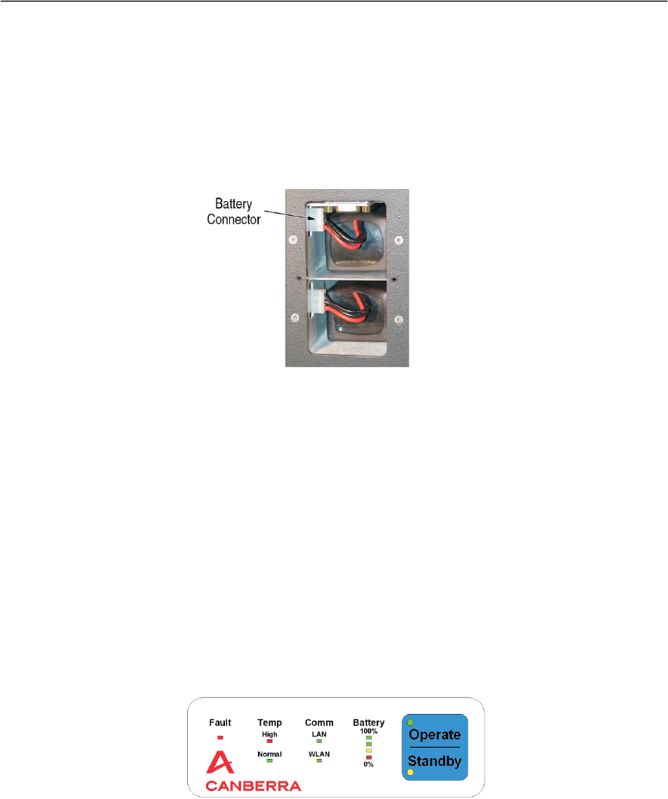
2. Remove the battery panel, which is on the back of the FALCON™ near the top; it is a
black panel with four thumb screws. The FALCON™ should look as shown in Figure
6.3.
Figure 6.3: FALCON 5000™ Battery ports and connectors
3. Inspect the two batteries for any bulging, cracking, or leaking. Dispose and replace
damaged batteries appropriately.
4. Install the two batteries, one in each slot by sliding the battery into its slot and
plugging in the white clips. Replace the foam behind the batteries so that they do not
slide around.
5. Replace the cover and hand tighten the screws (do not use a screw driver).
6. Attach the LAN cable from the FALCON™ to the computer.
7. If desired, attach a mouse, keyboard, and printer to the computer.
8. Turn on the FALCON™ by pressing the black button on the back panel of the
FALCON™, near the base.
9. The FALCON™ takes about 4 hours to cool depending on the ambient temperature.
The batteries last less than 3 hours. A “hot swap” is required to complete the cool
down.
10. On the top of the detector near the front is a white panel. See Figure 6.4 below:
Figure 6.4: FALCON 5000™ Control/Display Panel
11. Watch the battery power level indicator. If the yellow light goes out and the red light
comes on, this indicates that the power level in the batteries is less than 25%. Remove
the battery cover.

August 2019 Section 6: Gamma Spectroscopy Procedures
FRMAC Fly Away Laboratory Manual 6-7
12. To perform a hot swap of the batteries, change out the batteries one at a time. If you
remove both batteries, the detector quickly heats back up, and you will have to
reinitiate the cooling process.
13. Replace the battery panel and hand tighten the screws.
14. When the FALCON™ is not ready for use, a red light appears under the Temp High
label. When this light is on, the high voltage is locked out and the FALCON™ is
unable to operate. When the temperature has fallen to an acceptable range, the red light
goes out and a green light under the label Temp Normal lights up.
15. On the same panel as in the previous step, there is a large blue button
STANDBY/OPERATE. When turning the FALCON™ on, a yellow light is on next to the
label STANDBY. When the green temperature light is lit, hold the blue
STANDBY/OPERATE button for about 3 seconds, until the green light next to OPERATE
turns on.
16. The green light under COMM LAN should be on; if not, check the cable on both ends
and make sure the tablet computer is on.
6.5.2 Initializing the High Voltage
1. At this point, the FALCON™ should be setup and cooled down to the operating
temperature. The green light next to the “Operate” label should be lit. If not, repeat the
above steps.
2. Open the folder “Genie 2000” on the Windows desktop.
3. Inside the Genie 2000 folder, double click on the “Gamma Acquisition and Analysis”
file.
4. Open the detector by going to FILE, and then select OPEN DATA SOURCE. This opens
a new window.
5. Near the center of the window are two radio buttons: file and detector. Click the
detector radio button. This will populate a list of detectors that have been installed on
this computer.
6. Select the appropriate detector (i.e., FAL03 or FAL05) and then click OPEN. If you
receive an error indicating that the required hardware is unavailable, a system reboot
of the computer and/or the detector may be necessary. Completely cycling the power
to the FALCON (pressing the button on the back of the unit, waiting 3-5 seconds and
pressing it on again) usually resolves this issue. If the problem persists, consult the
troubleshooting guide.
7. Near the top left of the screen, select MCA and then click ADJUST. This will open a
new window near the bottom of the screen.
8. Near the top of the new screen are several radio buttons. Select the HVPS (High
Voltage Power Supply) tab.
9. In the middle left of the window are two buttons under STATUS. Select the ON radio
button. In the top left of this window, a sign that says “Wait” appears. If the detector is
not defined on the system refer to the manufacturer’s detector sheet for the appropriate
voltage to apply.
10. Wait until this sign goes away; it will take between 10 and 30 seconds.
11. Place the QC source on the detector; refer to Section 6.5.3, Quality Control (QC)
Check, for instructions on how to place the source.

August 2019 Section 6: Gamma Spectroscopy Procedures
FRMAC Fly Away Laboratory Manual 6-8
12. To the left of the black screen in the Genie 2000 window are several buttons: START,
STOP, EXPAND and CLEAR. Press the START button.
13. The FALCON™ begins to acquire and display the spectrum on the screen. If desired,
click the EXPAND button, which opens a new screen above the main screen that
displays a zoomed-in portion of the spectrum. You can adjust the expanded view by
moving the white box that has appeared in the primary screen to move the zoomed
section left and right, and you can zoom in and out with the up and down arrow keys.
14. Ensure that the following is true:
o 1274.53 keV peak is approximately in channel 3480.
o 86.54 keV peak is approximately in channel 237.
15. If the peaks need adjusting, press STOP and then press CLEAR and wait about a minute
and try again by pressing START. If after 3 attempts the peaks do not appear where
they should, a gain adjustment may be needed. To adjust the gain navigate to MCA
and then click ADJUST. Click the GAIN radio button and adjust the gain until the peaks
fall in the correct channels. Seek guidance from the FAL Manager of assistance.
16. If the peaks are in their anticipated locations, close this window by clicking the X in
the top right of the screen. When a pop-up appears asking if you want to save your
changes, select NO.
17. Continue to Section 6.5.3, Quality Control (QC) Check.
6.5.3 Quality Control (QC) Check
A quality control check must be run at the beginning of a shift and at the end of a batch of
samples. If the case occurs that a batch spans a shift, the QC check must be run at the beginning
of the shift. A batch of samples comprises of up to 20 samples, including the quality control
check and background check.
1. Place the quality control source in the correct position, typically centered on the face
of the collimator or cover.
2. Launch the γ-RATS script if it is not already running.
3. Select the detector in the INPUT combo box if it is not already selected.
4. Select the DAILY QUALITY radio button in the COUNT TYPE section. The library,
geometry, background, count time, quantity, sample date and sample time should load
with the appropriate information. Do not change these parameters unless instructed to
do so by the FAL manager.
5. Enter your analyst initials in the ANALYST text box.
6. In the SAMPLE NUMBER text box enter Q[YY][MM][DD][N], where the bracketed
values are replaced with:
1. [YY] – 2-digit year
2. [MM] – 2-digit month
3. [DD] – 2-digit day
4. [N] – 1-digit indicating the number QC checks run that day
7. Press the COUNT button.
8. Next, the script procedure automatically clears the MCA, acquires a spectrum, and
analyzes and performs a peak centroid, efficiency, and FWHM check. The QA values
automatically update the specified Quality Assurance File (QAF). The quality

August 2019 Section 6: Gamma Spectroscopy Procedures
FRMAC Fly Away Laboratory Manual 6-9
assurance report is then sent to the Genie2K report review screen below the spectrum
view in a newly opened data source with the name that matches the sample number:
a. Review the spectrum to ensure that the expected peaks are present.
b. If no parameters are flagged on the report, the system is ready for use.
c. If any of the parameters of the quality assurance report fall outside the control
limits, another quality assurance measurement should be performed.
d. If the second count returns any parameter that falls outside the control limit, tag
the detector as out of service and investigate the problem. Record the instrument
as out of service in the instrument logbook. Consult the FAL manager to
determine the next appropriate action.
NOTE: If the error message “Detector not available” appears at this point, check to make sure
that the detector is not open in another application window. Also, make sure that the detector is
in the “operate” mode and the green LED light is on. If this still does not fix the problem,
perform the following steps:
a. Close the QC program.
b. Place the detector in standby mode.
c. Reset the VDM (Virtual Data Manager).
d. Place the detector in the “Operate” mode.
e. Restart the HVPS.
f. Restart the QC program.
Finally, if these steps do not work, power cycle the instrument by pressing the power button on
the back panel, waiting 3-5 seconds, and then pressing it again to power the instrument back on.
NOTE: Should the error “Too few points to perform test” appears, simply click OK and rerun
the QC measurement until there are enough points.
6.5.4 Performing a Background
During a response, radiological conditions (i.e., background) could change drastically from time
to time. It is very important to have a spectrum that characterizes the environmental background
when performing gamma spectroscopy. The Background measured in this section is used for
subtracting the ambient radiation and is verified by periodic blank measurements, See 6.5.7
Performing a Background Check (Blank). This requires measuring the background and entering
the results into a Quality Assurance File that the blank measurements can check against.
NOTE: This section shall be performed as part of the deployment setup of the Falcon.
NOTE: If the blank falls outside the prescribed limits, it is very important to take a new
background measurement. This includes geometries that require the collimator to be removed. In
such cases if the sample provides shielding count a blank sample matrix in the same geometry.
Perform this section for all geometries that deviate enough that the blank falls outside the
prescribed limits.
1. Launch the γ-RATS script if it is not already running.
2. Select the detector in the INPUT combo box if it is not already selected.

August 2019 Section 6: Gamma Spectroscopy Procedures
FRMAC Fly Away Laboratory Manual 6-10
3. Select the BACKGROUND radio button in the COUNT TYPE section. The library,
geometry, background, count time, quantity, sample date and sample time should load
with the appropriate information.
4. Enter your analyst initials in the ANALYST text box.
5. In the SAMPLE NUMBER text box enter B[YY][MM][DD][N], where the bracketed
values are replaced with:
a. [YY] – 2-digit year
b. [MM] – 2-digit month
c. [DD] – 2-digit day
d. [N] – 1-digit indicating the number QC checks run that day
6. Press the COUNT button.
7. Make a note of the filename, sample number, and count conditions present during the
background so the spectrum can be reused if necessary.
8. Wait for the count to finish.
9. When the analysis is complete, the file is saved with name in the format
[NN]_FAL_[YY][MM][DD] where the bracketed values are replaced with:
a. [YY] – 2-digit year
b. [MM] – 2-digit month
c. [DD] – 2-digit day
d. [NN] – 2-digit number of the Falcon.
During a routine analysis, you can choose this background to be subtracted from a
sample spectrum or select LATEST to use the latest. A report will print displaying the
total counts in three regions.
10. Open the Bkg.QAF file for the background in the Quality Assurance Editor
(C:\Genie2k\EXEFILES\qa.exe).
11. Select Edit-defs → Parameter Definitions… and press MORE…
12. Under the User Driven Tests (cps) enter the results from the background count found
on the report for the corresponding parameter in the MEAN text box.
13. Enter 10% of the Mean in the Std Dev text box.
14. Move to the next parameter by clicking in NEXT button.
15. Repeat steps 12-14 for all the parameters.
16. When finished, click OK to close the Full Parameter Edit window, and OK to Close
the Parameter Definition Edit window.
17. Select File → Save, then close the Quality Assurance Editor.
18. Record the background in the instrument logbook and take note of any non-routine or
special reasons why the background was collected.
6.5.5 Gamma Library Creation
The automatic electronic data deliverable (EDD) generator for the FALCON™ will force a
Region of Interest (ROI) and calculate an activity for every nuclide in the library independent of
whether the nuclide was detected or not. To avoid reporting undetected nuclides, a gamma
library should be created upon arrival that contains only the nuclides of interest for that event and
any others that happen to be detected on the sample.

August 2019 Section 6: Gamma Spectroscopy Procedures
FRMAC Fly Away Laboratory Manual 6-11
1. Determine the nuclides of interest by finding the requested nuclides on the Analysis
Request Form. It may be necessary to add nuclides as they appear in the spectra of
specific samples.
2. If necessary, open the “Genie 2000” program group by double clicking the icon.
3. Double click on the icon titled NUCLIDE LIBRARY EDITOR.
4. In the top section of the Nuclide Library Editor, enter the information into the fields
for the Nuclide Name (e.g. Co-60), Half-Life, and Uncertainty. Be sure the appropriate
radio button is selected for half-life units. Press the Add Nuclide button at the bottom
of the window and the information entered will appear in the lower section.
5. In the center section, enter the information into the Energy, Abundance, and
Uncertainty (left field is for energy uncertainty and the right field is for abundance
uncertainty) fields. Uncertainty is entered at 1-sigma. If the energy line is the most
abundant and does not interfere with any other nuclide lines, select the Key Line check
box. Press the Add Line button and the line will appear below the nuclide specified in
the top section.
6. If the nuclide has more gamma lines, overwrite the information in the center section
and press the Add Line button.
NOTE: Only one nuclide line can be the key line for a nuclide; this will appear as an asterisk in
front of the energy. The software will honor the last line added with the Key Line check box
checked.
NOTE: It may be easier to pare down an existing library than to create a new one. To do so,
open a large existing library and save as a new name. Begin removing nuclides by selecting them
in the lower section and pressing the Delete button. Save the file and close the Nuclide Library
Editor.
7. Check all the entries against a reputable source for accuracy and correctness. Due to
the tedious nature of library creation and the need for high accuracy, have another
FAL member check the entries.
8. Select SAVE AS command from the Nuclide Library Editor. In the FILE NAME field,
enter a meaningful name (e.g. the event name) for the library with the extension NLB.
In the DESCRIPTION field enter a meaningful description.
9. Click on the OK button to save the Library file. The Library file is saved in the
directory C:\genie2K\camfiles with the name given in Step 8 and the extension NLB.
It will now be available for use in Gamma RATS in the library drop-down menu.
6.5.6 Sample Analysis
1. Place the sample in the appropriate geometry that matches the calibrations or iSOCS
model on the machine.
2. Launch the γ-RATS script if it is not already running.
3. Select the detector in the INPUT combo box if it is not already selected.
4. Select the SAMPLE radio button in the COUNT TYPE section.
NOTE: The CUSTOM ASF can also be selected for an analysis that differs from the standard
analysis. Enter the sample type (CAM Parameter: STYPE) in the box and browse for the
Analysis Sequence File (ASF) to be used.

August 2019 Section 6: Gamma Spectroscopy Procedures
FRMAC Fly Away Laboratory Manual 6-12
5. Select Library (e.g., FRMAC.nlb).
6. Select a geometry (e.g., AF0AT3F). If no calibrated geometry is available, refer to
Appendix A of this manual to create an efficiency calibration using iSOCS™. Note
that a sample can be counted with a “dummy” calibration file and reanalyzed with the
proper mathematical efficiency model later. Table 6.1 describes commonly
encountered calibrations that are performed on the FALCON™.
7. Select the geometry accuracy radio button underneath the Geometries.
a. Select Regular if the sample exactly matches the calibrated geometry in matrix,
location, and size.
b. Select Similar if the sample is like the calibrated geometry in matrix, location, or
size. Note that this selection will apply a caveat to the analytical report stating
that the counting geometry was imprecise and could lead to biases in the results.
This option is to only be used when the deviation from the calibrated geometry is
minor. For example, if the calibrated geometry is one gallon of water in a
Cubitaner counted against the collimator face, but the sample is 0.95 gallons of
water in the same container and counted in the same location, the Similar option
should be used.
c. Select Irregular if the sample was not counted in a configuration that was
calibrated for or if the sample was not close to the calibration standard. This will
lead to a caveat on the report that states that the results are to be used as
identification only. Quantification is impossible when the sample was counted in
a configuration that was not calibrated for or modeled.
17.
Table 6.1 shows the common calibrations performed on the FALCON™ system.
Table 6.1: Calibration Descriptions
Calibration Name
Description
#AF2.CAL
2-inch glass fiber air filter on contact with collimator
cover
#CUB.CAL
1-Liter Cubitainer filled with water counted on the
collimator cover
#SGLD.CAL
Gladware container with approximately 500 grams of
soil counted on contact with the collimator cover with
the larger surface facing the detector. Typically used for
ground deposition samples.
#AFCC.CAL
2-inch face loaded charcoal cartridge counted with the
inlet side on contact with the collimator cover.
Suffix
Description
AT1FT
Sample was counted exactly 1 foot and on axis with the
detector collimator face. Typically used for samples that
cause dead time to exceed 10% when on contact.
AT3FT
Sample was counted exactly 3 feet and on axis with the
detector collimator face. Typically used for samples that
cause dead time to exceed 10% when at 1 ft.

August 2019 Section 6: Gamma Spectroscopy Procedures
FRMAC Fly Away Laboratory Manual 6-13
NOTE: # denotes the detector number that the calibration applies to.
8. Background Subtraction:
a. Uncheck the box if a background has not yet been run. If one has not been run
yet, the background can be subtracted later in a reanalysis of the spectrum.
b. If a background has been run and analyzed, place a check in the SUBTRACT BKG
box.
c. Choose the background count that most closely characterizes the environmental
radiation levels at the time of sample acquisition. “Latest” will find the last run
background. Check the instrument logbook for information regarding the
backgrounds. If there is any doubt as to what background to use, or if a new
background should be run, consult the FAL manager.
NOTE: In most portable count situations, the acquisition time for the background should be set
to the same acquisition time or longer as the sample for which the background analyses will be
applied. However, the software will make time corrections if the count times differ.
NOTE: In practice, the environmental background is taken prior to sample analysis. While this
is possible in most situations, samples may need to be counted prior to the determination of
background. This is acceptable if it can be shown that the environmental levels of radiation had
not changed between the sample measurement and the background measurement. The sample
spectrum must be reanalyzed with the most applicable background. If the detector is moved, a
new background must be taken. Record any detector movements or changes in the radiological
environment in the instrument logbook.
9. Enter count time for the analysis in seconds. The minimum count time is determined
by the FAL manager. This is done using the required critical level which is indicated
on the ARF. Or the required count time indicated on the ARF.
10. Enter your analyst initials in the ANALYST text box.
11. In the SAMPLE NUMBER text box enter the SCF identification number (e.g., SCF-
0001).
12. Enter the sample quantity and select the appropriate units. Ensure that the selected unit
matches the units from the requested critical level.
13. Enter or select the Sample Date (i.e., the date to which the nuclides will be decay
corrected) and the sample time in a 24-hour format (hh:mm).
14. Once data acquisition is complete, the spectrum is analyzed, and a detailed report is
generated along with an electronic comma separated variable (csv) file.
15. Carefully review the analysis report for mistakes or problems with the data. Sign and
date the “Analyzed by” line on the report.
16. Have the report reviewed a second time by another FAL staff that is trained in gamma
spectroscopy.
17. Import the .csv file into excel and enter the remaining information. The information is
outlined in Table 6.2
Table 6.2: Routine Analysis Required Sample Information
FALCON™ Sample Input Parameters

August 2019 Section 6: Gamma Spectroscopy Procedures
FRMAC Fly Away Laboratory Manual 6-14
Analysis Request #
This must match the tracking number on the analysis request form (e.g. ARF-
00002)
QC Batch ID
ARF numbering appended with a letter (e.g. ARF-0005-A)
Sample Matrix
Pull Down (Air Filter, Feed, Food, Instrument, Milk, Moving Air Filter,
Moving Instrument, Other, Soil Swipe, Vegetation, Water) – match what is
written on the ARF
Moisture Property
*only applies to soils. If the soil was dried in a laboratory and the mass
entered was the dry mass, select dry. If the sample was not dried and the wet
mass was used as the aliquot, select wet. For matrices other than soil, or if no
soil mass was used as the aliquot, select N/A.
18.
Samples that are analyzed by the FAL gamma spectrometer can be reanalyzed with different
efficiency files, libraries, backgrounds, etc. at any time.
18. Launch the γ-RATS script if it is not already running.
19. Select “file” in the INPUT combo box if it is not already selected.
20. Browse for the file by pressing the … button next to Sample number. This will load
the information into the form.
21. Make the desired changes and Press RE-ANALYZE.
NOTE: Checking the “Use Stored ASF” box will use the Analysis Sequence File (ASF) stored in
the CAM File and not the ASF associated with the sample type.
6.5.7 Performing a Background Check (Blank)
Background check ensures the environmental background still represents the ambient
background and can be used for background subtraction. A background check must be measured
to confirm the background once per quality control batch.
1. Remove all sources of radiation away from the detector.
2. Launch the γ-RATS script if it is not already running.
3. Select the detector in the INPUT combo box if it is not already selected.
4. Select the BLANK radio button in the COUNT TYPE section. The library, geometry,
background, count time, quantity, sample date and sample time should load with the
appropriate information.
5. Enter your analyst initials in the ANALYST text box.
6. In the SAMPLE NUMBER text box enter C[YY][MM][DD][N], where the bracketed
values are replaced with:
• [YY] – 2-digit year
• [MM] – 2-digit month
• [DD] – 2-digit day
• [N] – 1-digit indicating the number QC checks run that day
7. Press the COUNT button.
9. Next, the script procedure automatically clears the MCA, acquires a spectrum, and
analyzes and performs a peak centroid, efficiency, and FWHM check. The blank
values automatically update the specified Quality Assurance File (QAF). The quality
assurance report is then sent to the Genie2K report review screen below the spectrum
view in a new data source matching the configured file name for blanks:

August 2019 Section 6: Gamma Spectroscopy Procedures
FRMAC Fly Away Laboratory Manual 6-15
g. Review the spectrum to ensure that there no unexpected peaks present.
h. If no parameters are flagged on the report, the system is ready for use.
i. If any of the parameters of the quality assurance report outside the control limits,
another blank measurement should be performed.
j. If the second count returns any parameter outside the investigation limit, a new
environmental background must be run. Consult 6.5.4 Performing a Background.
6.5.3 ISOCS Check
An ISOCS control check must be run quarterly. Place the ISOCS check source control source in
the correct position, typically in the jig with the collimator removed.
1. Launch the γ-RATS script if it is not already running.
2. Select the detector in the INPUT combo box if it is not already selected.
3. Select the ISOCS CHECK radio button in the COUNT TYPE section. The library,
geometry, background, count time, quantity, sample date and sample time should load
with the appropriate information. Do not change these parameters unless instructed to
do so by the FAL manager.
4. Enter your analyst initials in the ANALYST text box.
5. In the SAMPLE NUMBER text box enter I[YY][MM][DD][N], where the bracketed
values are replaced with:
1. [YY] – 2-digit year
2. [MM] – 2-digit month
3. [DD] – 2-digit day
4. [N] – 1-digit indicating the number QC checks run that day
6. Press the COUNT button.
7. Next, the script procedure automatically clears the MCA, acquires a spectrum, and
analyzes and performs a peak centroid, efficiency, and FWHM check. The QA values
automatically update the specified Quality Assurance File (QAF). The quality
assurance report is then sent to the Genie2K report review screen below the spectrum
view in a newly opened data source with the name that matches the sample number:
e. Review the spectrum to ensure that the expected peaks are present.
f. If no parameters are flagged on the report, the system is ready for use.
g. If any of the parameters of the quality assurance report fall outside the control
limits, another quality assurance measurement should be performed.
h. If the second count returns any parameter that falls outside the control limit, tag
the detector as out of service and investigate the problem. Record the instrument
as out of service in the instrument logbook. Consult the FAL manager to
determine the next appropriate action.
NOTE: If the error message “Detector not available” appears at this point, check to make sure
that the detector is not open in another application window. Also, make sure that the detector is
in the “operate” mode and the green LED light is on. If this still does not fix the problem,
perform the following steps:
k. Close the QC program.
l. Place the detector in standby mode.

August 2019 Section 6: Gamma Spectroscopy Procedures
FRMAC Fly Away Laboratory Manual 6-16
m. Reset the VDM (Virtual Data Manager).
n. Place the detector in the “Operate” mode.
o. Restart the HVPS.
p. Restart the QC program.
Finally, if these steps do not work, power cycle the instrument by pressing the power button on
the back panel, waiting 3-5 seconds, and then pressing it again to power the instrument back on.
NOTE: Should the error “Too few points to perform test” appears, simply click OK and rerun
the QC measurement until there are enough points.
6.6 Non-Routine Operations
6.6.1 Calibration
6.6.1.1 Certificate Creation
Certificate creation can be performed by several methods in Genie™. The following presents the
recommended method. It is acceptable for an experienced user of Genie™ to use short-cuts.
Genie™ references a user selected certificate as a reference point to determine the energy
dependent efficiencies.
1. With the assistance of the FAL Manager, select an appropriate NIST Traceable source
for a calibration. Each source comes with a certificate declaring the radionuclides in
the source, their activity, and reference date.
2. If necessary, open the “Genie 2000” program group by double clicking the icon.
3. Double click on the icon titled CERTIFICATE FILE EDITOR.
4. At the top third of the Certificate File Editor screen are entry fields for Title, Quantity,
and Assay Date. Edit the Title information to include source manufacturer, source
geometry, and manufacturer’s source number. Enter “1” in the sample Quantity field.
Edit the Assay Date to reflect the date and time of source fabrication.
NOTE: The Assay Date is used for decay correction during efficiency calibrations. Enter
the Assay Date in the format mm-dd-yy hh:mm:ss AM or PM. (Example: 03-01-99
12:00:00 PM.)
5. In the center of the screen are the fields Nuclide, Half-Life, Energy, Half-Life
Uncertainty, Emission Rate and Emission Rate Uncertainty. Be sure the appropriate
radio button is selected for the Half-Life units. Uncertainty is entered at 1-sigma,
some conversion from the certificate value may be necessary.
NOTE: You are allowed only one line per nuclide. If more than one line is being used for
the calibration, you need to enter the nuclide twice, such as 1173 KeV and 1332 KeV for
Co-60.
6. Check all entries against the original source certificate for accuracy and correctness.
Due to the tedious nature of certificate creation and the need for high accuracy, also
have another FAL member check the entries.

August 2019 Section 6: Gamma Spectroscopy Procedures
FRMAC Fly Away Laboratory Manual 6-17
7. Select the SAVE AS command from the Certificate File Editor File menu. In the FILE
NAME field, enter the manufacturer source number with the extension CTF. In the
DESCRIPTION field, enter the source geometry.
8. Click on the OK button to save the certificate file. The certificate file is saved in
directory C:\genie2k\camfiles with the manufacturer source number for file name and
with the extension “CTF.”
6.6.1.2 Initial Energy Calibration
An initial energy calibration is recommended ONLY when setting up a new instrument or after
receiving an instrument from the manufacturer following any repairs. The point of the initial
energy calibration is to align the peaks to their correct channel based on 3000keV at channel
8192.
1. The following points are suggested values to use for a standard 30 – 3000 keV range:
Table 6.3: Suggested Calibration Values
Nuclide
Energy(keV)
Channel
Am241
59.9
163
Cs137
661.2
1809
Co60
1173.2
3203
Co60
1332.5
3638
2. To determine the correct channel for the source being used or desired energies, a
simple ratio can be applied by dividing the 8192 ch/3000 keV.
3. Take each energy peak in keV and multiply by the ratio. Round to the nearest whole
number to obtain the channel. Note these channels and energies for later use.
4. Open the gamma acquisition and analysis window.
5. From the File menu select OPEN DATASOURCE…
6. Select the Falcon unit.
7. If any spectrum counts are present, clear the spectrum.
8. Begin a count ensuing that as close to 10,000 counts are collected in several peaks
across the energy spectrum.
9. From the Calibrate menu, select ENERGY ONLY CALIBRATION…
10. Enter the energy and channel, and then click ACCEPT for each peak.
11. Delete the peaks if necessary by selecting the peak and click DELETE.
12. After entering all peaks, click the SHOW… button.

August 2019 Section 6: Gamma Spectroscopy Procedures
FRMAC Fly Away Laboratory Manual 6-18
Figure 6.6: Energy Calibration Curves Window Showing Peaks
13. The peaks are represented as green squares. They should all line up on the blue line.
14. Select SHAPE to view the shape curve. This curve should be hyperbolic (square root
(y=√x) shape).
19.
Figure 6.7: Energy Calibration Curves Window Showing the Shape Curve
15. Each square should line on the curve or close to it.
16. After verifying the points, click OK to exit out of the curves.
17. When complete, click OK to complete the energy calibration.
18. Place a source on the detector face. The following steps assume that an Am-241, Cs-
137, and Co-60 source is being used. Make the necessary adjustments for different
sources.
19. Adjust the present time to at least 1000 seconds. If the deadtime of the detector is
>50% you will need to move the source further away from the detector.
20. Click on MCA menu.
21. Select ACQUIRE SETUP.
22. Ensure that seconds is selected.

August 2019 Section 6: Gamma Spectroscopy Procedures
FRMAC Fly Away Laboratory Manual 6-19
23. Enter 1000.
24. Select OK to exit.
25. Click START under Acquire to being counting.
26. Adjust the ADC zero, amplifier gain, and fine gain until the 59.5 keV line from Am-
241 and 1332.5 keV line from Co-60 are approximately at the desired channels
(Example: Channel 162 and Channel 3639, respectively, for a 3000 keV/8192 channel
relationship).
NOTE: Use the Clear button to erase spectral data after adjustment of the amplifier gain
and fine gain.
27. Adjust the ADC Lower Level Discriminator (LLD) setting so that the channels
representing the first 35 keV are clear.
28. When adjustments have been made, stop the count by clicking STOP.
29. Exit out the gamma acquisition and analysis window. When prompted by the software,
select that you wish to save the changes.
30. Record this calibration in the instrument logbook and proceed to Section 6.6.1.3,
Energy and Shape (FWHM) Calibration.
6.6.1.3 Energy and Shape (FWHM) Calibration
The following steps should use National Institute of Standards in Technology (NIST) radioactive
sources that are not available in the FAL load out. This procedure can be performed in the field
with any source of known energies if necessary. When performing the calibration, the deadtime
of the detector should be kept below 50%. To decrease the deadtime you will need to move the
source further away from the detector.
1. Open the detector in Genie2K.
20.
NOTE: If this is the first energy calibration after the initial calibration a prompt may appear that
mentions a questionable calibration. Select “yes” and continue the procedure.
2. Place the source on the collimator face.
3. Clear the existing spectrum (if any) by pressing the CLEAR button. Set the preset by
navigating to MCA → Acquire Setup… and enter a preset time that ensures that most
of the source peaks have an area of at least 10,000 counts.
4. Click START under Acquire to being counting.
3. Once the spectrum has been acquired perform a Peak Locate and Peak Area analysis
by navigating to Analysis → 1 Execute Sequence → FAL Peaks. This should generate
a peak search report and send it to the printer as well as generate region of interests
(ROIs) around the prominent peaks.
4. Navigate to Calibrate → Energy Full → By Certificate File… and select the desired
certificate (e.g. ENERGY.CTF). This file should contain all the relevant peaks for
radionuclides present in the source that was used.
5. Move the ROI index to the peak that corresponds to the highlighted energy from the
certificate using the + and – Buttons. Once the ROI index aligns with the highlighted
line press the CURSOR button. The Channel, FWHM and Low Tail should calculate.

August 2019 Section 6: Gamma Spectroscopy Procedures
FRMAC Fly Away Laboratory Manual 6-20
NOTE: If the Low tail remains at zero low tail is not activated. To activate the low tail: navigate
to Calibrate → Setup… and check the Low radio button under the Tail Curves section.
6. Repeat Step 5 until all peaks have values for Channel, FWHM and Low Tail.
7. View the Calibration curve by pressing SHOW…
8. It is recommended to not remove outliers that are at the lowest and highest end of the
energy spectrum. These are needed to bound the calibration. If they appear to be
undesirable, consult with the FAL Manager. Once outliers are moved they cannot be
retrieved. To remove outliers:
a. Count the green data points from the left to the right.
b. Enter the number of the peak you wish to drop in the small dialog box labeled
“Peak:”
c. Click DROP PK to drop the peak from the calibration.
d. Repeat this process for all outliers.
9. When complete and if a printer is available, click on the PRINT button to obtain a hard
copy of the energy and shape calibration curves. Click on the available radio button to
toggle between energy and shape curves.
10. Click on the OK button to terminate the “Energy Calibration Curve” screen.
11. Navigate to Calibrate → Store…
12. Save the spectrum as C:\genie2k\calfiles\E#YYMMDD.cal, where # is the detector
number and YYMMDD is the year, month, and day the calibration is performed.
13. Print the energy calibration reports by navigating to Analyze → L Reporting → 1
Standard…
a. Select the CALIB.tpl for the template name
b. Select ECAL for the section
c. Change error Multiplier to 2.0
d. Check PRINTER in the Output to Section
e. Press EXECUTE.
14. Click the save icon to save the information to the MCA buffer. Close the data source,
Click “no” when prompted to save changes. The file has already been saved.
15. Obtain a copy of the Portable Gamma Spectroscopy Calibration checklist and approval
form from in Appendix B.
16. Fill out the form and attach the supporting documents on the checklist. Retain this
paperwork for filing with the efficiency calibration packages.
17. Record this calibration in the instrument logbook.
6.6.1.4 Efficiency Calibration
1. Run the daily quality control check prior to performing the efficiency calibration to
ensure that the detector is functioning properly.
NOTE: If this is the first calibration for the detector or a calibration after major repairs the
Quality Control Check can be bypassed.
2. Make sure a background has been taken in the same orientation that the detector is in
to ensure that there will be no interfering lines with the calibration.

August 2019 Section 6: Gamma Spectroscopy Procedures
FRMAC Fly Away Laboratory Manual 6-21
3. Obtain a mixed-nuclide standard in the geometry of interest. Do not use the source
used for quality control checks. If necessary, create a certificate file as described in the
Section 6.6.1.1, Certificate Creation.
4. Open the detector in Genie2K.
5. Place the source in the correct geometry.
6. Clear the existing spectrum if any by press the CLEAR button. Set the preset by
navigating to MCA → Acquire Setup… and enter a preset that ensure that most of the
source peaks have an area of at least 10,000 counts.
NOTE: the following steps are for calibrating with cascade summing corrections on, if cascade
summing is not to be used in analysis Navigate to Analysis → 1 Execute Sequence → FAL
Peaks and skip to step 9 then skip step 11. It is recommended that cascade summing corrections
are always used.
7. Click START under Acquire to being counting.
8. Once the spectrum has been acquired, perform a Peak Locate and Peak Area analysis
by navigating to Analysis → 1 Execute Sequence → FAL Calibration Peaks. Select
any calibration file (it does not matter which as it will be overwritten) and press LOAD.
9. Select the corresponding ISOCS geometry and press SELECT. This will process the
spectrum and generate a report.
10. Navigate to Calibrate → Efficiency → By Certificate File… and select the desired
certificate (e.g. Cubitaner.CTF).
11. Press the AUTO button to fill out the Efficiency and Error for each peak.
12. Check Perform Cascade Correction.
a. The Geometry Composer File should auto fill. If it does not, press Select and
browse to the corresponding ISOCS geometry file. The geometry file must be on
the instrument computer in the following folder:
C:\GENIE2K\isocs\data\GEOMETRY and have been actually run on the
computer (not just transferred from another computer) to work correctly.
b. Check Use ISOCS/LabSOCS Total Efficiencies and Detector Characterized for
LabSOCS.
c. Press AUTO and note the peaks that are corrected for cascade summing are
marked with an asterisk.
13. If using a dual calibration fit model, select the peak just below 100 keV and press
CROSS-OVER. An “X” will appear next to the error of the peak selected. It is best to
select the peak nearest the crest (maximum) of the calibration curve as the cross-over
peak.
14. Press Show… to review the calibration curve. Select the model that best fits the points
and adjust the order for the best fit. Make a note of the model chosen. If the dual
model is selected make sure the curves match well (i.e. first derivatives are roughly
equal). A good fit is characterized by one inflection point, smooth between the points,
and passes through or close to the points.
15. Close the Efficiency Calibration Curves window by pressing OK, then close the
Efficiency Calibration window by Pressing OK.
16. Navigate to calibrate → Store
a. Name the calibration file name as [detector number][geometry
name][YYMMDD] where values in the brackets are replaced by the detector

August 2019 Section 6: Gamma Spectroscopy Procedures
FRMAC Fly Away Laboratory Manual 6-22
number, the geometry name and the date in the format 2 digit year, 2 digit month
and 2 digit day, respectively.
b. It is helpful to fill out the EFF. GEOM ID with the geometry name.
c. Press STORE to finish.
17. Close the Geine2k window. Do not save by pressing NO.
18. Launch the γ-RATS script if it is not already running.
19. Expand the NON-ROUTINE section.
20. Select the model noted above, enter the geometry name and browse for the stored
calibration file.
21. Press SET CALIBRATION and the new geometry will appear in the geometry box.
22. Open the file just created (C:\GENIE2K\CALFILES\*.cal where * is the file name
configured in the gamma.ini file) in Genie2K and generate the calibration report.
a. Analyze → L Reporting → 1 Standard…
b. CALIB.TPL for the template, EffCal for the SECTION NAME, 2.0 for the ERROR
MULTIPLIER and output to PRINTER checked.
c. Press EXECUTE.
23. Print the Calibration graphs by navigating to Calibrate → Efficiency Show… and
pressing PRINT. Print both in Linear and Log scale, use the radio button in Scale
section to toggle between the two.
24. Count an identical source (preferably a different source than the one used for
calibration if possible) using the 6.5.6 Sample Analysis using the FALCON™. Verify
(at a minimum) that a low (<70 keV), mid (500-800 keV), and high (>1200 keV)
values match the certified values to within +/- 20%. Retain the analysis report and the
bias calculations for the calibration package.
25. Obtain a copy of Gamma Spectroscopy Efficiency Calibration checklist and approval
form from Appendix B.
26. Fill out the form and attach the supporting documents according to the checklist. Next,
sign the “Reviewed By” line and have the FAL Manager or designee approve the
form.
27. File the efficiency calibration package in accordance with FRMAC processes.
28. Record each calibration in the instrument logbook.
6.6.2 Initial Setup from Factory (New FALCON™ Unit)
This section describes how to connect and set up the FALCON™ 5000 portable gamma
spectrometers. The section should only be used if it is the initial setup of the detector or the
detector was sent back to the factory and everything needs to be reinstalled.
6.6.2.1 Required Equipment
• FALCON™ 5000 portable High Purity Germanium Detector with integrated MCA
• Laptop computer with Windows
• HyperTerminal program
• RS232(serial) cable
• Virtual RS232 port via USB if applicable
• Radioactive Source (mixed gamma) and holding jig issued by Canberra
• External DC Power Package

August 2019 Section 6: Gamma Spectroscopy Procedures
FRMAC Fly Away Laboratory Manual 6-23
• Lithium-ion batteries
• Tungsten Collimator
• Genie™ 2000 Software
6.6.2.2 PPE Requirement
None
6.6.2.3 Setup Procedure
1. Unpack the detector, the accompanying power supply, batteries (2 per unit), and
associated cables.
2. Inspect the FALCON™ unit for any defects, missing parts, and the protective detector
cap.
3. Inspect the power supply for any damage or frayed cords.
4. Inspect the batteries for damage, leakage, or corrosion.
5. If anything is damaged or out of place, contact the manufacturer’s service
representative to report any damage.
6. Assign a name to the detector (FAL##, where ## is a number).
7. Place a label with the assigned name on the detector.
8. Remove the battery compartment screws on the back of the FALCON™.
9. Install the batteries such that each battery slides easily into each battery compartment.
If there is any resistance in sliding the battery, remove the battery and re-adjust the
orientation of the batteries. The electrical connection of the battery should extend
toward the back of the FALCON™.
10. Connect the battery’s electrical connection to the left side of the unit located inside the
battery compartment. The release clip on the connector should point toward the front
of the unit.
11. The batteries are shipped with two rectangular pieces of foam, one per battery. Install
the foam on the right side of the electrical connection. As seen in Figure 6.8, the
battery wire should not contact the right side of the battery compartment.
21.

August 2019 Section 6: Gamma Spectroscopy Procedures
FRMAC Fly Away Laboratory Manual 6-24
INCORRECT CORRECT
Figure 6.8: Placement of Foam Spacers to Avoid Damage to Connector
12. Place the battery compartment cover back into place. Hand-tighten all four bolts. Do
not use a screwdriver.
13. Connect external power supply to the FALCON™ unit.
14. Remove protective end cap and screw on collimator.
15. Switch the power switch to the on position on the power supply.
16. Press and hold the power button on the FALCON™, until the power LED on top of
the unit is on.
17. Each unit requires up to 4 hours to reach normal operating temperature depending on
the initial conditions in the room.
18. When the cryostat reaches the desired temperature, the temperature light indicates
NORMAL. If after 6 hours the temperature light does not indicate normal, this may be a
failure of the cryostat mechanism. Report this to the FAL manager.
6.6.2.4 Establishing the Local Area Network (LAN)
Every FALCON™ (from the manufacturer) is set up with the wireless LAN enabled. If the unit
is purchased with a tablet computer, the computer also has the “WIFI” enabled. In both
instances, the “WIFI” needs to be disabled. While disabling the WIFI, the wired LAN has to be
enabled to allow communication with the computer.
NOTE: Performing the following steps to disable the WIFI requires a computer with a serial
port or a computer with a serial port adapter and a COM port communication software
(HyperTerminal is use described but others PowerShell, putty, etc. are acceptable).

August 2019 Section 6: Gamma Spectroscopy Procedures
FRMAC Fly Away Laboratory Manual 6-25
1. If a USB to Serial adaptor is being used the computer port must be setup prior to
connection. If a normal serial cable is being used, skip to step 8.
2. Connect the serial adapter to a USB port on the computer.
3. Right click on My Computer and select Manage.
4. Click on Device Manager.
5. Scroll down to Ports, right click, and select Scan for Hardware.
6. Insert the USB to Serial adapter driver CD and follow the prompt to install the driver.
7. Take note of the port name that the computer assigns the new hardware (i.e. COM4),
this will be the port that you must assign the HyperTerminal connection to.
8. If applicable, shutdown the FALCON™ unit by pressing and holding the off button on
the FALCON™ unit.
9. The top of the FALCON™ unit has a LED display that shows the status of the unit.
Remove the four hex socket heads that hold down the LED display.
CAUTION: Do not perform these steps while the unit is powered up. This may lead to
an electric shock or damage to the unit.
NOTE: Do not pull hard on the LED display cover as it is attached by wires.
10. Slightly lift the display cover. Inside is a ribbon cable with the RS232 female
connection. Pull out the cable, being careful not to pull the RS232 from the unit, but
enough to allow access to the port (Figure 6.9).
Figure 6.9: Access to the RS232 Port underneath the Display/Control Panel
11. Attach the RS232 cable to the FALCON™, and then attach it to the computer’s serial
cable.
12. Open the HyperTerminal program located in the Windows startup menu (All
Programs > Accessories > Communications).
13. The HyperTerminal program prompts for the new connection name. Enter
“FALCON.”
14. Select the communications port (it will mostly likely be COM1, but it may also be
whatever the program selects as the default COM port). Enter the following
communication properties:

August 2019 Section 6: Gamma Spectroscopy Procedures
FRMAC Fly Away Laboratory Manual 6-26
o Baud rate: 57600 bits per second
o Data bits: 8 data bits
o No Parity
o 2 stop bits
o No flow control.
15. Now that the HyperTerminal is setup, hold down the W key and at the same time
power up the FALCON™ via the push button. Hold both the W key and the power
button until all the lights are lit on the LED display cover. Release the power button
and then the W key.
16. Once the connection is established, not only with all the LEDs be lit, but the
HyperTerminal displays the following (Figure 6.10):
Figure 6.10: Example of the HyperTerminal
17. Press 0 SERVER.
18. Press 0 again to shift to “Wired only.”
19. If not already set, set the IP address of 192.0.0.###, where ### is the three-digit
detector ID number (e.g., FAL03 would have an IP address of 192.0.0.003).
20. Set the net mask as 255.255.255.0, and the default ‘No’ to change telnet config
password.
21. Press 9 to save and exit.
22. Power off the FALCON™ unit, and remove the serial cable from the computer and the
FALCON™ unit.
23. Tuck the FALCON™’s serial cable back into its case and screw down each hex head
bolt.
24. HyperTerminal may be closed out. Connect the LAN cable to the units LAN
connection, as well as to the computer. If the computer is already connected to a
network, a network switch or router needs to be obtained. If connecting to a switch or
router the I.P. address in the FALCON™ may need to be changed to conform to the
network gateway.

August 2019 Section 6: Gamma Spectroscopy Procedures
FRMAC Fly Away Laboratory Manual 6-27
NOTE: Contact the computer’s system administrator to setup the network connections if
the computer is having trouble communicating with the FALCON™.
6.6.2.5 Software Installation
1. Consult the FAL Manager or designee before installation to verify the correct versions
of all installation software (i.e., Genie™ 2000).
NOTE: There may be computers where CD-ROM installation is not available; it is
acceptable to install from a remote drive instead; consult the FAL Manager.
2. Insert the Genie™ 2000 Basic Spectroscopy CD in the CD-ROM in the computer.
3. Click on the Windows Start menu.
4. Select RUN.
5. Type in the drive letter followed by the colon symbol (e.g., d: ).
6. Click on SETUP.EXE. This loads the Genie™ 2000 menu.
Sentinel Driver Installation
NOTE: The Sentinel Drivers come with Genie™ 2000 starting with version 3.2.
1. Select Install/Update Sentinel Driver.
2. Follow the setup and accept the defaults.
3. For setup type, select COMPLETE.
Genie 2000 Basic Spectroscopy Installation
1. Select INSTALL GENIE™ 2000.
2. Select the default language.
3. Select INSTALL GENIE™ 2000 S504 INSPECTOR BASIC SPECTROSCOPY for the install
type.
4. Accept the terms of the license.
5. Installation prompts to verify installation to destination folder of c:\genie2k. Click
NEXT.
6. Install the Genie™ 2000 documentation and click NEXT.
7. Verify correct setup and click NEXT.
8. Select STANDARD install and click NEXT.
SNAP Driver Installation
1. Do not exit out of the CD-ROM. Open the following directory:
d:\Bin\G2KVx.x.x\XP_Vista, where x.x.x is the version number. Verify that the
aimsnap5.inf file is present.
2. The CD-ROM may be closed out.
3. Click on the Start Menu.
4. Go to My Network Places. If it is not located in the Start Menu, it is in the control
panel.
5. On the left side of the My Network Places screen, click on VIEW NETWORK
CONNECTIONS.
6. Right click on LOCAL AREA CONNECTION. Select any connection to edit.
7. Select PROPERTIES.

August 2019 Section 6: Gamma Spectroscopy Procedures
FRMAC Fly Away Laboratory Manual 6-28
8. Select INTERNET PROTOCOL (TCP/IP).
9. Click INSTALL.
10. Select PROTOCOL and then ADD.
11. Click on HAVE DISK.
12. Select BROWSE.
13. On the Locate File dialog box under Look in, find the CD-ROM drive.
14. Locate the aimsnap5.inf located on the CD-ROM under the directory above.
15. Select the aimsnap5.inf and then OPEN.
16. On the Install from disk dialog, click OK.
17. Click OK for the Canberra NDIS 5.0 SNAP Protocol Driver Vx.x, where x.x is the
version number of the SNAP driver.
18. Close out all the windows and restart the computer.
Gamma Analysis Software Installation
1. Remove the Basic Spectroscopy CD and insert the Gamma Analysis Software
2. Click on the Windows Start menu.
3. Select RUN.
4. Type in “d:” without the quotation marks if d: is the drive letter for the CD-ROM
drive.
5. Click on SETUP.EXE.
6. Select ENGLISH and then accept the licensing agreement.
7. The program loads a series of applications in the directory “c:\Documents and
Settings\All Users\Start Menu\Programs\Genie-2000.”
8. Press the DIRECTORY button (it looks like a folder with an arrow coming out of it).
9. Right click the Genie 2000 folder and copy.
10. Close out all windows.
11. On the desktop, right click and select paste. This action pastes a copy of the Genie
2000 folder.
12. Open the folder and verify that the icons for applications are in the Genie 2000 folder.
Interactive Peak Fit Software Installation
NOTE: Interactive Peak Fit Version 1.3.1 is the first version of software contained on a CD. All
previous versions are contained on a 3.5” floppy disk. If the version of Interactive Peak fit is on a
floppy disk, open the setup.exe from the a: drive.
1. Remove the Gamma Analysis Software CD and insert the Interactive Peak Fit CD.
2. Open the CD by the same method as the other two CDs.
3. Start the setup.exe file.
4. Select ENGLISH and accept the licensing agreement.
5. The Interactive Peak fit will install and then close out of all windows.
Quality Assurance Installation
NOTE: Insert the USB thumb drive to a port on the computer.
1. Open the disk in the same manner as the CDs except instead of a “d:” drive substitute
with the name of the USB drive. (i.e., “e:/”).
2. Click on the setup.exe file and select the defaults.

August 2019 Section 6: Gamma Spectroscopy Procedures
FRMAC Fly Away Laboratory Manual 6-29
3. The directory “c:\Documents and Settings\All Users\Start Menu\Programs\Genie-
2000” is displayed.
4. Right click on the Quality Assurance Editor and copy the icon.
5. Open the Genie2k folder on the desktop and paste the icon in the Genie2k folder.
6. Select ENGLISH and then accept the licensing agreement.
22.
Falcon5000 Software Installation
1. Insert the Falcon5000 (S513) Installation disc.
2. Open the disc and run the setup.exe file.
3. Follow the on-screen instructions and agree to all the defaults.
γ-RATS Software Installation
1. Locate the media with the FRMAC FAL files (also on the shire and CMWeb if
accessible).
2. Copy the Genie2K folder from the FAL files media the local C:\ drive and replace all
the files.
3. Navigate to the GENIE2K folder on the local C:\ drive and copu the γ RATS shortcut
to the desktop.
6.6.2.6 SETUP OF Multi-Channel Analyzer Input Definition (MID) File
The MID file describes the detector and its parameters.
1. Open the Genie2000 folder on the desktop.
2. Start the MCA Input Definition Editor. If you receive an “ICP node connect” error,
uninstall GENIE™ 2000 S504 INSPECTOR BASIC and Gamma Analysis, then reinstall.
3. On the menu bar, click on FILE.
4. Select NEW.
5. On the menu bar, click EDIT.
6. Select ADD MCA.
7. Under the Network MCA’s, select FALCON™ 5000 USING I2K-F5K.
8. Click on ADD.

August 2019 Section 6: Gamma Spectroscopy Procedures
FRMAC Fly Away Laboratory Manual 6-30
9. On the menu bar, click DEVICES. For the following parameters under device, select:
Table 6.4: FALCON 5000™ MCA Input Definition (MID) Settings Part 1
MCA
MCA Full Memory
8k
No of ADCs
1
Acq. Mode
PHA
IP Address
192.0.0.### (where ### is the 3-digit detector number. Ex.
FAL03 would have an IP Address of 192.0.0.003)
Stabilizer
Device Driver
I2K D-Stab
Control
Programmable
Internal
MCA
Power Management
Device Driver
I2K Power
Control
Programmable
Internal
MCA
DSP Gain
Device Driver
I2K Gain
Control
Programmable
Internal
MCA
DSP Filter
Device Driver
I2K Filter
Control
Programmable
Internal
MCA

August 2019 Section 6: Gamma Spectroscopy Procedures
FRMAC Fly Away Laboratory Manual 6-31
10. On the menu bar, click SETTINGS. For the following parameters under setting, select:
Table 6.5: FALCON 5000™ MCA Input Definition (MID) Settings Part 2
MCA
None
Stabilizer (defaults)
Gain Centroid
7680 ch
Gain window
8 chs
Gain Spacing
64chs
Gain ratio
1.000
Gain rate div
1
Correction rng
Ge
High Voltage
Range
Above the voltage if positive
Below the voltage if negative
Must encompass the voltage setting
Voltage Limit
Set slightly beyond the Voltage
Voltage
(established at factory)
Voltage setting is located on the falcon and
support box. Consult the detector manual to
obtain the operating voltage.
Inh signal
Positive
Power Management
Standby delay
100min
DSP Gain
Gain Attenuator
Off
FDisc Mode
Auto
LLD Mode
Manual
Fine Gain
1.4001x*
S-fine gain
0.99999%*
Course gain
X40*
FDisc Setting
1.0%
LLD
0.1%*
Inp. Polarity
Negative
Inh. Polarity
Positive
DSP Filter (default settings)
Rise Time
5.6
BLR mode
Auto
Preamp type
RC
Flat Top
0.8
FDisc shaping
Normal
Input
Input Name
FALNN (NN is the detector number, ie 03)
DetectorType
Gamma or X Ray – Ge
Input Size (Channels)
8192
* most likely to change during initial setup

August 2019 Section 6: Gamma Spectroscopy Procedures
FRMAC Fly Away Laboratory Manual 6-32
11. Save as FALNN, where NN is the detector number.
12. Load the database after closing the MID file or the editor.
13. Reopen the MCA Input Definition Editor if necessary.
14. Click on DATABASE.
15. Click on LOAD TO.
16. Select the newly created MID file and click LOAD.
17. Click DONE.
18. Close the MCA Input Editor.
6.6.2.7 Setup of the Quality Control QAF Files
The QAF file should only be setup if it is the initial setup of the detector or if the QAF file needs
to be recreated. The QAF stores quality data about each QC/BKG/ISX/LCS performed and the
QC parameters. A source should be chosen such that the dead time of the detector is less than
3%, and there are at least three gamma emissions in the low (<100 keV), Mid (100-1100 keV),
and High (>1100 keV). The library for the QAF will have to be changed to account for the
energy lines described below (Tables 6.6, 6.7, and 6.8). The recommended settings of the control
limits (UPPER and LOWER in the Parameter Editor) are:
• FWHM: ± 15% of the baseline,
• DCA: ± 15% of the baseline,
• CENTRD: ± ½ of the FWHM at the energy,
• Background: ± 10% of environmental background measurement,
• ISX/LCS: Between ± 25% of the certified value
where the baselines are determined by at least 5 QC Runs.
1. Open the Quality Assurance Editor.
23.
24. NOTE: If an error appears that reads “Add-Defs menu creation error: “2”, you must
reinstall the quality assurance editor.
25.
2. Select FILE on the menu bar select “new”.
3. For the peak centroid, navigate to ADD-DEFS →PEAK SEARCH → PEAK CENTROID.
Table 6.6: QC QAF File Settings CNTRD and FWHM
Description
Low CNTRD/FWHM
Mid CNTRD/FWHM
High CNTRD/FWHM
Name (analysis type)
PSCENTRD
PSCENTRD
PSCENTRD
Energy Line
low
mid
high
Conv. Factor
1.00
1.00
1.00
Units:
keV
keV
keV
Boundary Driven Test
Checked
Checked
Checked
4. Select OK to close out parameter window.
5. Repeat for all three centroid parameters
6. For the full width at half maximum parameters, navigate to ADD-DEFS → PEAK
SEARCH → PEAK FWHM .
7. Select OK to close out parameter window.
8. Repeat for all three FWHM parameters.

August 2019 Section 6: Gamma Spectroscopy Procedures
FRMAC Fly Away Laboratory Manual 6-33
9. For the decay corrected activity parameters, navigate to ADD-DEFS → ENERGY LINE
→ DECAY CORRECTED ACTIVITY.
Table 6.7: QC QAF File Settings for DCA
10. Select OK to close out parameter window.
11. Repeat for all three DCA parameters
12. Save the file as DQC.qaf.
13. Open a new file FILE → NEW.
14. Navigate to ADD-DEFS → BACKGROUND → BACKGROUND COUNT RATE…
Table 6.8: BKG QAF File Settings
Description
Background Low
Background Mid
Background
High
Name (analysis type)
NLACTVTY
NLACTVTY
NLACTVTY
Nuclide
Low Nuclide
Mid Nuclide
High Nuclide
Start Chan
100
1093
2185
End Chan
1092
2184
8192
Conv. Factor
1
1
1
Units:
cps
cps
cps
Boundary Driven Test
Checked
Checked
Checked
15. Select OK to close out parameter window.
16. Repeat for all three background parameters.
17. Save the file as BKG.QAF.
18. Open a new file FILE → NEW.
19. Navigate to ADD-DEFS → NUCLIDE → WTD MEAN ACTIVITY…
Table 6.9: ISX/LCS QAF File Settings
Description
Low
Mid
High
Name (analysis type)
NCLWTMEAN
NCLWTMEAN
NCLWTMEAN
Nuclide
Low Nuclide
Mid Nuclide
High Nuclide
Conv. Factor
1
1
1
Units:
Bq/unit
Bq/unit
Bq/unit
Boundary Driven Test
Checked
Checked
Checked
20. Select OK to close out parameter window.
21. Repeat for all three ISX/LCS parameters
22. Save the File as ISX.QAF or LCS.QAF.
Description
Low DCA
Mid DCA
High DCA
Name (analysis type)
NLACTVTY
NLACTVTY
NLACTVTY
Store Error
Low Nuclide
Mid Nuclide
High Nuclide
Energy Line
Low
Mid
High
Conv. Factor
1
1
1
Units:
DCA
DCA
DCA
Boundary Driven Test
Checked
Checked
Checked

August 2019 Section 6: Gamma Spectroscopy Procedures
FRMAC Fly Away Laboratory Manual 6-34
6.6.2.8 Source Certificate Setup
Source certificates are used for efficiency and energy calibrations. It is the electronic version of
the paper certificate that comes from the source’s manufacturer in a format that the Canberra
software can read. Certificate files can be imported from other machines. All certificate files go
in C:/Genie2k/camfiles/. Also, obtain a copy of the manufacturer’s source certificate to keep
with the instrument files.
1. Open the Genie 2000 folder on the desktop.
2. Start the Certificate File Editor.
3. Certificate files are created in the same manner as the library files.
4. In the title text box, enter “Certificate for {source ID},” where sourced ID is the source
name or source serial number.
5. Enter 1 for quantity.
6. Enter the assay date for the source. This is typically called the reference time.
7. On the menu bar, select OPTIONS.
8. Select LIBRARY EXTRACT.
9. To enter a new nuclide, for example Am-241, select the A_D.nlb file.
10. Scroll down to find Am-241.
11. If the activity on the paper source certificate is in Becquerel or Curies, enter the value
and uncertainty, and click Change and then OK. The conversion to gammas per sec
and its uncertainty are calculated in the main screen. Uncertainty is entered at 1
sigma, a conversion from the certificate value may be necessary.
12. If the activity units are not in Becquerel or Curies, either convert the activity to either
Becquerel or Curies, or enter that conversion factor into the box, and click CHANGE
and then OK.
13. If the activity on the source certificate is in gamma per second, enter “1” for both the
activity and the uncertainty, and click CHANGE and OK.
14. In the Emission Rate box, enter the correct gamma per second value from the paper
certificate and its uncertainty, and click CHANGE.
15. If this energy line is to be used as part of a calibration, click on the USE FOR
CALIB/INIT.
16. Enter the emission rate uncertainty at 1-sigma.
NOTE: Certificates vary in what coverage factor (k=1,2 or 3) that is printed on the certificate.
Be aware of this and make sure the value entered in the electronic file is the 1-sigma combined
standard uncertainty of the emission rate.
17. If there are multiple energy lines for one nuclide, ensure each line has the correct
emission rate and uncertainty entered.
18. Perform these steps for each additional nuclide.
19. Select FILE then REPORT to obtain a copy of the electronic report
NOTE: The report displays the uncertainty at the 2-sigma level (which assumes the value was
entered as the 1-sigma combined standard uncertainty).
20. When complete, have another FAL member review your work for consistency. The
creator and reviewer should date and initial the paperwork and file with the instrument
records.
August 2019 Section 6: Gamma Spectroscopy Procedures
FRMAC Fly Away Laboratory Manual 6-35
26.
6.6.2.9 Setting the Defaults
The γ-RATS script allows defaults (libraries, geometries, count times, etc.) to be set for different
count types.
1. Launch the γ-RATS script if it is not already running.
2. Select the detector in the INPUT combo box if it is not already selected.
3. Select the desired count type radio button in the COUNT TYPE section.
4. Select the desired Library, geometry, geometry accuracy, background, count time,
quantity, quantity unit, sample date, sample time.
5. Expand the NON-ROUTINE section.
6. If QA parameters are necessary for reporting, press the SELECT QAF… button and
browse to the desired QAF.
7. Review the inputs and press the SET DEFAULT button.
8. Press OK to confirm.
6.6.2.10 Necessary Files
Many of the support files listed below have already been created. To take advantage of existing
support files, copy each of the files listed below from their storage locations to the local
computer (Tables 6.9 - 6.14). These files are deployed in the correct directory structure can
simply be merged with the existing Genie2K directory.
Copy the following files to the C:\GENIE2K\ directory on the local computer:
Table 6.10: Required Executable Files
γ RATS.ps1
gamma.ini
γ RATS.ico
γ RATS shortcut
Copy the following files to the C:\GENIE2K\CAMFILE directory on the local computer:
Table 6.11: Required CAM files
ENERGY.CTF
DQC.NLB
FAL.NLB
BKG.ROI
DQC.NLB
MIXED_GAMMA.NLB
Copy the following files to the c:\genie2k\ctlfiles directory on the local computer:
Table 6.12: Required Template (.tpl) Files
CALIB.TPL
QARPT.TPL*
FAL.TPL
CERTLIS.TPL*
EDD.TPL
FALPEAKS.ASF
BLK.ASF
BKG.ASF
CALPEAKS.ASF
LSC.ASF
DQC.ASF
ISX.ASF
ROUTINE.ASF
*override these files in the ctlfiles directory.

August 2019 Section 6: Gamma Spectroscopy Procedures
FRMAC Fly Away Laboratory Manual 6-36
Copy the following files to the C:\GENIE2K\CALFILES directory on the local computer:
Table 6.13: Required Calibration Files
DEFAULT.CAL
EMPTYSHLD.CAL
QC.CAL
Next, the script shortcut should be established on the computer’s desktop. This will allow users
to easily run the script.
1. Navigate to C:\GENIE2K\.
2. Copy the γ RATS shortcut.
3. Paste on the desktop.
6.6.2.11 iSOCS™ Installation and Detector Characterization File Setup
1. Close the VDM (virtual data manager) and all other Windows programs that may be
open. To do this, right click on the icon in the bottom right corner of the screen and
select “Close”.…
2. Insert the iSOCS™ disc.
3. Click on the Windows Start menu.
4. Select RUN.
5. Type in “d:” without the quotation marks, were d: is the drive letter for the CD-ROM
drive.
6. Click on SETUP.EXE.
7. Click INSTALL ISOCS.
8. Be sure to use the default directory structures suggested by the setup program.
NOTE: To use iSOCS™ correctly, the detector must have been characterized by
Canberra, and you must have the characterization files on-hand. Two files of interest
include the *.par file, which contains the characterization data, and the detector.txt file,
which includes instructions that iSOCS™ uses to find the *.par file. The following steps
detail how and where to place these files in the default directory structure so that
iSOCS™ can run correctly.
9. Insert the iSOCS™ characterization disc for the detector that is to be used. The disc
will be marked with the Canberra issued serial number for the detector.
10. Using Windows Explorer, open the disc to view the files. An example of the files that
are included in the disc are shown in Table 6.15 below.

August 2019 Section 6: Gamma Spectroscopy Procedures
FRMAC Fly Away Laboratory Manual 6-37
27.
Table 6.14: Example iSOCS™ Characterization Files
Filename
Description
33P20828.par
This file contains all of the detector
characterization data for detector
#33p20828
ACK_718384_SN_33P20828_CHAR.pdf
This file is the validation package of the
characterization process for detector
#33p20828
detector.txt
This file contains instructions that allow
iSOCS™ to find the *.par files for all the
detectors on the machine
DETutil.exe
This is an executable that installs the .par
files automatically (This will not be used,
the placement of the .par file will be
done manually)
Readme.txt
This lists instructions for the install of the
characterization files
11. Open detetector.txt with Microsoft Notepad. Figure 6.11 is an example of what the file
looks like.
Figure 6.11: Example of the detector.txt File
12. In line two of the file, edit the first parameter (in this example “33p20828”) so that it
reads as the name of the detector that is to be used (ex. FAL04). This is the name of
the detector that will be shown in the list of characterized detectors.
13. Save the file.
14. Copy the group of data for the detector that is to be used. In this example, the data that
is to be copied is as follows (Figure 6.12):

August 2019 Section 6: Gamma Spectroscopy Procedures
FRMAC Fly Away Laboratory Manual 6-38
Figure 6.12: Example of Data To Be Copied to detector.txt on the Machine
15. Using Windows Explorer, navigate to the following directory:
C:\GENIE2K\isocs\data\PARAMETERS
16. Open the file “detector.txt.”
NOTE: This detector.txt file is different than the one on the characterization disc; it is
the file that is used by iSOCS™.
17. Paste in the copied data to the end of the file; be sure to have a blank line between the
last group of data and the new group of data.
18. Save the file by clicking FILE → SAVE.
19. Return to the iSOCS™ characterization disc using Windows Explorer.
20. Copy the file *.par, where * is the detector serial number.
NOTE: Do not change this filename.
21. Go to the directory: C:\GENIE2K\isocs\data\DCG.
22. Paste the *.par file into this directory.
23. Once the above tasks are completed, iSOCS™ can be used to generate efficiency
curves for any modeled geometry. See Appendix A for a tutorial on how to use
iSOCS™.
6.6.3 Acceptance Testing
1. Open the GENIE™ folder and start the Gamma Acquisition & Analysis program.
Under FILE, select OPEN DATA SOURCE and select DETECTOR. Open the FALNN,
where NN is the designated detector number.
NOTE: If you experience the “Required Hardware Unavailable” Error, set the FALCON to
standby and reset the power. Attempt to open the detector again.
2. Select MCA and then ADJUST from the menu bar.
3. In the Adjust window, click on the HVPS radio button. Click on the ON radio button
to turn the HV on and wait a few minutes for the system to stabilize.
4. Place the Canberra-provided source (QC source for the detector) on the detector and
begin an acquisition.

August 2019 Section 6: Gamma Spectroscopy Procedures
FRMAC Fly Away Laboratory Manual 6-39
5. Adjust the Amplifier Gain in the Adjust window. Click on the GAIN radio button.
Adjust the Course, Fine, or Super Fine to fit the following peaks:
o 1274.53 keV peak falls in the neighborhood of channel 3480.
o 86.54 keV peak falls in the neighborhood of channel 237.
28. These channels are a rough fit and are adjusted later in the calibrations to yield an
energy calibration curve.
6. If the above step cannot be achieved, contact the Canberra service representative to
help adjust the system.
7. Adjust the LLD. On the adjust window click the GAIN radio button. Click NEXT until
the LLD radio button is visible.
8. Click on MANUAL LLD.
9. Adjust the LLD percentage. After every adjustment, clear the spectrum and re-start the
acquisition. The LLD is the first channel from the left that has counts in it. Adjust the
LLD such that the first 30 channels in the spectrum have no counts in them.
10. Record the proper setup and acceptance testing of the detector in the instrument
logbook.

August 2019 Section 6: Gamma Spectroscopy Procedures
FRMAC Fly Away Laboratory Manual 6-40
This page is intentionally left blank

September, 2019 Section 7: iSOLO
TM
Procedures
FRMAC Fly Away Laboratory Manual 8-41
Section 7: iSOLO
TM
Procedures
Table of Contents
7.1 Purpose .......................................................................................................................................... 43
7.2 Scope .............................................................................................................................................. 43
7.3 Summary of Method ...................................................................................................................... 43
7.4 Interferences and Limitations ........................................................................................................ 44
7.5 Equipment ...................................................................................................................................... 44
7.6 Operations Procedure .................................................................................................................... 44
7.6.1 Counting Samples ........................................................................................................................... 47
7.7 Reporting ....................................................................................................................................... 49
7.7.1 Printing Reports from iSolo ............................................................................................................. 49
7.7.2 Report Generation from iLink interface .......................................................................................... 50
7.7.2 Record Keeping ............................................................................................................................... 50
7.7.3 EDD Creation ................................................................................................................................... 50
7.8 Quality Control ............................................................................................................................... 51
7.9 References ..................................................................................................................................... 52
7.10 Document History .......................................................................................................................... 52
7.11 Calibration ...................................................................................................................................... 52
Figures
Figure 7.1: Example Main Sample Screen ............................................................................................... 45
Figure 7.2: QC Screen Shot ...................................................................................................................... 45
Figure 7.3: QC Acceptance Screen .......................................................................................................... 45
Figure 7.4: Alpha QC Standard Screen .................................................................................................... 46
Figure 7.5: Alpha QC Acceptance Screen ................................................................................................ 46
Figure 7.6: Beta QC Standard Screen ...................................................................................................... 46
Figure 7.7: Beta QC Acceptance Screen .................................................................................................. 47
Figure 7.8: iSOLO™ Data Screen .............................................................................................................. 48
Figure 7.10: Print Menu Screen .............................................................................................................. 49
Figure 7.11: System Report Screen ......................................................................................................... 50
Figure 7.12: iSOLO™ Setup Screen ......................................................................................................... 52
Figure 7.13: Calibration Screen .............................................................................................................. 52

September, 2019 Section 7: iSOLO
TM
Procedures
FRMAC Fly Away Laboratory Manual 8-42
Figure 7.14: Calibration Execution Screen ............................................................................................. 53
Figure 7.15: Calibration Routine List Screen .......................................................................................... 53
Figure 7.16: Calibration Type Screen ..................................................................................................... 53
Figure 7.17: Blank Calibration Source Screen ........................................................................................ 53
Figure 7.18: Blank Calibration Acceptance Screen ................................................................................. 54
Figure 7.19: Calibration Type Screen ..................................................................................................... 54
Figure 7.20: Alpha Calibration Source Screen ........................................................................................ 54
Figure 7.21: Alpha Calibration Acceptance Screen ................................................................................ 55
Figure 7.22: Calibration Type Screen ..................................................................................................... 55
Figure 7.23: Beta Calibration Source Screen .......................................................................................... 55
Figure 7.24: Beta Calibration Acceptance Screen .................................................................................. 55
Figure 7.25: Calibration Completion Screen .......................................................................................... 56
Tables
Table 7.3: Procedure Selection Table ..................................................................................................... 48
Table 7.4: iSOLO™ Report Fields ............................................................................................................. 50

September, 2019 Section 7: iSOLO
TM
Procedures
FRMAC Fly Away Laboratory Manual 8-43
7.1 Purpose
This procedure provides instructions for the calibration and use of the Canberra iSOLO™ Radon
Compensating Alpha/Beta Counting System (iSOLO™) that is used for counting air filters and
swipe samples. This detector can provide limited radioisotopic identification (e.g., it can
discriminate between radon daughters and plutonium).
7.2 Scope
It is anticipated that the iSOLO™ alpha/beta counting equipment will be primarily used to
perform field analysis of air filters and smears/swipes in support of the Federal Radiological
Measurement and Assessment Center (FRMAC) operations. Air filter results are typically
requested by the FRMAC in units of µCi/m
3
. Swipes/smears are typically analyzed to determine
if the area smeared meets contamination control criteria, which are generally specified in terms
of dpm/100 cm
2
(or dpm/cm
2
).
Data accuracy and reliability require defensible calibrations, quality assurance, and analysis
processes and documentation. This section seeks only to establish parameters for the equipment
setup relative to these processes.
7.3 Summary of Method
A traditional approach for determining the activity of radionuclides present in the air is based on
sampling a measured volume of air through a filter, thus collecting radioactive dust particulates,
and measuring the filter later with an alpha/beta counter. The natural presence of Radon and
Thoron gas in the atmosphere represents a significant problem when trying to rapidly quantify
such an activity (e.g., without waiting for the Radon/Thoron chain to decay). Alpha particles
resulting from the decay of Radon/Thoron progeny can down scatter into the lower energy region
of the spectrum, where signals indicative of the presence of other radionuclides would normally
be detected. It is this interference that must be quantified and corrected for. The Canberra
iSOLO™ instrument utilizes a series of algorithms to evaluate the Radon and Thoron
contribution to the spectrum to dramatically reduce the interference from Radon and Thoron
progeny on the long-lived alpha emitting radionuclides.
The iSOLO™ provides the system operator with gross alpha/beta results. Pulses from detected
charged particles are sorted by energy. These regions of interest allow the user to reasonably
determine which nuclide is present in a sample if a highly compensated alpha result is
encountered. The following regions may be selected to be reported:
• Total Alpha Region: 3.0 MeV to 9.6 MeV
• Uranium Region: 3.0 MeV to 5.0 MeV
• Uranium, Am and Pu Region: 3.0 MeV to 5.6 MeV
• Curium Region: 3.0 MeV to 6.4 MeV
• Total Beta Region: 125 keV to 2.2 MeV

September, 2019 Section 7: iSOLO
TM
Procedures
FRMAC Fly Away Laboratory Manual 8-44
7.4 Equipment
The iSOLO™ 300G low background Alpha/Beta counters are manufactured by Canberra. These
units are portable, firmware based, single sample, manual, gas-less alpha/beta counters designed
specifically for the analyses of air filters and smear or swipe samples. The counters weigh less
than 19 pounds, use a solid-state silicon PIPS detector, and can be operated for 10 or more hours
with internal batteries (nickel metal hydride) after fully charging for about 12 hours.
• ISOLO
TM
• Sample Holders
o 25 mm loose filter media (typically used for smears)
o 47 mm loose filter media (typically used for swipes and air filters)
o 100 mm loose filter media (typically used for air filters)
o Standard insert for any non-filter sample type up to 60mm diameter
• Lined Tray to place the iSolo to minimize potential spread of contamination.
• iSOLO™ Log Book with the following information:
o Air Sample/Swipe Data Sheet
o Periodic Background and Efficiency QC Sheet
o Annual Calibration Report
o Background, Efficiency, QC charts and other iSOLO™ generated reports that
support the data entered on the iSOLO™ 1-3 forms listed below.
• NIST Traceable α emitting 25 mm diameter source
• NIST Traceable β emitting 25 mm diameter source
7.5 Operations Procedure
The following instructions cover routine “Background,” “Efficiency QC,” and counting samples
on the iSOLO™.
1. Turn on the iSOLO™ by turning the switch on the right side of the iSOLO™ to the
“1” position. The Power LED glows when the instrument is powered. Immediately
upon being turned on, the iSOLO™ initializes and runs a diagnostic check on the
major subsystems.
2. Perform “Background QC” Measurements:
a. Verify the instrument is on and ready to count:
▪ Verify that the display shows the correct date and time. Adjust system
clock to match local time in the settings menu.
▪ Verify that the instrument is ready to count indicated by the “Main Sample
Screen” below.

September, 2019 Section 7: iSOLO
TM
Procedures
FRMAC Fly Away Laboratory Manual 8-45
Date
Time
Insert Sample:
Selected Procedure:
Press <Sel Procedure>
or
Press <Count> to Begin
Figure 7.1: Example Main Sample Screen
b. Load blank sample. (use 47 mm sample holder)
3. Activate Daily background check count:
a. Press the BKG button located in the DAILY panel. The DAILY panel is located to
the left of the main display screen.
b. The following screen is displayed:
Daily QC
Insert BkgBlank
Src
Press Enter
to continue
Figure 7.2: QC Screen Shot
c. Wait until the count is complete.
d. Accept the value if it is reasonable (0.0-0.3 cpm for α, and 8.0-25.0 cpm for β).
e. After the count completes, inspect the values reported for both the α and β counts
displayed on main screen below.
QC PROCEDURE COMPLETE
α Backgnd:
cpm
β Backgnd:
cpm
Press Enter to Accept
Press Cancel to Reject
Figure 7.3: QC Acceptance Screen
f. Enter the results into the iSOLO™ Bkg & Eff QC sheet.
g. Compare results to acceptance ranges and press ENTER located in the panel to the
right of the screen to accept the count.
h. If the counts are outside the range, recalibrate by following calibration procedures
in Section 7.11, Calibration.
4. Perform “Alpha Efficiency QC” Measurement:
a. Unload blank sample and load Am-241 50 mm standard.
b. Activate the alpha efficiency count.

September, 2019 Section 7: iSOLO
TM
Procedures
FRMAC Fly Away Laboratory Manual 8-46
c. Press the α EFF button located in the DAILY panel. The DAILY panel is located to
the left of the main screen.
d. The following screen is displayed:
Daily QC
Insert Am-50mm NT567 Src
Press Enter
to continue
Figure 7.4: Alpha QC Standard Screen
e. Wait until the count is complete.
f. Accept the value if reasonable.
g. After the count completes, inspect the value reported for the α count displayed on
the main screen below.
QC PROCEDURE COMPLETE
α Efficiency:
%
Press Enter to Accept
Press Cancel to Reject
Figure 7.5: Alpha QC Acceptance Screen
h. Enter result into iSOLO™ Bkg & Eff QC sheet.
i. Compare results to acceptance range on iSOLO™ Bkg & Eff QC sheet and press
ENTER located in the panel to the right of the screen to accept the count.
j. If the count is outside the range, recalibrate by following calibration procedures in
Section 7.11, Calibration.
5. Perform “Beta Efficiency QC” Measurements:
a. Unload Am-241 α standard and load Sr-90 β 50 mm standard.
b. Activate the beta efficiency count.
c. Press the β EFF button located in the DAILY panel. The DAILY panel is located to
the left of the main display screen.
d. The following screen is displayed:
Daily QC
Insert Sr-50mm NT566 Src
Press Enter
to Continue
Figure 7.6: Beta QC Standard Screen
e. Wait until count is complete.
f. Accept the value if reasonable.
g. After the count completes, inspect the value reported for the β count displayed on
the main screen below.

September, 2019 Section 7: iSOLO
TM
Procedures
FRMAC Fly Away Laboratory Manual 8-47
QC PROCEDURE COMPLETE
β efficiency:
%
Press Enter to Accept
Press Cancel to Reject
Figure 7.7: Beta QC Acceptance Screen
h. Enter the result into iSOLO™ Bkg & Eff QC sheet.
i. Compare result to acceptable range on iSOLO™ Bkg & Eff QC Sheet and press
ENTER located in the panel to the right of the screen to accept the count.
j. If the count is outside the range, recalibrate by following calibration procedures in
Section 7.11, Calibration.
k. Unload the β standard.
7.5.1 Counting Samples
1. Load the sample:
a. Open sample drawer.
b. Select the appropriate sample holder as indicated in Table 7.3.
c. Remove the old sample holder by positioning your fingers along the side of the
sample slide. From underneath the slide, place your thumbs on the access holes
and gently push up on the sample holder. This action releases the sample holder
from the sample slide.
d. Insert new sample holder by aligning the holes in the sample holder with the post
on the slide. Press down firmly.
e. Load sample into holder.
f. Close the sample drawer.
2. Select Procedure:
a. Press SEL PROCEDURE to list the procedures available for sample analysis as seen
below in Table 7.3, and using the arrow keys, place the cursor “>” beside the
procedure of choice for a batch of samples.
b. Press ENTER to select the procedure.
September, 2019 Section 7: iSOLO
TM
Procedures
FRMAC Fly Away Laboratory Manual 8-48
Table 7.3: Procedure Selection Table
Count
Sample Holders
Cursor
Procedure Name
Sample Type
Diameter
Time
(min)
25 mm
47 mm
100 mm
A
25mm 2 min dpm
Smear
1"
2
X
B
47mm 2 min dpm
Swipe
1.5" & 2"
2
X
C
25mm 10 min dpm
Smear
1"
10
X
D
47mm 10 min dpm
Swipe
1.5" & 2"
10
X
E
47mm 10 min uCi
Air Filter
2"
10
X
F
100mm 10 min uCi
Air Filter
4"
10
X
G
47mm 60 min uCi
Extended Air Filter
2"
60
X
H
100mm 60 min uCi
Extended Air Filter
4"
60
X
c. Count the first sample or blank.
d. Press COUNT to start the analysis of the first sample.
e. The green LED COUNT key blinks when the sample is finished counting.
f. Enter the results into the iSOLO™ Hotspot iSOLO™ Data Sheet from screen
below.
Date
Time
Procedure
ID
T:
min
α:
dpm
β:
dpm
------
Radon
Compensated
------
α:
dpm
β:
dpm
Figure 7.8: iSOLO™ Data Screen
g. If there are no more samples to be counted using the selected procedure, press
GROUP DONE to terminate the Group. The following screen is displayed:
Declare Group Done?
1.
No
2.
Yes
Figure 7.9: Group Done Confirmation Screen
If “Yes,” sample results need to be printed. See Section 7.7, Reporting, for
printing instructions.
h. If counting more than one sample from selected procedure:
a. Open sample drawer.
b. Place the next sample in the sample holder.
c. Close the sample drawer.
d. Press COUNT again.

September, 2019 Section 7: iSOLO
TM
Procedures
FRMAC Fly Away Laboratory Manual 8-49
e. Repeat until all samples are counted including the blanks (1 per 20
unknown sample).
f. When all the samples in a group (e.g., samples counted with the same
procedure) have been counted, press GROUP DONE to declare this group
of samples as complete.
i. The group done confirmation screen, Figure 7.9 is displayed that asks you to
confirm that the group is done.
j. If another sample needs to be counted as part of this same group, place the cursor
">" by 1 No and press the ENTER key. Place another sample in the sample holder
and count it as part of this original group.
k. At the end of each group, print the most recent group results, and file results in
iSOLO™ Log Book. Refer to Section 7.7, Reporting, for instructions for printing
reports.
l. Remove sample holder and insert calibration source holder.
7.6 Reporting
At the end of each group, print and file the results.
7.6.1 Printing Reports from iSolo
1. Ensure that the iSOLO™ is connected to the appropriate printer and turned on.
7.6.1.1 Print Most Recent Group:
a. On the front panel of the iSOLO™ press the PRINT key.
b. Move the cursor to 1, MOST RECENT GRP from the Print Menu below and press
ENTER.
PRINT MENU
Cursor
Description
1
Most Recent Group
2
All Grps
3
Select Grp/Rpt
4
System Reports
Figure 7.10: Print Menu Screen
7.6.1.2 Print System Reports:
a. On the front panel of the iSOLO™ press the PRINT key.
b. Move the cursor to 4, SYSTEM REPORTS from the Print Menu above and press
“Enter.”
c. Using arrow keys, select system report requested and press ENTER.

September, 2019 Section 7: iSOLO
TM
Procedures
FRMAC Fly Away Laboratory Manual 8-50
System Reports
1
System Params
2
Proc Params
3
QC Report
Figure 7.11: System Report Screen
7.6.2 Report Generation from iLink interface
1. From the desktop, highlight the batch to be reported.
2. In the iLink desktop, enter the sample numbers or QC identifier in the XXX field.
3. Right click the batch number and select Print Report.
4. At the dialog screen, select the reporting template.
5. Select the option to Save As and store a PDF version of the report on the laptop folder
located in C:\HotSpot\iSOLO™\Completed\Reports.
6. The PDF can be printed at the user’s discretion.
7.6.2 Record Keeping
A report is generated after each Group is completed. The following fields are displayed on the
printed report:
Table 7.4: iSOLO™ Report Fields
Sample Date
[Sample date]
Sample Start
[Start time]
Alpha Procedure Activity
[alpha activity (units specified by procedure)]
Beta Procedure Activity
[beta activity (units specified by procedure)]
Alpha (3-6.4 MeV) Procedure Activity
[region alpha activity (units specified by
procedure)]
Alpha (3-6.4 MeV) Activity ±X Sigma
[region alpha total uncertainty]
Alpha (3-6.4MeV ) Decision Level
[region alpha decision level (~MDA)]
Beta Comp. Procedure Activity
[Radon comp. beta activity (units specified by
procedure)]
Beta Activity ±X Sigma
[Radon comp. beta uncertainty]
Beta Comp. Decision Level
[Radon comp. beta decision level (~MDA)]
All reports generated by the iSOLO™ must be printed and filed in the Hotspot log book.
NOTE: Sample data is stored in battery-backed memory in the iSOLO™. Data from 300 samples
can be stored in this memory at one time. To prevent sample data from being inadvertently over-
written, once 300 sets of sample data are stored, the iSOLO™ halts operation and displays an
“Insufficient Memory” error message. The memory must be cleared before another sample can
be counted.
7.6.3 EDD Creation
1. When all samples and associated QC samples are completed, select the “Group Done”
button on the iSolo.
2. In the laptop, open the iLink software.

September, 2019 Section 7: iSOLO
TM
Procedures
FRMAC Fly Away Laboratory Manual 8-51
3. Open iSoloEddGenerator.xlxs from desktop. If not present on laptop, download the most
recent version from the FAL SharePoint server (Documents>Software>iSeries).
NOTE: only fields highlighted orange can be modified by users.
a. Enable external Data Connections by clicking on the "Enable Content" yellow bar
under tool ribbon.
b. Data Can be refreshed by navigating to Data Tab > Queries & Connections" >
"Refresh All."
4. Select the “Input” Sheet and enter the ARF or batch number in the cell labeled “ARF
Number.” Enter number only.
5. Enter the sample size from the ARF and select the appropriate units from the dropdown
menu.
6. Select the “EDD” tab in the workbook and review to ensure all data transferred correctly
from the “Input” tab.
7. Saving the EDD file
a. Open a new Workbook; data will be copied into the new Workbook.
b. Return to the iSoloEddGenerator and highlight all the cells that contain data and
the column headers on the “EDD” tab.
c. Copy the information by using the <CTRL + C> button combination or by right
clicking in the highlighted fields and selecting “Copy” from the menu of options.
d. Return to the new Workbook and select Cell 1 (cell “A1”).
e. Paste the information by right clicking in the cell and selecting the option “Paste
as value”; the button has a clipboard with “123” text in front of it.
f. Once the information is pasted, save the new Workbook as a CSV (Comma
Delimited Format) file, as the name of the QC batch, in the laptop folder located
in C:\HotSpot\iSOLO™\Completed\ReportCSVs.
7.7 Quality Control
• All alpha/beta standards in use are traceable to NIST or similar national standardizing
body.
• Calibration of iSOLO™ is described in accordance with procedures documented in
the iSOLO™ Alpha/Beta Counting System User’s Manual.
• Instrument QC includes continuing background, alpha and beta efficiency calibration
checks.
• Daily/Initial/Shift Field Performance Verification.
• Periodic Instrument Background Verification (1 per 20 samples and best done at the
beginning of a batch).
• Control charts.

September, 2019 Section 7: iSOLO
TM
Procedures
FRMAC Fly Away Laboratory Manual 8-52
7.8 Calibration
To start the calibration process, press SETUP on the lower right side of the iSOLO™
front panel. See main screen prompt below:
Setup
1
Delete Data
2
Set Security Level
3
Define Procedure
4
System Information
5
Setup Printer
6
Define Report
7
Define Std Sources
8
Detector Parameters
9
Calibrations
10
Quality Control
11
Set Date/Time
12
Define Users
13
Clear QC Log
14
Set Analysis Parms
Figure 7.12: iSOLO™ Setup Screen
NOTE: Do not change any setup parameter other than the calibration process described below
unless reviewed by laboratory staff.
2. Using the arrow keys, position the cursor to #9 on the main screen.
3. Press ENTER and the following screen is displayed:
CALIBRATION
1
Define Calibration
2
Execute Calibration
Figure 7.13: Calibration Screen
4. Define Calibration:
a. If you have no need to review these parameters, go to next section. Select 1,
DEFINE CALIBRATION and press ENTER if you want to review calibration
parameters. Select 1, PRIMARY CALIBRATION.
Press the CANCEL key to return to the CALIBRATION menu. NOTE: Do not make
any changes unless reviewed by the Fly Away Laboratory Manager.
5. Execute Calibration:
Using the arrow keys, select 2 EXECUTE CALIBRATION and press ENTER.

September, 2019 Section 7: iSOLO
TM
Procedures
FRMAC Fly Away Laboratory Manual 8-53
CALIBRATION
1
Define Calibration
2
Execute Calibration
Figure 7.14: Calibration Execution Screen
a. Using the arrow keys, move cursor to 2 PRIMARY CALIBRATION, and press
ENTER.
Select Calibration
1
Primary Calibration
2
Field Calibration
3
Calibration 3
4
Calibration 4
5
etc….
Figure 7.15: Calibration Routine List Screen
6. Perform “Background Calibration” Measurements:
NOTE: Background calibrations should always be performed prior to efficiency
calibrations as efficiency values are background corrected.
a. Press ENTER, and the main screen is displayed:
Execute Calibration
1
Background
2
α efficiency
3
β efficiency
Figure 7.16: Calibration Type Screen
b. Select 1 and press ENTER, and the following screen is displayed:
CALIBRATION
Insert BkgBlank Src
Press Enter
Figure 7.17: Blank Calibration Source Screen
c. Locate the blank sample.
d. Open sample drawer.
e. Remove any existing sample.
f. Load blank sample.
g. Close the sample drawer.
h. Press ENTER.
i. Press COUNT on main front panel of iSOLO™.

September, 2019 Section 7: iSOLO
TM
Procedures
FRMAC Fly Away Laboratory Manual 8-54
j. When count is complete, the following screen is displayed:
CAL PROCEDURE COMPLETE
α Backgnd:
Cpm
β Backgnd:
Cpm
Press Enter to Accept
Press Cancel to Reject
Figure 7.18: Blank Calibration Acceptance Screen
k. Press ENTER to accept.
7. Perform “Alpha Efficiency Calibration” Measurements:
a. Using the arrow keys, select 2 and press ENTER.
Execute Calibration
1
Background
2
α efficiency
3
β efficiency
Figure 7.19: Calibration Type Screen
b. The following screen is displayed:
CALIBRATION
Insert Am-50mm NT567 Src
Press Enter
Figure 7.20: Alpha Calibration Source Screen
c. Locate the Am-241 standard assigned to the counter.
d. Open sample drawer.
e. Remove the blank sample.
f. Load the Am-241 standard.
g. Close the sample drawer.
h. Press ENTER.
i. Press COUNT on main front panel of iSOLO™.
j. When count is complete, the following screen is displayed:

September, 2019 Section 7: iSOLO
TM
Procedures
FRMAC Fly Away Laboratory Manual 8-55
CAL PROCEDURE COMPLETE
α Efficiency:
%
Press Enter to Accept
Press Cancel to Reject
Figure 7.21: Alpha Calibration Acceptance Screen
k. Press ENTER to accept if in acceptable range.
8. Perform “Beta Efficiency Calibration” Measurements:
a. Using the arrow keys, select 3 and press ENTER.
Execute Calibration
1
Background
2
α efficiency
3
β efficiency
Figure 7.22: Calibration Type Screen
b. The following screen is displayed:
CALIBRATION
Insert Sr-50mm NT566 Src
Press Enter
Figure 7.23: Beta Calibration Source Screen
c. Locate the Sr-90 standard assigned to the counter.
d. Open Sample drawer.
e. Remove the Am-241 standard.
f. Load the Sr-90 standard.
g. Close the sample drawer.
h. Press ENTER.
i. Press COUNT on main front panel of iSOLO™.
j. When count is complete, the following screen is displayed:
CAL PROCEDURE COMPLETE
β efficiency:
%
Press Enter to Accept
Press Cancel to Reject
Figure 7.24: Beta Calibration Acceptance Screen
k. Press ENTER to accept if in acceptable range. The following screen is displayed:

September, 2019 Section 7: iSOLO
TM
Procedures
FRMAC Fly Away Laboratory Manual 8-56
Field Calibration
Is Complete
Press Any Key
Figure 7.25: Calibration Completion Screen
l. Open sample drawer.
m. Remove the standard.
n. Close the sample drawer.
9. Print out System Parameters. See Section 7.7, Reporting, for instruction on printing
system reports. Below is the set of the iSOLO™ internal procedures:
Calibration Procedure (based upon 2" dia. sources)
• Name = “Primary/Field Calibration”
• Background Cal Parameters
o Count time = 4 minutes
o Repeat = 5 (20 minutes total background count time)
• Alpha Eff Cal Parameters
o Count time = 1 minute
o Repeat = 5 (5 minutes total count time)
o Alpha source = “Am-50mm NT567”
• Beta Eff Cal Parameters
o Count time = 1 minute
o Repeat = 5 (5 minutes total count time)
o Beta source = “Sr-50mm NT566”
• Total calibration procedure time = 30 minutes
QC Procedure (Daily/Periodic)
• Name = “Daily QC”
• Reference calibration = “Primary/Field Calibration”
• Daily Bkg Parameters
o Count time = 4 minutes
o Repeat = 1 (4 minutes total background count time)
o Warning level = 2
o Lockout level = OFF
• Daily Alpha Eff Parameters
o Count time = 1 minute
o Repeat = 1 (1 minute total count time)
o Warning level = 2
o Lockout level = OFF
• Daily Beta Eff Parameters
o Count time = 1 minute
o Repeat = 1 (1 minute total count time)
o Warning level = 2
o Lockout level = OFF
• Total QC procedure time = 7 minutes
#1-A Smear Screening Procedure – 1” Diameter Smears
• Name = “25mm 2 min dpm”
• Reference calibration= “Primary/Field Calibration”
• Unknown sample diameter = 25mm
• Report = “Sample Report”

September, 2019 Section 7: iSOLO
TM
Procedures
FRMAC Fly Away Laboratory Manual 8-57
• Count time = 2 minutes
• Sample repeat = 1
• Count presets = 100,000
• Activity units = “dpm”
• Action limits = n/a
#2-B Swipe Screening Procedure – 1.5”& 2” Diameter Samples
• Name = “47mm 2 min dpm”
• Reference calibration= “Primary/Field Calibration”
• Unknown sample diameter = 47mm
• Report = “Sample Report”
• Count time = 2 minutes
• Sample repeat = 1
• Count presets = 100,000
• Activity units = “dpm”
• Action limits = n/a
• [Primarily for swipe counting, but could also be used to screen air filters]
#3-C Smear Counting Procedure – 1” Diameter Samples
• Name = “25mm 10 min dpm”
• Reference calibration= “Primary/Field Calibration”
• Unknown sample diameter = 25mm
• Report = “Sample Report”
• Count time = 10 minutes
• Sample repeat = 1
• Count presets = 100,000
• Activity units = “dpm”
• Action limits = n/a
• [To be used for smears]
#4-D Swipe Counting Procedure – 1.5”& 2” Diameter Samples
• Name = “47mm 10 min dpm”
• Reference calibration= “Primary/Field Calibration”
• Unknown sample diameter = 47mm
• Report = “Sample Report”
• Count time = 10 minutes
• Sample repeat = 1
• Count presets = 100,000
• Activity units = “dpm”
• Action limits = n/a
• [To be used for swipes]
#5-E Air Filter Counting Procedure – 2” Diameter Sample
• Name = “47mm 10 min µCi”
• Reference calibration= “Primary/Field Calibration”
• Unknown sample diameter = 47mm
• Report = “Sample Report”
• Count time = 10 minutes
• Sample repeat = 1
• Count presets = 100,000
• Activity units = “µCi”
• Action limits = n/a
• [To be used for 2" diameter air filters]
#6-F Air Filter Counting Procedure – 4” Diameter Sample

September, 2019 Section 7: iSOLO
TM
Procedures
FRMAC Fly Away Laboratory Manual 8-58
• Name = “100mm 10 min µCi”
• Reference calibration= “Primary/Field Calibration”
• Unknown sample diameter = 60mm
• Report = “Sample Report”
• Count time = 10 minutes
• Sample repeat = 1
• Count presets = 100,000
• Activity units = “K user defined” [ccfv=1.3E-6, ccfs=1.3E-6, label = µCi]
• Action limits = n/a
• [To be used for 4" diameter air filters]
#7-G Extended Air Filter Counting Procedure – 2” Diameter Sample
• Name = “47mm 60 min µCi”
• Reference calibration= “Primary/Field Calibration”
• Unknown sample diameter = 47mm
• Report = “Sample Report”
• Count time = 60 minutes
• Sample repeat = 1
• Count presets = 100,000
• Activity units = “µCi”
• Action limits = n/a
• [To be used for 2" diameter air filters]
• [Could also be used to provide enhanced results on smears]
#8-H Extended Air Filter Counting Procedure – 4” Diameter Sample
• Name = “100mm 60 min µCi”
• Reference calibration= “Primary/Field Calibration”
• Unknown sample diameter = 60mm
• Report = “Sample Report”
• Count time = 60 minutes
• Sample repeat = 1
• Count presets = 100,000
• Activity units = “K user defined” [ccfv=1.3E-6, ccfs=1.3E-6, label = µCi]
• Action limits = n/a
• [To be used for 4" diameter air filters]
• [To be used for 4" diameter air filters]
7.9 References
iSOLO™ Alpha/Beta Counting System User’s Manual
7.10 Document History
Johnson, Mark, Hotspot iSOLO™ Low Background Alpha/Beta Counting Equipment, 2006
Bibby R., Conrado C., Hume R., Hotspot iSOLO™ Low Background Alpha/Beta Counting
Equipment, 2011
Bibby R., Conrado C., Hume R., Torretto P., Hotspot iSOLO™ Low Background Alpha/Beta
Counting Equipment, 2012

August 2019 Section 9: Analytical Balance Use
FRMAC Fly Away Laboratory Manual 9-1
Section 9. Analytical Balance Use
Table of Contents
9.1 Introduction ..................................................................................................................................... 3
9.1.1 Scope and Application ....................................................................................................................... 3
9.1.2 Summary of Method ......................................................................................................................... 3
9.1.3 Responsibilities ................................................................................................................................. 3
9.2 Balance Setup .................................................................................................................................. 3
9.2.1 Safety/Environment/Precautions ..................................................................................................... 3
9.2.2 Required Equipment ......................................................................................................................... 5
9.2.3 Installation Location and Requirements ........................................................................................... 5
9.2.4 Assembly ........................................................................................................................................... 6
9.2.5 Conditioning the Balances ................................................................................................................ 7
9.2.6 Leveling ............................................................................................................................................. 7
9.2.7 Connecting to AC Power ................................................................................................................... 7
9.2.8 Energizing/De-energizing .................................................................................................................. 8
9.2.9 Calibration/Adjustment .................................................................................................................... 8
9.3 Daily Linearity, Reproducibility, and Accuracy Checks .................................................................. 10
9.3.1 Linearity Checks .............................................................................................................................. 10
9.3.2 Reproducibility Checks .................................................................................................................... 11
9.3.3 Accuracy Checks .............................................................................................................................. 13
9.3.4 Action for Linearity, Reproducibility or Accuracy Check Failure ..................................................... 13
9.4 Procedure ....................................................................................................................................... 13
9.4.1 Weighing Samples ........................................................................................................................... 13
9.4.2 Taring .............................................................................................................................................. 14
9.5 Preparation for Transport .............................................................................................................. 14
9.5.1 Preparation of Balances for Transport ............................................................................................ 15
9.5.2 Preparation of Weights for Transport ............................................................................................. 15
9.6 Maintenance .................................................................................................................................. 15
9.6.1 Annual Calibration and Preventative Maintenance of Balances ..................................................... 15
9.6.2 Annual Calibration of Weights ........................................................................................................ 16
9.6.3 Safety Inspection ............................................................................................................................. 16
9.6.4 Balance Cleaning ............................................................................................................................. 16
9.7 Records .......................................................................................................................................... 17
9.7.1 Calibration /Adjustment Log ........................................................................................................... 17
9.7.2 Daily Linearity and Accuracy Checks Log ......................................................................................... 17
9.7.3 Weekly Reproducibility Check Log .................................................................................................. 17
9.8 Balance Specifications .................................................................................................................... 17

August 2019 Section 9: Analytical Balance Use
FRMAC Fly Away Laboratory Manual 9-2
Tables
Table 9.1: Weights for Linearity Check .................................................................................................. 11
Table 9.2: Weights for Reproducibility Check ........................................................................................ 12
Table 9.3: Balance Specifications ........................................................................................................... 17

August 2019 Section 9: Analytical Balance Use
FRMAC Fly Away Laboratory Manual 9-3
9.1 Introduction
The Fly Away Laboratory maintains three top-loading precision balances for the purpose of
weighing analytical samples in the field. Limiting weight capacity is 6,200 g, and limit of
accuracy is 0.001g (0g-500g range). All balances and weights are calibrated annually by a
certified vendor. Preventative maintenance service is performed at the time of calibration.
Annual calibration and routine check records are located in the designated binder for each
balance.
9.1.1 Scope and Application
This procedure describes the steps to set up the Fly Away Laboratory balances, perform and
document quality assurance (QA) checks, deal with failure of QA checks, measure samples, and
prepare the balances for transport and storage. In addition to the annual calibration and
preventative maintenance services, linearity and accuracy checks are performed daily prior to
operation on all balances. A reproducibility check is performed weekly.
9.1.2 Summary of Method
Upon setup, a calibration/adjustment and a complete set of accuracy, linearity, and
reproducibility checks are performed for each balance and tolerance range(s). Daily prior to
measurements, linearity checks, and an accuracy check for each measurement process are
performed using the closest certified calibration weight(s). Following initial setup,
reproducibility checks are performed weekly.
9.1.3 Responsibilities
Annual calibrations and preventative maintenance are performed by a certified outside vendor.
The vendor completes the service, updates the calibration stickers, and provides a calibration
certificate for each balance and the weight set.
Fly Away Laboratory personnel are responsible for initial setup of the balances, plus
performance and documentation of initial quality assurance checks. In conjunction with the
weighing of samples and properly documenting the results, laboratory personnel are responsible
for performing and documenting routine quality assurance checks for each balance. With
termination of the deployment, Fly Away Laboratory personnel are then responsible for safely
preparing the balances for transport.
9.2 Balance Setup
9.2.1 Safety/Environment/Precautions
Safety
• Care should be taken when lifting heavy weights to avoid personal injuries.
• The balances are not allowed to be used in hazardous areas/locations because they do
not have EX approval certificates certifying them as electrical apparatuses for
potentially explosive atmospheres (Certificate of Conformity).

August 2019 Section 9: Analytical Balance Use
FRMAC Fly Away Laboratory Manual 9-4
Environment
In order to pass any test of reproducibility, an instrument must be operating in an acceptable
environment. A poor environment degrades the results of a standard deviation (SD) test and
falsely suggests that the performance is substandard. There are several aspects of the
environment that impact the performance of a laboratory balance. Do not expose balances
unnecessarily to:
• Extreme temperatures - The accuracy and overall performance of any laboratory
balance is affected by the room temperature. For best stability and performance, the
room temperature should be regulated to within one degree Fahrenheit without
interruption. The instrument should remain with power ON continuously.
o Allowable storage temperature: –40°C to +70°C (–40°F to +158°F)
o Allowable operating ambient temperature range is 0° to 40°C (32° to 104°F)
• Moisture - Do not expose balances to extreme moisture over longer periods. Moisture
in the air can condense on the surfaces of balance whenever a cold balance is brought
to a substantially warmer place. If you need to transfer a balance to a warmer area,
make sure to condition it for about two hours at room temperature.
• Shocks, Blows, or Vibrations - Many laboratory balances are extremely sensitive to
vibration or movement. If the weight readings change as you walk around the
instrument, or if the readings change as you lean on the table or move objects on the
table, then the table and floor are affecting weight readings. You can minimize these
effects by using an especially sturdy table and minimizing movement. Users of
microbalances often need specially built marble tables on concrete floors.
• Air Drafts – In the cases of measurements with resolution of .001 gram and less, the
force exerted by moving air is readily detectable. A shroud or enclosure around the
weighing pan will shield the pan from these effects. Avoid plastic materials for draft
shields.
• Static Electricity - Static electricity exerts a mechanical force that is readily detectable
by analytical and microbalances. An example of static electricity exerting a
mechanical force would be lint sticking to clothing. Static will be a problem when it
exists on the object being weighed, on the person using the balance, on draft shields,
or on weighing vessels. Sources of static are carpets, Vibrum shoe soles, plastic draft
shields, plastic weighing vessels, and melamine (Formica) table tops. Low ambient
humidity exacerbates static problems.
o You can test for a static problem easily. On an analytical balance place a
metal enclosure (a coffee can works well) over the weighing pan, so that the
pan is enclosed by the can but NOT touched by it. If the weight readings
stabilize with the can in place, then static may be the cause of the instability.
o Notice that the coffee can will provide an effective draft shield too.
General Precautions - Handling Test Weights
The weights used to test laboratory balances are precision devices and need to be handled
accordingly. When handling weights, avoid direct hand contact with weights by using clean
gloves or special lifting tools. Also, avoid sliding weights across any surface, especially across
the stainless steel weighing pan of the balance under test. If a weight is dirty, carefully dust it to

August 2019 Section 9: Analytical Balance Use
FRMAC Fly Away Laboratory Manual 9-5
remove any foreign matter. If a weight is damaged, remove it from service and use another
certified weight.
9.2.2 Required Equipment
Balances
• Sartorius CPA1003P [0-500 g, 0.001 g readability / 500-1,010 g, 0.01 g readability],
with weighing pan, pan support, base plate, and AC adapter.
• Analytical draft shield for CP1003P, with cover.
• Sartorius CPA6202P [0-500 g, 0.01 g readability / 0-3,000 g, 0.02 g readability / 0-
6,200 g, 0.05 g readability], with weighing pan and AC adapter.
Calibrated Weight Set
• 3 each 2 kg class 1 NIST-traceable electronic balance weights
• 2 each 1 kg class 1 NIST-traceable electronic balance weights
• 2 each 500 g class 1 NIST-traceable electronic balance weights
• 2 each 200 g class 1 NIST-traceable electronic balance weights
• 1 each 100 g class 1 NIST-traceable electronic balance weights
Supplies and associated equipment
• Dusting brush
• Gloves (cotton, surgical or nitrile)
• Wipes (lint-free cloth, Kim wipes, or similar material)
• Level (bubble)
• Thermometer
• Balance binder(s) [one for each balance]
o Balance Manufacturer’s Operating Manual
o Balance Calibration Certificates
o Calibration/Adjustment logsheets
o Daily Linearity, and Accuracy check logsheets
o Weekly Reproducibility check logsheets
• Weight Set Binder
o Weight Calibration Certificates
• Stainless steel wipes
• Mini-vac with hose extension
9.2.3 Installation Location and Requirements
After unpacking the balances and associated components, check each immediately for any
visible damage as a result of rough handling during shipment. If this is the case, proceed as
directed in Section 9.6.3, Safety Inspection.
Choose a location that is not subject to the following negative influences:
• Heat (heater or direct sunlight)
• Drafts from open windows and doors

August 2019 Section 9: Analytical Balance Use
FRMAC Fly Away Laboratory Manual 9-6
• Extreme vibrations during weighing
• Excessive moisture
Allowable operating ambient temperature range is 0° to 40°C (32° to 104°F)
Refer to the Environment subsection of Section 9.2.1, Safety/Environment/Precautions, for more
information.
9.2.4 Assembly
PT3100 and CPA6202P
1. Remove balance from its case. Be sure to lift from the sides or bottom, and not to grab
from the balance top.
a. Place the balance on a flat, level surface.
b. Place the weighing pan on the balance.
CPA1003P
1. Remove balance from its case. Be sure to lift from the sides or bottom, and not to grab
from the balance top.
2. Place the balance on a flat, level surface.
3. Check the sliding lock device on the back of the draft shield. Make sure it is in the
“open” position (to the right).
4. Position the draft shield carefully on the balance.
5. Secure the draft shield by pressing lightly on the draft shield base and moving the
sliding lock to the left.
6. Place components inside the chamber in the following order:
a. Base plate
b. Shield ring
c. Pan support
d. Weighing pan

August 2019 Section 9: Analytical Balance Use
FRMAC Fly Away Laboratory Manual 9-7
9.2.5 Conditioning the Balances
Moisture in the air can condense on the surfaces of a cold balance whenever it is brought into a
substantially warmer place. Upon initial setup or if you transfer a balance to a warmer area, make
sure to condition it for about 2 hours at room temperature, leaving it unplugged from AC power.
9.2.6 Leveling
Purpose: To compensate for unevenness at the place of installation.
PT3100
1. The PT3100 balance lacks a built-in level and adjustable feet.
10. Using a bubble level on the balance pan, shim the front balance feet (or table feet) to
level the balance.
CPA1003P and CPA6202P
1. Only the 2 front feet are adjusted to level the balance; the level indicator is at the rear
of the balance.
2. Extend the two rear feet.
3. Turn the 2 front feet until the air bubble is centered within the circle of the level
indicator.
9.2.7 Connecting to AC Power
1. Connect the angle plug to the balance/scale.
2. Connect the power cord to the AC adapter.

August 2019 Section 9: Analytical Balance Use
FRMAC Fly Away Laboratory Manual 9-8
3. Plug the power cord into the wall outlet.
9.2.8 Energizing/De-energizing
To turn the balance on and off, press the key (PT3100) or key (CPA1003P and
CPA6202P).
• Self test - After the power has been turned on, a test of all essential electronic
functions (PT3100 only) and/or the display is run automatically.
• Warm up - To deliver exact results, the balance must warm-up for at least 30 minutes
after initial connection to AC power. Only after this time will the balance have
reached the required operating temperature.
9.2.9 Calibration/Adjustment
Adjust the balance after setting it up at the place of use.
Purpose
Calibration is the determination of the difference between the weight readout and the true weight
(mass) of a sample. Calibration does not entail making any changes within the balance.
Adjustment is the correction of any difference between the measured value displayed and the
true weight (mass) of the sample, or the reduction of the difference to an allowable level within
the maximum permissible error limits.
Features
Calibration/adjustment can be performed only when:
• There is no load on the balance,
• The balance is tarred, and
• The internal signal is stable.
NOTE: The menu code setting 1 9 3 must be selected in the Setup menu (refer to manufacturer
operating instructions in balance notebook).
Initial Conditions
Before proceeding, ensure that the balance:
• Has been allowed to warm-up for at least 30 minutes
• Is level
• Is free of any load or debris
• Has been tarred (See Section 9.4.2, Taring).
9.2.9.1 Calibration/Adjustment for CPA1003P and CPA6202P
[Manufacturer Operating Manual, pages 20-21; balance logbook]
Inside the balance housing is a motorized calibration weight which is applied and removed
automatically for internal calibration. To activate calibration, press (CAL):
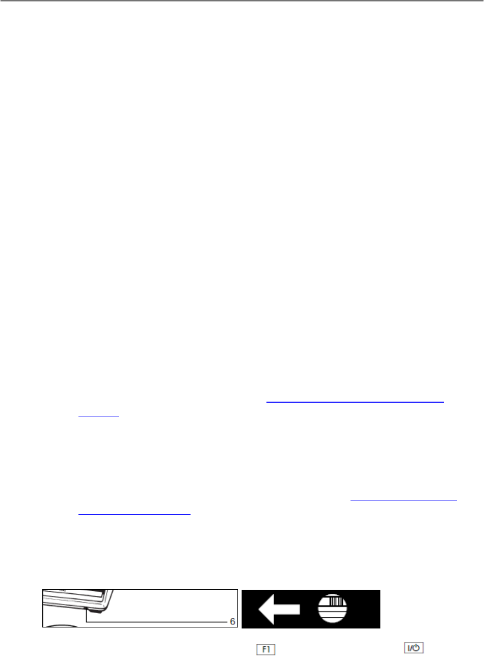
August 2019 Section 9: Analytical Balance Use
FRMAC Fly Away Laboratory Manual 9-9
• The built-in calibration weight is applied automatically.
• The balance is calibrated.
• If configured for CALIBRATE THEN AUTO ADJUST IN ONE OPERATION is selected in
Setup menu (1 10 1; factory setting), the balance is now adjusted automatically.
• The internal calibration weight is removed.
NOTE: In the Setup menu, you can configure whether:
• Calibration is always followed automatically by adjustment (1 10 1), or
• You have the choice of ending the sequence or starting adjustment after Calibration
(1 10 2). If no difference is determined between nominal and actual weights, you can
end the calibration/adjustment routine following calibration. Two keys are active at
the point:
o (CAL) = start calibration/adjustment
o (CF) = end the sequence
9.2.9.2 Adjustment/Calibration for PT3100
[Manufacturer Operating Manual, page 8; balance logbook]
The PT3100 balance does not have an internal, automatic calibration/adjustment feature; this
function is performed using a single, external, calibrated 1,000 g weight.
1. Identify and obtain the appropriate certified test weight for the balance to be tested.
a. For the PT3100 balance, with a single-range of 0-3,100 g, use 1 each 1 kg weight.
b. Certified test weights with an expired calibration and/or certification shall be
labeled conspicuously on the exterior case “Do Not Use,” and shall be removed
from further service. Notify the Laboratory Test Lead and ensure that, when
possible, the weight is calibrated (See Section 9.6.2, Annual Calibration of
Weights).
c. Wearing gloves, examine the test weight for cleanliness and damage (e.g., nicks,
scratches, etc.). As needed, carefully dust the certified test weight with a dry, lint-
free cloth to remove any foreign matter. If damage is found, clearly note on the
exterior case “Do Not Use,” and remove the weight from further service. Notify
the Laboratory Test Lead and ensure that, when possible, the weight is repaired (if
feasible – or replaced), re-certified, and calibrated (See Section 9.6.2, Annual
Calibration of Weights).
During calibration with a calibration weight, the sensitivity of the balance is adjusted to
changes in ambient conditions.
11. Remove the protective cap located on the front right of the balance and slide the access
switch (6) in the direction of the arrow
12. With the balance turned off, hold down the key and briefly press the key.

August 2019 Section 9: Analytical Balance Use
FRMAC Fly Away Laboratory Manual 9-10
Upon completion of the automatic self-test, release the key as soon as the “C” is
displayed (upper right corner of display).
13. Unload the balance and press the tare control (7) to zero the display.
14. When the display shows a zero readout, press the key. “CAL” and the calibration
weight readout will now be displayed.
15. Center the 1,000 g calibration weight on the weighing pan, and then the balance self-
calibrates automatically. The end of the calibration/adjustment is indicated by the weight
unit symbol that appears on the display.
16. Relock the calibration access function by sliding the access switch back to its original
setting (to the left), and replace the protective cap.
17. After calibration, use the key to turn the balance off and then on again so that you
have direct access again to the weighing mode.
9.3 Daily Linearity, Reproducibility, and Accuracy Checks
9.3.1 Linearity Checks
Linearity testing verifies the accuracy of the instrument at intermediate values of weight. The
balance linearity test measures the ability of the balance to accurately measure an added weight
before and after a non-measured weight load has been placed on the balance. Prior to operation,
on a daily basis, follow the Linearity Check procedure outlined below. Record results on the

August 2019 Section 9: Analytical Balance Use
FRMAC Fly Away Laboratory Manual 9-11
“Daily Linearity Check Log” record sheet (see Section 9.7.2, Daily Linearity and Accuracy
Checks Log).
The procedure is as follows:
1. Identify and obtain the appropriate certified test weights for the balance to be tested
(see Table 9.1). Use two sets of weights, each of approximately one-half the weighing
capacity of the balance. It is imperative that these two weights not be interchanged
within this procedure. These two weights are referred to as “weight A” and “weight
B.”
Table 9.1: Weights for Linearity Check
Weight Range
PT3100
CPA6202P
CPA1003P
0 – 3100 g
1 kg + 500 g
0 – 3000 g
1 kg + 500 g
3000 – 6200 g
2 x 2 kg
0 – 500 g
200 g
500 – 1010 g
500 g + 200 g
a. Certified test weights with an expired calibration and/or certification shall be
labeled conspicuously on the exterior case “Do Not Use” and shall be removed
from further service. Notify the Laboratory Test Lead and ensure that, when
possible, the weight is calibrated (See Section 9.6.2, Annual Calibration of
Weights).
b. Wearing gloves, examine the test weight for cleanliness and damage (e.g., nicks,
scratches, etc.). As needed, carefully dust the certified test weight with a dry, lint-
free cloth to remove any foreign matter. If damage is found, clearly note on the
exterior case “Do Not Use,” and remove the weight from further service. Notify
the Laboratory Test Lead and ensure that, when possible, the weight is repaired (if
feasible, or replaced), re-certified, and calibrated (See Section 9.6.2, Annual
Calibration of Weights).
18.
19. Re-zero (tare) the display. Place “A” on the pan (at the center) and record the reading on
the “Linearity Chart” in the column marked “0% - 50%.”
20. Remove “A” and place “B” on the pan (at the center). Re-zero (tare) the display with “B”
still on the pan. Again place “A” on the pan, with “B” still on the pan. Record the reading
under the column marked “50% - 100%.”Calculate the difference between the two (0%-
50% & 50%-100%) readings. The difference should be less than the linearity tolerances
for each balance and range:
• PT3100: ± 0.2 g
• CPA6202P, 0-3,000 g: ± 0.02 g / 3,000-6,200 g: ± 0.05 g
• CPA1003P, 0-500 g: ± 0.001 g / 500-1,010 g: ± 0.01 g
9.3.2 Reproducibility Checks
Reproducibility testing entails repeatedly weighing a given object, recording the results, and
analyzing those results. Prior to operation, on a daily basis, follow the Linearity Check procedure
outlined below. A test weight equal to, or nearly equal to, the weighing capacity of the
instrument should be selected.

August 2019 Section 9: Analytical Balance Use
FRMAC Fly Away Laboratory Manual 9-12
Twenty pairs of readings should be taken for 2 data sets: “full-scale reading” and “zero reading.”
Record results on the Daily Reproducibility Check Log record sheet (see Section 9.7.3, Weekly
Reproducibility Check Log).
A detailed procedure is as follows:
1. Identify and obtain the appropriate certified test weights for the balance to be tested
(see Table 9.2).
Table 9.2: Weights for Reproducibility Check
Weight Range
PT3100
CPA6202P
CPA1003P
0 – 3100 g
2 kg, 1 kg
0 – 3000 g
2 kg, 1 kg
3000 – 6200 g
3 x 2 kg
0 – 500 g
500 g
500 – 1010 g
1 kg
a. Certified test weights with an expired calibration and/or certification shall be
labeled conspicuously on the exterior case “Do Not Use” and shall be removed
from further service. Notify the Laboratory Test Lead and ensure that, when
possible, the weight is calibrated (See Section 9.6.2, Annual Calibration of
Weights).
b. Wearing gloves, examine the test weight for cleanliness and damage (e.g., nicks,
scratches, etc.). As needed, carefully dust the certified test weight with a dry, lint-
free cloth to remove any foreign matter. If damage is found, clearly note on the
exterior case “Do Not Use,” and remove the weight from further service. Notify
the Laboratory Test Lead and ensure that, when possible, the weight is repaired (if
feasible, or replaced), re-certified, and calibrated (See Section 9.6.2, Annual
Calibration of Weights).
2. Tare the instrument to read all zeros. Do not record the initial zero reading.
3. Place the test weight on the pan. Record the reading in the column labeled “FULL
SCALE READING.”
4. Remove the weight (do not rezero), and record the reading under “ZERO READING.”
5. Repeat steps 2 and 3 until lines 1 through 10 are all filled in.
6. Transcribe the 2 columns of numbers into the Reproducibility Check spreadsheet.
7. Use the Reproducibility Check spreadsheet to calculate the standard deviation and
coefficient of variation (CV) of both columns of numbers.
8. Calculated standard deviations larger than allowed in the instrument specifications
indicate that the instrument is either operating in an unstable environment (static, air
draft, warm-up, vibration, etc.), or that the instrument is in need of repair:
▪ PT3100: ± 0.1 g
▪ CPA6202P, 0-3,000 g: ± 0.01 g / 3,000-6,200 g: ± 0.03 g
▪ CPA1003P, 0-500 g: ± 0.001 g / 500-1,010 g: ± 0.01 g

August 2019 Section 9: Analytical Balance Use
FRMAC Fly Away Laboratory Manual 9-13
9.3.3 Accuracy Checks
Prior to each measurement process, on a daily basis, verify balance accuracy for a target sample.
This verification is performed using the closest estimated certified weight as follows:
1. Identify and obtain the appropriate balance binder/log for the balance to be used.
2. Check the calibration sticker on the balance and weight set to ensure the calibration is
current.
3. Clean the balance pan and weighing chamber of residual dust and drippings.
4. Check the balance level indicator. The bubble should be within the black outlined
circle. Readjust the leveling feet if necessary.
5. Zero the balance by pressing the tare bar.
6. Place the required certified weight (the closest to the estimated weight to be measured)
on the balance pan. Wait for the balance to be stabilized and record the result in the
balance logbook. Remove the weight from the balance pan.
7. The allowable control limit is ± 0.1% of the certified weight value across the entire
weight range. Notify the Laboratory Team Lead if the balance fails to pass the
accuracy test. Place a conspicuous “Out of Order” sign on the balance and follow the
procedures outlined in Section 9.2.9, Calibration/Adjustment.
9.3.4 Action for Linearity, Reproducibility or Accuracy Check Failure
1. Perform a calibration/adjustment on the balance (see Section 9.2.9,
Calibration/Adjustment) if daily linearity, reproducibility, or accuracy checks fail.
2. Repeat linearity, reproducibility, and accuracy checks if a calibration/adjustment is
performed.
3. If the balance continues to fail linearity, reproducibility, or accuracy checks, remove
the balance from service.
9.4 Procedure
9.4.1 Weighing Samples
Refer to the balance manufacturer’s operating instructions for specific procedures on the proper
operating techniques unique to that particular balance.
9.4.1.1 CPA1003P with Draft Shield
To weigh an unknown:
1. Verify successful completion of operational accuracy check for balance/measurement
process.
2. Clean the balance pan and weighing chamber of residual dust and drippings.
3. Check the balance level indicator. The bubble should be within the black outlined
circle. Readjust the leveling feet if necessary.
4. Ensure that the glass doors of the weighing chamber are completely closed.
5. Turn the display on and carefully watch the automatic digital readout demonstration.

August 2019 Section 9: Analytical Balance Use
FRMAC Fly Away Laboratory Manual 9-14
6. If any segment fails to light during the readout demonstration, place an “Out of Order”
sign on the balance, and follow the procedures outlined in Section 9.2.9,
Calibration/Adjustment.
7. Zero the balance by pressing the tare bar.
8. Display subsequently indicates zero (weighing mode). The number of decimal places
depends on the readability of the balance as well as the selected weighing range. The
balance is now ready to weigh an unknown.
9. Open a door on the weighing chamber and carefully place the unknown on the balance
pan.
10. Close the weighing chamber door.
11. Wait for stability and read the results.
9.4.1.2 Top-Loading Balance
To weigh an unknown:
1. Verify successful completion of operational accuracy check for balance/measurement
process.
2. Clean the balance pan of residual dust and drippings.
3. Check the balance level indicator. The bubble should be within the black outlined
circle. Readjust the leveling feet if necessary.
4. Turn the display on by briefly pressing the control/tare bar.
5. If any segment fails to light during the readout demonstration, place an “Out of Order”
sign on the balance, and follow the procedures outlined in Section 9.2.9,
Calibration/Adjustment.
6. Zero the balance by pressing the tare bar.
7. Display subsequently indicates zero (weighing mode). The number of display digits
depends on the readability of the balance as well as the selected weighing range. The
balance is now ready to weigh an unknown.
8. Carefully place the unknown on the balance pan.
9. Wait for the stability and record the result.
9.4.2 Taring
To tare an item:
1. Place the container on the balance pan.
2. Briefly press the tare bar.
3. The container has now been tared. The weighing range minus the tare weight is now
available for weighing.
9.5 Preparation for Transport
Care must be taken in preparing the balances, weights, and associated components for transport
to ensure they will be operationally ready for subsequent deployments.

August 2019 Section 9: Analytical Balance Use
FRMAC Fly Away Laboratory Manual 9-15
9.5.1 Preparation of Balances for Transport
To prepare a balance for transport:
1. De-energize balance (See Section 9.2.8, Energizing/De-energizing).
2. Disconnect power cord and AC adapter.
3. Clean balance (all) and draft shield (CPA1003P) (See Section 9.6.4, Balance
Cleaning).
4. Before disassembling and packing balances and associated components, check each
immediately for any visible damage as a result of mishaps during weighing operations.
If this is the case, proceed as directed in Section 9.6.3, Safety Inspection.
5. Disassemble each balance by reversing the processes covered in Section 9.2.4,
Assembly.
6. Carefully re-pack each balance and associated components back into their transport
cases. Be sure to handle the balances only from the sides or base; do not grab the
sensitive component area on top of the balance.
9.5.2 Preparation of Weights for Transport
Care must be taken in preparing the balances, weights, and associated components for transport
to ensure they will be operationally ready for subsequent deployments. Improper storage and/or
prolonged contact with moisture, fingerprints, or other foreign matter may damage or invalidate
the calibration of the weights.
To prepare certified weights for transport:
1. Inspect each weight for any visible damage. If any is found, remove it from service and
make note of this in the Annual Calibration and Maintenance Log (see Section 9.6.1,
Annual Calibration and Maintenance of Balances). When possible, have the weight
serviced by trained personnel. If the damage is excessive, the weight needs to be
replaced.
2. Wearing gloves, wipe each weight with a clean, dry cloth.
3. Place each weight into its individual storage case; then, place each storage case into the
weight set transport case.
9.6 Maintenance
9.6.1 Annual Calibration and Preventative Maintenance of Balances
1. On an annual basis, ensure that preventative maintenance and calibration is performed for
each balance by a certified vendor.
2. Upon completion of the annual preventative maintenance and calibration, inspect each
balance (see Section 9.6.3, Safety Inspection) and then verify calibration certificate and
stickers.
3. Place the new calibration certificate in the associated balance binder.

August 2019 Section 9: Analytical Balance Use
FRMAC Fly Away Laboratory Manual 9-16
9.6.2 Annual Calibration of Weights
1. On an annual basis, ensure that preventative maintenance and calibration is performed for
each weight by a certified vendor.
2. Upon completion of the annual preventative maintenance and calibration, inspect each
weight and then verify calibration certificate and stickers.
3. Place the new calibration certificate in the certified weight set binder.
9.6.3 Safety Inspection
If there is any indication that safe operation of the balance is no longer warranted:
1. Turn off the power and disconnect the equipment from AC power immediately.
2. Label the equipment as out-of-service and lock it in a secure place to ensure that it cannot
be used until the safety issue has been resolved. Notify the Fly Away Laboratory
Manager .
3. When possible, have the equipment repaired by trained service technicians.
9.6.4 Balance Cleaning
Cleaning the Balance Housing
1. Unplug the AC adapter from the wall outlet.
2. Clean the balance using a piece of cloth that has been wetted with a mild detergent (soap)
solution.
c. Make sure that no liquid or other foreign objects or dust (powder) enters the
balance housing.
d. Do not use any aggressive cleaning agents (solvents or similar agents).
21. After cleaning, wipe down the balance with a soft, dry cloth.
Cleaning Stainless Steel Surfaces
1. Clean all stainless steel parts regularly.
2. Remove the stainless steel weighing pan and thoroughly clean it separately.
3. Use a damp cloth or sponge to clean any stainless steel parts on the balance by wiping
them down. You can use any commercially available household cleaning agent that is
suitable for use on stainless steel. Then wipe down the equipment to rinse thoroughly,
making sure to remove all residues.
4. Afterwards, allow the balance to dry.
5. If desired, you can apply oil to the cleaned stainless steel surfaces as additional
protection. Solvents are permitted for use only on stainless steel parts.
Cleaning the Weighing Chamber and Draft Shield
1. Open the draft shield cover and take out the removable parts.
2. Use a hand-held vacuum cleaner and mini-hose to remove any powdered sample material
carefully.
3. Use blotting paper to remove any liquid sample material.

August 2019 Section 9: Analytical Balance Use
FRMAC Fly Away Laboratory Manual 9-17
9.7 Records
9.7.1 Calibration /Adjustment Log
• PT3100
• CPA1003P
• CPA 62002P
9.7.2 Daily Linearity and Accuracy Checks Log
• PT3100
• CPA1003P
• CPA 62002P
9.7.3 Weekly Reproducibility Check Log
• PT3100
• CPA1003P
• CPA 62002P
9.8 Balance Specifications
Table 9.3: Balance Specifications
Manufacturer
Series
Model
Sartorius Portable
PT3100
Sartorius CP
CPA1003P
Sartorius
CP
CPA6202P
Weighing Capacity g
3,100
500/1,010
1,500/3,000/6,200
Readability g
0.1
0.001/0.01
0.01/0.02/0.05
Tare Range (by subtraction) g
-3,100
-1,010
-6,200
Repeatability, Standard Deviation ≤±g
0.1
0.001/0.01
0.01/0.01/0.03
Maximum Linearity ≤±g
0.2
0.002/0.02
0.02/0.02/0.05
Response time (average) s
1.5
≤ 2
≤1.5
Display update at stability (depends on the filter
level selected) s
0.1; 0.2; 0.4
**
**
Display update when load on pan changes s
0.1
**
**
Adaptation to operating requirements and
ambient conditions
By selection of 1
of 3 optimized
filter levels
**
**
Stability range d
0.25…32
(selectable)
**
**
Operating temperature range °C
**
10° to 30° (50°
to 86°F)
10° to 30° (50° to 86°F)
Allowable operating ambient temperature
273-313 K
(0°C…+40°C)
0° to 40°C (32°
to 104°F)
0° to 40°C (32° to 104°F)
Allowable relative humidity %
15…85 (non-
condensing)
**
**
Sensitivity Drift within +10 to +30°C
1.5E-05 /°C
≤± 2E-06 /K
≤± 2E-06 /K

August 2019 Section 9: Analytical Balance Use
FRMAC Fly Away Laboratory Manual 9-18
Manufacturer
Series
Model
Sartorius Portable
PT3100
Sartorius CP
CPA1003P
Sartorius
CP
CPA6202P
External calibration weight (of at least accuracy
class…) g
**
1,000 (E2)
5,000 (F1)
Weighing pan size mm
Weighing pan area cm
174x133
231
110 (inner dia.)
120
190x204
388
Weighing chamber height (weighing pan to draft
shield cover) mm
**
240
**
Balance housing (WxDxH) mm
185x215x55
213x342x340
213x342x88
Net weight, approx. kg
1.2
6.5
4.7
AC power requirements V~
115 V, 50-60 Hz
AC adapter
STNG6, 230 V
or 115 V, 48-
60Hz
AC adapter STNG6, 230 V
or 115 V, 48-60Hz
Allowable voltage fluctuation
-20%...+15%
-20%...+15%
-20%...+15%
This page is intentionally left blank

August 2019 Section 10: Data Handling and Verification/Validation
FRMAC Fly Away Laboratory Manual 10-1
Section 10: Data Handling and Verification/Validation
1. Review the final report against the analysis request form for the following
information:
o Sample ID Numbers
o Customer Name
o Sample Type
o Sample Description
o Sample Aliquot
o Sample Units
o Sample Date/Time
o ARF Number
o Count Time
o Sample Geometry
o Unidentified Peak Report (if applicable)
o Appropriate Gamma Library
o Analytical Method (e.g. LSC, GPC or Gamma)
o Analyst ID
o Comments
2. Next perform a technical review of the final report.
o Once the report is reviewed and acceptable, sign and date the report.
o Check the final report against the Electronic Data Deliverable (EDD).
o Provide the entire package to the FAL Manager for final review.
o Once the FAL Manager approves the data, forward a hardcopy along with the
EDD to the customer.

August 2019 Section 10: Data Handling and Verification/Validation
FRMAC Fly Away Laboratory Manual 10-2
This page is intentionally left blank

August 2019 Appendix A: iSOCS
TM
Geometry Composer Tutorial
FRMAC Fly Away Laboratory Manual A-1
Appendix A: iSOCS™ Geometry Composer Tutorial
Introduction
A wide variety of sample configurations are analyzed with portable gamma spectral systems
such as the FALCON™ 5000. Qualitative analysis results can be quantified by utilizing the
CANBERRA ISOCS™ code in conjunction with the standard ISOCS™ and/or LabSOCS™
geometry templates. Efficiency calibration files can be created for specific counting scenarios.
Below is a step by step job aid that will enable the laboratory staff to model a counting geometry
and obtain qualitative analysis results.
Procedure
1. You must use an ISOCS™ CALIBRATED DETECTOR for analysis!!!
2. In the Canberra ISOCS/LabSOCS™ Manual, choose the geometry template that best
suits the shape or geometry of the sample being analyzed.
3. Open the Geometry Composer from the Genie2000 folder on the desktop: select
FILE→ OPEN and select the appropriate template.
NOTE: If you are using a pre-defined geometry, press the edit dimensions button to “edit
dimensions” of the geometry.
Below is an example of the template provided in the ISOCS™ program that allows you to input
material and source dimensions. Based on the drawing, input the proper dimensions and
materials here. Be mindful of units.
If a material that matches (or is very close to) the material being analyzed is not listed in the pull-
down menu, the “mu editor” can be used to create new materials in the library.
Below is an example of the “mu editor” window.

August 2019 Appendix A: iSOCS
TM
Geometry Composer Tutorial
FRMAC Fly Away Laboratory Manual A-2
If the elemental mass ratios are known for the material, it can be defined by using the element
selection box to the left. The atomic ratios of each molecule can be input using the “n =”
selection box. For example: Water consists of two hydrogen atoms attached to one oxygen atom.
To enter this, select H from the box, increase “n =” so that it equals 2, and then push the up
arrow. To add the oxygen, select O from the list, change “n=” to 1, and then press the up arrow.
If the matrix consists only of water, then the mass percentage would be 100. If there was salt in
the water, then the mass ratio would have to be calculated and the salt would have to be added
separately.
Alternatively, you can make a new substance by combining any ratio of the materials in the
library using the utility at the right of the screen.
Once the new material is listed in the center box and the “Component Balance” is equal to 0, you
must enter the mass density of the material, give it a name, and enter an optional comment to
help identify the material. By clicking the SAVE INTO LIBRARY button, the new material is saved
to the library and can be used in any future models.
a. Once the correct dimensions and materials have been selected, the efficiency
codes are ready to be executed.
b. Check geometry validity by pressing this button: . This utility checks the
geometrical parameters to make sure that a logical model has been created. Error
messages are usually self-explanatory, and you will be able to figure out how to
fix the problem. For errors that are not easily understood, refer to the Canberra
ISOCS™ Manual.
c. Modify or load energy list by pressing this button:
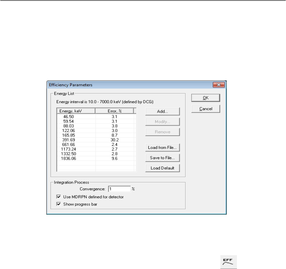
August 2019 Appendix A: iSOCS
TM
Geometry Composer Tutorial
FRMAC Fly Away Laboratory Manual A-3
Below is an example of the utility that allows you to modify the energy list. With
this utility, you can choose the energies for which the code will calculate
efficiencies. For most applications, the default energy list is adequate.
A rule of thumb is to be sure that there are at least 10 data points and that
both the lowest and highest gamma energy of all the nuclides of interest are
within the bounds of the energies selected. Just like the mu editor, the energy
list can be saved and loaded into future models.
d. Save the model with a name similar to 03_FAL_geoname replacing geoname with
a descriptive name of the geometry and 03 with the detector number. Save the file
in C:\GENIE2K\isocs\data\GEOMETRY folder. Take note of where you saved
the file.
e. To run the efficiency calculator press the following button:
f. Select FILE →PRINT to print out the geometry report. Retain this as part of the
record.
4. To use the newly developed efficiency curve, open GENIE2K.
a. Open Gamma Acquisition & Analysis (from the Genie 2000 folder on the
desktop).
b. FILE → OPEN DATA SOURCE: Select the CNF. File of the spectrum that is to be
analyzed with the iSOCS™ geometry.
c. Select CALIBRATE → EFFICIENCY → BY LABSOCS/ISOCS…
d. Select the model that was just performed (.ecc file) Geometry Composer.
e. Select NEXT >.
f. Select EFFICIENCY unless instructed otherwise.
g. Select NEXT >.
h. Select SHOW…

August 2019 Appendix A: iSOCS
TM
Geometry Composer Tutorial
FRMAC Fly Away Laboratory Manual A-4
i. Select LINEAR as the curve type unless instructed otherwise. Ensure that all of the
datapoints lie very close to the calculated curve fit. Print the chart in both linear
and log scales and attach this to the geometry composer report. If a point needs to
be dropped from the fit, select LIST PKS… and drop points as necessary. When
satisfied with the fit, select PRINT for both the Log and Linear Scale. Select OK to
commit the calibration to the file.
j. Select REPORT… Print this report, and attach it to the geometry composer report
and the graphs of the efficiency curve.
k. STORE the calibration. Be sure to include information in the filename that points
to what detector and geometry it pertains to. Be sure that the first character in the
filename matches the detector number for which the model was created. For
example, if a water cube was modeled on FAL03, then the filename should read
something similar to “3waterbox.CAL.”
l. Select FINISH.
m. Associate the calibration with γ RATS by launching the program and expanding
the NON-ROUTINE section at the bottom of the window. Select the desired model,
enter a name for the geometry (needs to match the name of the geoname created
earlier). Press SET CALIBRATION.
n. Assemble the iSOCS™ report, the efficiency calibration report, the calibration
graphs and attach to the Gamma Spectroscopy ISOCS Calibration cover sheet
found in Appendix B.
o. Fill out the Gamma Spectroscopy ISOCS Calibration cover sheet with the
detector ID, the .CAL and the .GEO Calibration file names, and the date the
model was created. Record the sample matrix (e.g. Soil, water, etc.) the degree of
fullness, and any other description of the contents that is pertinent to the model.
Make a detailed sketch of the geometry including all the pertinent dimensions.
Sign and date the Modeled by field.
NOTE: The degree of fullness field is for any indication of sample quantity. It can be sample fill
height, percent full, volume, etc.
p. Have the calibration packet reviewed by another experienced gamma
spectroscopist for completeness and correctness. File with the other calibration
reports.

June, 2012 Appendix B: Fly Away Laboratory Forms
FRMAC Fly Away Laboratory Manual B-1
Appendix B: Fly Away Laboratory Forms
This page is intentionally left blank

June, 2012 Appendix B: Fly Away Laboratory Forms
FRMAC Fly Away Laboratory Manual B-2
PORTABLE GAMMA SPECTROSCOPY
CALIBRATION
Detector ID:
Manufacturer and Serial No.:
Archive File Names:
Source IDs:
Calibration Date:
CHECK LIST
All Calibration Packages shall include the following items:
Peak Search Results Energy and Shape Calibration
Energy and FWHM Report and Graphs
Peak Search Results Efficiency Calibrations
Efficiency Calibration Reports and Graphs
Source Certificates
Calibration verification package
Reviewed By: Date:
Approved By: Date:

June, 2012 Appendix B: Fly Away Laboratory Forms
FRMAC Fly Away Laboratory Manual B-3
GAMMA SPECTROSCOPY
ISOCS CALIBRATION
Detector ID:
Calibration File Names:
Modeling Date:
CHECK LIST
All Calibration Packages shall include the following items:
ISOCS Report
Efficiency Calibration Reports and Graphs
Sample Information and Sketch
Sample Matrix:
Degree of Fullness:
Description of Contents:
Sketch of Geometry:
Modeled By: Date:
Reviewed By: Date:

June, 2012 Appendix B: Fly Away Laboratory Forms
FRMAC Fly Away Laboratory Manual B-1

June, 2012 Appendix B: Fly Away Laboratory Forms
FRMAC Fly Away Laboratory Manual B-2

June, 2012 Appendix B: Fly Away Laboratory Forms
FRMAC Fly Away Laboratory Manual B-3

June, 2012 Appendix B: Fly Away Laboratory Forms
FRMAC Fly Away Laboratory Manual B-4

June, 2012 Appendix B: Fly Away Laboratory Forms
FRMAC Fly Away Laboratory Manual B-5

June, 2012 Appendix B: Fly Away Laboratory Forms
FRMAC Fly Away Laboratory Manual B-6

June, 2012 Appendix B: Fly Away Laboratory Forms
FRMAC Fly Away Laboratory Manual B-7

August, 2019 Appendix C: Interferences and Limitations
FRMAC Fly Away Laboratory Manual C-1
Appendix C: Interferences and Limitations
Limitations for AIR FILTERS ONLY
To determine if there is alpha activity (excluding Radon and Thoron daughters) on an air filter
soon after it has been removed from the air flow, the filter needs to be counted for 2 minutes to
determine the gross level of activity. It then needs to be recounted for 10 minutes to more
accurately determine the activity.
The background subtract algorithm does not always give a result of ‘zero’ dpm if there is no
activity on the filter.
The algorithm was tested by sampling with two filters overnight in a clean room and reading the
filters in the morning. The test was repeated 5 times. Results are shown below. Note that the 2-
minute count results varied from –120 to +10 dpm. Therefore, given the algorithm subtracts 120
dpm as background, it would be possible to have 120 dpm of Pu on the filter and have the result
indicate ‘0 dpm.’ Longer count times lessen the likelihood of not reporting ‘real’ activity.
Table 7.1: Estimated Background Rates
Length of count following a
1 to 3 day sampling interval
Bkgd results for ‘clean’ air
(dpm)
2 min
-120 to +10
10 min
-50 to +40
30 min
-15 to +5
60 min
-1 to +10
NOTE: 5 dpm represents 0.6 DAC-hr of Class W
239
Pu and 0.2 DAC-hr of Class Y
239
Pu
(assuming air flow sampling rate of 30 lpm)
