
Page i
Bug Tracking and Reporting System
Project Report submitted in partial fulfillment of the requirement for the degree
of Bachelors of Technology.
In Computer Science & Engineering under the Supervision of
Dr. Yashwant Singh
by
Ojas Agarwal (111476)
To
Jaypee University of Information and Technology
Waknaghat, Solan – 173234, Himachal Pradesh

Page ii
Certificate
This is to certify that project report entitled “Bug Tracking and reporting system”, submitted by Ojas
Agarwal in partial fulfillment for the award of degree of Bachelor of Technology in Computer Science &
Engineering to Jaypee University of Information Technology, Waknaghat, Solan has been carried out under
my supervision.
This work has not been submitted partially or fully to any other University or Institute for the award of this
or any other degree or diploma.
Date: 15
th
May 2015 Dr. Yashwant Singh
Assistant Professor

Page iii
Acknowledgement
I express thanks and gratitude to Almighty God, my parents and other family members and friends without
whose uncontained support; I could not have made this career in CSE.
I wish to place on my record my deep sense of gratitude to my project guide Dr. Yashwant Sigh, for his
constant motivation and valuable help throughout the project work. I also extend my thanks to other
Faculties for their Cooperation during my Course.
Finally I would like to thank my friends for their cooperation to complete this project.
Date: 15
th
May 2015 Ojas Agarwal

Page iv
ABSTRACT
Bug-Tracking mechanism is employed only is some of the large software development houses. Most of
the others never bothered with bug tracking at all, and instead simply relied on shared lists and email to
monitor the status of defects. This procedure is error-prone and tends to cause those bugs judged least
significant by developers to be dropped or ignored.
Bug-Tracking System is an ideal solution to track the bugs of a product, solution or an application. Bug
Tacking System allows individual or groups of developers to keep track of outstanding bugs in their product
effectively. This can also be called as Defect Tracking System.
The Bug Tracking System can dramatically increase the productivity and accountability of individual
employees by providing a documented work flow and positive feedback for good performance.

Page v
Table of Contents
Acknowledgement ............................................................................................................ i
Abstract .......................................................................................................................... ii
Table of Contents ........................................................................................................... iv
List of Figures ................................................................................................................. v
List Of Photoes ............................................................................................................... vi
1. Introduction............................................................................................................... 1
1.1 Problem Statement ....................................................... Error! Bookmark not defined.
1.2 Existing System ........................................................... Error! Bookmark not defined.
1.3 Proposed System(Contribution).................................................................................... 2
2. Feasibility Study and LR.......................................................................................... 3
2.1 Technical feasibility ..................................................................................................... 3
2.2 Economic feasibility ..................................................................................................... 3
2.3 Operational feasibility .................................................................................................. 3
2.4 Literature Survey .......................................................................................................... 4
3. Software Requirements Analysis ............................................................................. 5
3.1 Overview ...................................................................................................................... 5
3.2 Problem Description .................................................................................................... 5
3.3 Solution ......................................................................................................................... 6
3.4 Modules ........................................................................................................................ 6
3.5 Module Description ...................................................................................................... 6
4. Software Design ........................................................................................................ 7
4.1. Data Flow Diagram ........................................................................................... 7
4.1.1 Context Level DFD ........................................................................................ 8
4.1.2 Top Level DFD .............................................................................................. 9
4.2 UML Diagrams .................................................................................................. 10
4.2.1 Class Diagram .............................................................................................. 11
4.2.2 Interaction Diagram ...................................................................................... 12
4.2.2.1 Sequence Diagram............................................................................... 12
4.2.2.2 Collaboration Diagram ........................................................................ 16
4.2.3 Use case Diagram ......................................................................................... 18
4.2.4 Component Diagram .................................................................................... 22
4.2.5 Deployment Diagram ................................................................................... 22

Page vi
4.3 Control Flow Diagrams ....................................................................................... 24
4.3.1 Activity Diagram .......................................................................................... 24
4.4 Database Design ................................................................................................. 28
4.4.1 E-R Diagram ................................................................................................ 28
5. Implementation………………………………………………………………… 30
6. Testing…………………………………………………………………………… 37
Snapshots……..………………………………………………………………… 39
7. Conclusion and future works ................................................................................. 43
8. Bibliography .............................................................................................................. 44
9. Appendix…………..………………………………………………………………45

Page vii
List of Figures
Fig No Fig Name Pages
Fig. 4.1 Context Level DFD 8
Fig. 4.2 Top Level DFD 9
Fig 4.3 Class Diagram 11
Fig 4.4 Administration Sequence Diagram 13
Fig 4.5 Manager Sequence 14
Fig 4.6 Employee Sequence 15
Fig 4.7 Administrative Collaboration 16
Fig 4.8 Manager Collaboration 17
Fig 4.9 Employee collaboration 17
Fig 4.10 Overall Use case Diagram 18
Fig 4.11 Administrator Use case 19
Fig 4.12 Manager Use case 20
Fig 4.13 Employee Use case 21
Fig 4.14 Component Diagram 22
Fig 4.15 Deployment Diagram 23
Fig 4.16 Login Activity Diagram 24
Fig 4.17 Registration Activity Diagram 25
Fig 4.18 Manager Activity Diagram 26
Fig 4.19 Administrator Process 27
Fig 4.20 Employee Process 28
Fig 4.21 ER-Diagram 29

Page 1
CHAPTER 1
1. Introduction
This project is aimed at developing an online defect tracking system useful for applications developed in an
organization. The Defect Tracking System (DTS) is a web based application that can be accessed throughout
the organization. This system can be used for logging defects against an application/module, assigning
defects to individuals and tracking the defects to resolution. There are features like email notifications, user
maintenance, user access control, report generators etc in this system.
The software is fully integrated with CRM (Customer Relationship Management) as well as CMS (Content
Management System) solution and developed in a manner that is easily manageable, time saving and
relieving one from manual works.
1.1 Problem Statement
The main objective of this system is develop flawless system, which is access real time information
from anywhere in the world, 24 hours a day 365 days in a year. Another aim is that manage hundred of
projects in multiple locations or just a few. Another main objective of this system is track the all the defects
or bugs in the project and make the project user friendly and bugs free system.
1.2 Existing System
In any software development bugs are inevitable. Let it be in any kind of product bugs arise at any
phase of development. One has to take a great care in the proper maintenance and resolution of the bugs. In
the Existing system the bugs are not properly maintained and they are simply relied on shared lists and email
to monitor the bugs.
In this type of system it becomes difficult to track a bug if a bug is over looked then it may cause
tremendous errors in the next phase and can improve the cost of project whatever necessary effort spent on
the bug maintenance may not be worthy. So bug history has to be maintained properly. And there is no
efficient search technique.
One has to search the whole database for the details of particular bug which might have occurred
sometime earlier. It is both time consuming and error prone. And it is very difficult to share the bug among
several users as there is no proper maintenance of the bugs. In order to have an efficient product bugs must
be maintained properly and should be resolved in time both to reduce time and money spent on the
development.

Page 2
1.3 Contribution
This system maintains the products, Bugs and bug Tracking. It has advantage of maintaining bug
history it stores all the details from bug origin to bug resolution.
Each product can have versions for easy maintenance of the product and all the user of the product is
stored in the database. It provides the advantage of maintaining users to the bugs and resolutions
provided by them.
Our System provides the searching based on status, priority, and operating system.
It provides with user and bug hierarchy, which would be helpful in knowing the relation between
bugs and users allotted to the bug.
It is provided with a fully authenticated system with password encryption. And has the facility for
storing attachments for a bug.
One can keep a track of the bug in a product with much lower cost and effort.
The most advantage of this system is maintaining log records which are helpful in knowing any
errors or misuse of the system by other users.
1.4 Objectives
To track the status level of the project.
To track the status level of each bug in the project module.
To assign the projects to the users by administration.
To add the bugs by the administration.
To add the status, severity levels by the admin.
To add a detailed bug information.
To add the modules in the project and to track the person developing it.
1.5 Project Outline
Chapter 2 contains feasibility analysis and literature review.
Chapter 3 contains software requirement analysis.
Chapter 4 contains design of the project.
Chapter 5 contains the information about tools that were used to make this project
Chapter 6 contains the testing information.
After chapter 6 we have a few sample snapshots of the implemented project.
Chapter 7 contains bibliography.
Appendix contains sample code of the important parts of the project.

Page 3
CHAPTER 2
Feasibility Study and Literature Review
2.1 Technical Feasibility
A set of programs associated with the operation of a computer is called software. Software is the part of
the computer system which enables the user to interact with several physical hardware devices.
The minimum software requirement specifications for developing this project are as follows:
Designing frontend : HTML, CSS
Backend : PHP, MySQL
Scripting : Java Script
UML : Rational Rose
IDE : My Eclipse
Web Server : Wamp
The Collection of internal electronic circuits and external physical devices used in building a computer is
called Hardware.
The minimum hardware requirement specification for developing this project is as follows:
Processor : Pentium IV
RAM : 512MB RAM
Hard Disk : 10GB
2.2 Economic feasibility
There is increased customer satisfaction, improvement in product quality, better decision making, increased
speed, improved accuracy better documentation.
2.3 Operational feasibility
This system increases the likelihood of a successful project.

Page 4
2.4 Behavioral feasibility
To err is human. There can always be a mistake while adding project record manually in an excel sheet. It is
a tedious task to add bugs, periodically change their status, and it will always be prone to errors. This
software aims to find a solution to this. So this is behaviorally feasible.

Page 5
CHAPTER 3
3. Software Requirements Analysis
3.1 Overview
The main focus of the analysis phase of Software development is on “What needs to be done”. The
objects discovered during the analysis can serve as the framework or Design. The class’s attributes, methods
and association identified during analysis must be designed for implementation language. New classes must
be introduced to store intermediate results during the program execution.
3.2 Problem Description
One has to take a great care in the proper maintenance and resolution of the bugs. In the Existing
system the bugs are not properly maintained and they are simply relied on shared lists and email to monitor
the bugs.
In this type of system it becomes difficult to track a bug if a bug is over looked then it may cause
tremendous errors in the next phase and can improve the cost of project whatever necessary effort spent on
the bug maintenance may not be worthy. So bug history has to be maintained properly. And there is no
efficient search technique.
One has to search the whole database for the details of particular bug which might have occurred
sometime earlier. It is both time consuming and error prone. And it is very difficult to share the bug among
several users as there is no proper maintenance of the bugs. In order to have an efficient product bugs must
be maintained properly and should be resolved in time both to reduce time and money spent on the
development.
3.3 Solution
This system maintains the products, Bugs and bug tracking. It has advantage of maintaining bug
history it stores all the details from bug origin to bug resolution. Each product can have versions for easy
maintenance of the product and all the user of the product is stored in the database. It provides the advantage
of maintaining users to the bugs and resolutions provided by them. Our System provides the searching based
on status, priority, and operating system. It provides with user and bug hierarchy, which would be helpful in
knowing the relation between bugs and users allotted to the bug. It is provided with a fully authenticated
system with password encryption. And has the facility for storing attachments for a bug. One can keep a
track of the bug in a product with much lower cost and effort. The most advantage of this system is
maintaining log records which are helpful in knowing any errors or misuse of the system by other users.

Page 6
3.4 Modules
1. Tester
2. Manager
3. Administrator
4. Developer
5. Report
3.5 Module Description
Tester
Tester can access to the projects or bugs assigned by the manager, can view the assigned projects and
can add a new bug to the list and send the bug back to the manager. Tester can login to the system and access
the assigned project list.
Manager
Manager takes care of recruitment of employees and the management of employees in the project and
monitors the completion of project. He has full access to the particular project assigned by the admin and
controls the team members acess to the bugs assigned. Has the permission to generate the reports and update
the info of team members and adding members to the project.
Administrator
Administrator is a person who will take care of all registration status, acceptance of new bugs, and
many other tasks to reduce burden on employee. He has the entire access to all the other modules. Admin
creates the project and assigning the projects to the created manager, adding members to the managers,
assigning bugs based on the priority.
Report
Both admin and manager can access this module and generate the reports based on the requirements.

Page 7
CHAPTER 4
4. Software Design
The main focus of the analysis phase of Software development is on “What needs to be done”. The
objects discovered during the analysis can serve as the framework or Design. The class’s attributes, methods
and association identified during analysis must be designed for implementation language. New classes must
be introduced to store intermediate results during the program execution.
Emphasis shifts from the application domain of implementation and computer such as user interfaces or
view layer and access layer. During analysis, we look at the physical entities or business objects in the
system, that is, which players and how they cooperate to do the work of the application. These objects
represent tangible elements of the business.
During the Design phase, we elevate the model into logical entities, some of which might relate more to
the computer domain as people or employees. Here his goal is to design the classes that we need to
implement the system the difference is that, at this level we focus on the view and access classes, such as
how to maintain information or the best way o interact with a user or present information.
Design process:
During the design phase the classes identified in object-oriented analysis Must be revisited with a shift
focus to their implementation. New classes or attribute and Methods must be an added for implementation
purposes and user interfaces.
The following are some of the vies of software design life cycle. They are
Data Flow Diagrams
UML Diagrams
Data Base Design
4.1 Data Flow Diagram
A Data Flow Diagram (DFD) is a graphical representation of the “flow” of data through an information
system. It can also be used for the visualization of data processing (structured design).
There are two types of DFDs. They are:
Context Level DFD
Top Level DFD
Page 8
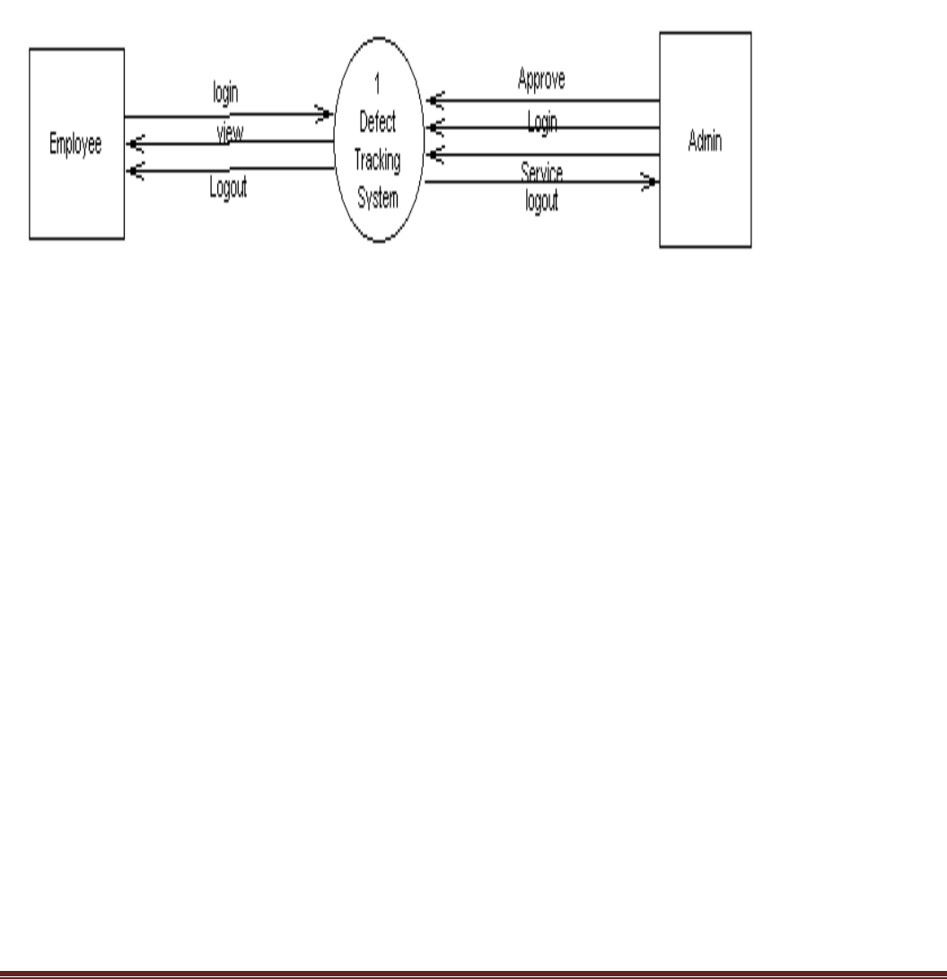
4.1.1 Context Level DFD
In the Context Level the whole system is shown as a single process.
No data stores are shown.
Inputs to the overall system are shown together with data sources (as External entities).
Outputs from the overall system are shown together with their destinations (as External entities).
Fig. 4.1 Context Level DFD
4.1.2 Top Level DFD
The Top Level DFD gives the overview of the whole system identifying the major system processes and
data flow. This level focuses on the single process that is drawn in the context diagram by ‘Zooming in’ on
its contents and illustrates what it does in more detail.

Page 9
Fig. 5.2 Top Level DFD
4.2 UML Diagrams
Unified Modeling Language
The Unified Modeling Language allows the software engineer to express an analysis model using the
modeling notation that is governed by a set of syntactic semantic and pragmatic rules.
This UML diagrams must include the following:
Class diagram
Interaction Diagram
Use case Diagram
Activity Diagram
Component Diagram

Page 10
Deployment Diagram
Class Diagrams
The class diagram is the main building block in object oriented modeling. They are being used both for
general conceptual modeling of the systematic of the application, and for detailed modeling translating the
models into programming code.
The classes in a class diagram represent both the main objects and or interactions in the application and
the objects to be programmed. In the class diagram these classes are represented with boxes which contain
three parts:
The upper part holds the name of the class
The middle part contains the attributes of the class, and
The bottom part gives the methods or operations the class can take or undertake
An Activity Diagram shows the flow from activity to activity.
An activity is an ongoing non- atomic execution within a state machine.

Page 11
4.2.1Class Diagrams
Fig 4.3 Class Diagram

Page 12
4.2.2 Interaction Diagram
Interaction Diagrams
An interaction diagram shows an interaction, consisting of a set of objects and their relationships,
including the messages that may be dispatched among them.
A sequence diagram is an interaction diagram that emphasizes the time ordering of messages. Graphically,
a sequence diagram is a table that shows objects arranged along x-axis and messages, ordered in increasing
time, along the y-axis.
A Collaboration is a society of classes, interfaces, and other elements that work together to provide some
cooperative behavior that’s bigger than the sum of all its parts.
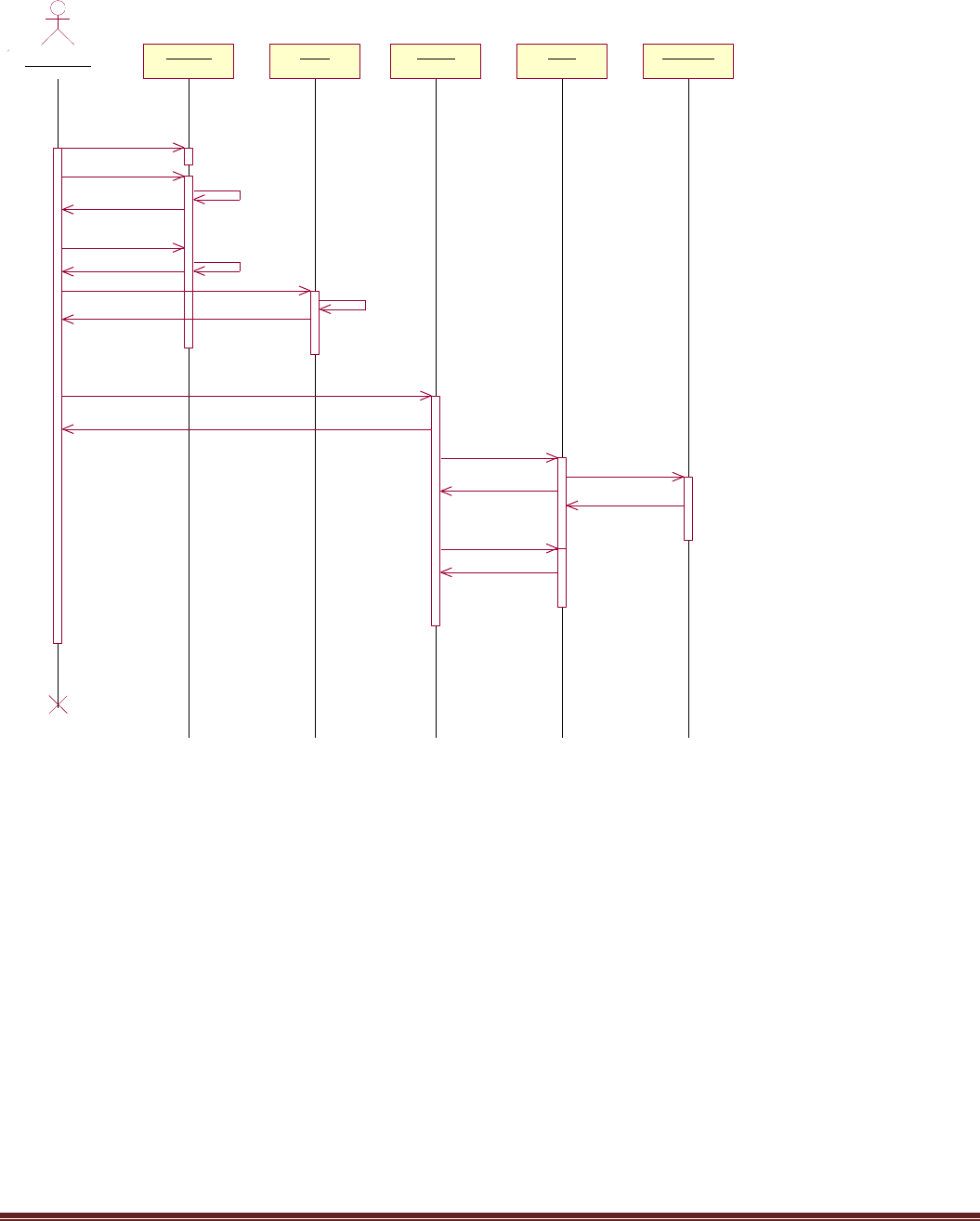
4.2.2.1 Sequence Diagram
An interaction diagram shows an interaction, consisting of a set of objects and their relationships,
including the messages that may be dispatched among them.
A sequence diagram is an interaction diagram that emphasizes the time ordering of messages.
Graphically, a sequence diagram is a table that shows objects arranged along x-axis and messages,
ordered in increasing time, along the y-axis.
Contents
Sequence diagrams commonly contain the following:
Objects
Links
Messages
Like all other diagrams, sequence diagrams may contain notes and constrains.

Page 13
Fig 4.4 Administration Sequence Diagram
: Administrator
Login Permission Manager Employee ProjectDepartment
1: loginrequest()
validation
response()
2: Create()
response()
3: create()
valid()
confirmation()
4: create()
confirmation()
valid()
5: view()
6: view()

Page 14
Fig 4.5 Manager Sequence
: Manager
Register Login Department Project Monitor
1: Fill up the details
submit()
verfication()
confirmation()
3: login request()
validation
response()
4: create()
5: allot department()
response()
6: Allot project()
response()
7: monitor
response()
Page 15
Fig 4.6 Employee Sequence
: Employee
Register Login Project Bugs Test Plan
1:Fill up the details
Developer()
Tester()
Confirmation()
Confirmation()
Verfication
Verification
2: Login Request()
Validation
response()
3: employee selects alloted project()
response()
4: Tester identify bugs()
5: tester develop testplan
employee rectify bugs
confirmation()
submit to developer
submit to developer

Page 16
4.2.2.2 Collaborations Diagram
Collaboration is a society of classes, interfaces, and other elements that work together to provide some
cooperative behavior that’s bigger than the sum of all its parts.
Collaboration is also the specification of how an element, such as a classifier or an operation, is realized
by a set of classifiers and associations playing specific roles used in a specific way
Contents
Collaboration diagrams commonly contain the following:
Objects
Links
Messages
Like all other diagrams, sequence diagrams may contain notes and constrains.
Fig 4.7 Administrative Collaboration
: Administrator
Login
Permissio
n
Manager
Employee
Project
Departme
nt
2: validation
7: valid()
10: valid()
1: 1: loginrequest()
3: response()
12: 5: view()
13: 6: view()
4: 2: Create()5: response()
6: 3: create()
8: confirmation()
9: 4: create()
11: confirmation()

Page 17
Fig 4.8 Manager Collaboration
Fig 4.9 Employee collaboration
: Manager
Register
Login
Departme
nt
Project
Monitor
3: verfication()
6: validation
1: 1: Fill up the details
2: submit()
4: confirmation()
5: 3: login request()
7: response()
11: 6: Allot project()
12: response()
13: 7: monitor
14: response()
8: 4: create()
9: 5: allot department()
10: response()
Register
Login
Project
: Employee
Bugs
Test Plan
3: Verfication
6: Verification
9: Validation
13: 4: Tester identify bugs()
17: employee rectify bugs
15: submit to developer
18: confirmation()
1: 1:Fill up the details
2: Developer()
5: Tester()
7: Confirmation()
4: Confirmation()
8: 2: Login Request()
10: response()
11: 3: employee selects alloted project()
12: response()
14: 5: tester develop testplan
16: submit to developer

Page 18
4.2.3 Use case Diagram
A use case diagram is a diagram that shows a set of use cases and actors and relationships.
Use case Diagrams represent the functionality of the system from a user’s point of view. Use cases are
used during requirements elicitation and analysis to represent the functionality of the system .Use cases
focus on the behavior of the system from external point of view.
Fig 4.10 Overall Use case Diagram
Developer
Tester
Validation
Bugs
Testplan
Employee
Administrator
Login
<<include>>
Project
Department
Monitor
Manager

Page 19
Fig 4.11 Administrator Use case
Developers
Testers
Login
Project
Department
Create Employee
Create Manager
Logout
Permission
Administrator

Page 20
Fig 4.12 Manager Use case
Developers
Testers
Login
Register
Project
Department
Monitor
Logout
Employees
Manager

Page 21
Fig 4.13 Employee use case
Tester
Developer
Login
Register
Project
Bugs
Testplan
Logout
Employee

Page 22
4.2.4 Component Diagram
Fig 4.14 Component Diagram
4.2.5 Deployment Diagram
A deployment diagram is a diagram that shows the configuration of run time processing nodes and the
components that live on them.
Graphically, a deployment diagram is collection of vertices and arcs.
Contents
Deployment diagram commonly contain the following things:
Nodes
Dependency and association relationships
Like all other diagrams, deployment diagrams may contain notes and constraints.
Deployment diagrams may also contain components, each of which must live on some node.
Deployment diagrams may also contain packages or subsystems, both of which are used to group
elements of your model into larger chunks.
manager Projects
Employee
Developer
Tester
Bugs/Te
stplan
Database JDBC

Page 23
Fig 4.15 Deployment Diagram
USER
Web
Browser
Servlets
Application
Application Server
J2SE
Server
Database Server
MySQL Server

Page 24
4.3 Control Flow diagrams
4.3.1 Activity Diagram
An activity diagram shows the flow from activity to activity. An activity is an ongoing non-atomic execution
within a state machine.
Activities ultimately result in some action, which is made up of executable atomic computations that
result in a change in state of the system or the return of a value.
Activity diagrams commonly contain
Activity states and action states
Transitions
Objects
Like all other diagrams, activity diagrams may contain notes and constrains
Login Process
Providing
Credentials
Validation
Retry
Services
<<No>>
<<YES>>
Fig 4.16 Login Activity Diagram

Page 25
Registration Process
Fig 4.17 Registration Activity Diagram
Manager Process
Fig 4.18 Manager Activity Diagram
Providing
examination
admin validation
Invalidate
details
<<NO>>
Provide
Credentials
<<YES>>
Login
Validation
Projects
Monitor
Department
Create/upd
ate/delete
Logout

Page 26
Administrator Process
Fig 4.19 Administrator Process
Login
validation
Employee Manager Projects
Department
View
Create/upd
ate/delete
Permission
Logout

Page 27
Employee Process
Fig 4.20 Employee Process
Employee
Developer
Tester
Login
validation
Projects
Bugs
Testplan
select
create
update delete
create
delete
update
Login
Logout
Rectify

Page 28
4.4 Database Design
Database design is the process of producing a detailed data model of a database. This logical data
model contains all the needed logical and physical design choices and physical storage parameters needed to
generate a design in a Data Definition Language, which can then be used to create a database. A fully
attributed data model contains detailed attributes for each entity.
The term database design can be used to describe many different parts of the design of an
overall database system. Principally, and most correctly, it can be thought of as the logical design of the base
data structures used to store the data. In the relational model these are the tables and views.
In an object database the entities and relationships map directly to object classes and named
relationships. However, the term database design could also be used to apply to the overall process of
designing, not just the base data structures, but also the forms and queries used as part of the overall database
application within the database management system (DBMS).
4.4.1 ER-Diagrams
Entity Relationship Diagrams (ERDs) illustrate the logical structure of databases. An entity-relationship
(ER) diagram is a specialized graphic that illustrates the interrelationships between entities in a database.
ER diagrams often use symbols to represent three different types of information. Boxes are commonly
used to represent entities. Diamonds are normally used to represent relationships and ovals are used to
represent attributes.
Entity relationship diagrams are a way to represent the structure and layout of a database. It is used
frequently to describe the database schema. ER diagrams are very useful as provide a good conceptual view
of any database, regardless of the underlying hardware and software.
Page 29
Fig 4.21 ER-Diagram
Employee
ECode: INTEGER
FName: VARCHAR(45)
LName: VARCHAR(45)
Gender: VARCHAR(45)
DOB: DATE
Qualification: VARCHAR(45)
Address: VARCHAR(100)
Phone_Number: INTEGER
Mobile: INTEGER
EMail_Id: VARCHAR(45)
DOJ: DATE
Basic_Salary: INTEGER
DNo: INTEGER
Login_Id: VARCHAR(45)
Password: VARCHAR(45)
Marital_Status: VARCHAR(45)
Hint_Question: VARCHAR(45)
Hint_Answer: VARCHAR(45)
Role: VARCHAR(45)
Department
Dept_Number: INTEGER
Dept_Name: VARCHAR(45)
Dept_Location: VARCHAR(45)
Project
Project_Number: INTEGER
Project_Name: VARCHAR(45)
Project_Description: VARCHAR(45)
SDate: DATE
Duration: INTEGER
Client_Name: VARCHAR(45)
Client_Address: VARCHAR(45)
Client_Phone: VARCHAR(45)
Client_EMail: VARCHAR(45)
Project_Lead: VARCHAR(45)
Dept_Name: VARCHAR(45)
Assign_Project
SNo: INTEGER
Project_Name: VARCHAR(45)
User_Id: VARCHAR(45)
Role: VARCHAR(45)
Bug_Report
Bug_No: INTEGER
Bug_Name: VARCHAR(45)
Bug_Type: VARCHAR(45)
Bug_Level: VARCHAR(45)
Priority: VARCHAR(45)
Project_Name: VARCHAR(45)
Tester_Code: VARCHAR(45)
Bug_Date: VARCHAR(45)
E_Code: VARCHAR(45)
Status: VARCHAR(45)
Bug_Rectified_Date: VARCHAR(45)
Stauts: VARCHAR(45)

Page 30
CHAPTER 5
5. IMPLEMENTATION
5.1 General
A programming tool or software tool is a program or application that software developers use to
create, debug, maintain, or otherwise support other programs and applications. The term usually refers to
relatively simple programs that can be combined together to accomplish a task. The Chapter describes about
the software tool that is used in our project.
5.2. HTML
HTML, an initialism of Hypertext Markup Language, is the predominant markup language for web
pages. It provides a means to describe the structure of text-based information in a document — by denoting
certain text as headings, paragraphs, lists, and so on — and to supplement that text with interactive forms,
embedded images, and other objects. HTML is written in the form of labels (known as tags), surrounded by
angle brackets. HTML can also describe, to some degree, the appearance and semantics of a document, and
can include embedded scripting language code which can affect the behavior of web browsers and other
HTML processors.
HTML is also often used to refer to content of the MIME type text/html or even more broadly as a generic
term for HTML whether in its XML-descended form (such as XHTML 1.0 and later) or its form descended
directly from SGML
1.1.1.1.1.1.1 Hyper Text Markup Language
Hypertext Markup Language (HTML), the languages of the World Wide Web (WWW), allows users to
produces Web pages that include text, graphics and pointer to other Web pages (Hyperlinks).
HTML is not a programming language but it is an application of ISO Standard 8879, SGML (Standard
Generalized Markup Language), but specialized to hypertext and adapted to the Web. The idea behind
Hypertext is that instead of reading text in rigid linear structure, we can easily jump from one point to
another point. We can navigate through the information based on our interest and preference. A markup
language is simply a series of elements, each delimited with special characters that define how text or other
items enclosed within the elements should be displayed. Hyperlinks are underlined or emphasized works that
load to other documents or some portions of the same document.

Page 31
HTML can be used to display any type of document on the host computer, which can be geographically at a
different location. It is a versatile language and can be used on any platform or desktop.
HTML provides tags (special codes) to make the document look attractive. HTML tags are not case-
sensitive. Using graphics, fonts, different sizes, color, etc., can enhance the presentation of the document.
Anything that is not a tag is part of the document itself.
Basic HTML Tags:
<! -- --> specifies comments
<A>……….</A> Creates hypertext links
<B>……….</B> Formats text as bold
<BIG>……….</BIG> Formats text in large font.
<BODY>…</BODY> Contains all tags and text in the HTML document
<CENTER>...</CENTER> Creates text
<DD>…</DD> Definition of a term
<DL>...</DL> Creates definition list
<FONT>…</FONT> Formats text with a particular font
<FORM>...</FORM> Encloses a fill-out form
<FRAME>...</FRAME> Defines a particular frame in a set of frames
<H#>…</H#> Creates headings of different levels( 1 – 6 )
<HEAD>...</HEAD> Contains tags that specify information about a document
<HR>...</HR> Creates a horizontal rule
<HTML>…</HTML> Contains all other HTML tags
<META>...</META> Provides meta-information about a document
<SCRIPT>…</SCRIPT> Contains client-side or server-side script
<TABLE>…</TABLE> Creates a table
<TD>…</TD> Indicates table data in a table

Page 32
<TR>…</TR> Designates a table row
<TH>…</TH> Creates a heading in a table
5.2.1 Attributes
The attributes of an element are name-value pairs, separated by "=", and written within the start label of an
element, after the element's name. The value should be enclosed in single or double quotes, although values
consisting of certain characters can be left unquoted in HTML (but not XHTML).Leaving attribute values
unquoted is considered unsafe.
Most elements take any of several common attributes: id, class, style and title. Most also take language-
related attributes: lang and dir.
The id attribute provides a document-wide unique identifier for an element. This can be used by stylesheets
to provide presentational properties, by browsers to focus attention on the specific element or by scripts to
alter the contents or presentation of an element. The class attribute provides a way of classifying similar
elements for presentation purposes. For example, an HTML document (or a set of documents) may use the
designation class="notation" to indicate that all elements with this class value are all subordinate to the main
text of the document (or documents). Such notation classes of elements might be gathered together and
presented as footnotes on a page, rather than appearing in the place where they appear in the source HTML.
An author may use the style non-attributal codes presentational properties to a particular element. It is
considered better practice to use an element’s son- id page and select the element with a stylesheet, though
sometimes this can be too cumbersome for a simple ad hoc application of styled properties. The title is used
to attach subtextual explanation to an element. In most browsers this title attribute is displayed as what is
often referred to as a tooltip. The generic inline span element can be used to demonstrate these various non-
attributes.
The preceding displays as HTML (pointing the cursor at the abbreviation should display the title text in most
browsers).
5.2.2 Advantages
A HTML document is small and hence easy to send over the net. It is small because it does not
include formatted information.
HTML is platform independent.
HTML tags are not case-sensitive.

Page 33
5.3 Database
A database management system (DBMS) is computer software designed for the purpose of managing
databases, a large set of structured data, and run operations on the data requested by numerous users. Typical
examples of DBMSs include Oracle, DB2, Microsoft Access, Microsoft SQL Server, Firebird, PostgreSQL,
MySQL, SQLite, FileMaker and Sybase Adaptive Server Enterprise. DBMSs are typically used by Database
administrators in the creation of Database systems. Typical examples of DBMS use include accounting,
human resources and customer support systems.
Originally found only in large companies with the computer hardware needed to support large data sets,
DBMSs have more recently emerged as a fairly standard part of any company back office.
5.3.1 Description
A DBMS is a complex set of software programs that controls the organization, storage, management, and
retrieval of data in a database. A DBMS includes:
A modeling language to define the schema of each database hosted in the DBMS, according to the
DBMS data model.
The four most common types of organizations are the hierarchical, network, relational and object
models. Inverted lists and other methods are also used. A given database management system
may provide one or more of the four models. The optimal structure depends on the natural
organization of the application's data, and on the application's requirements (which include
transaction rate (speed), reliability, maintainability, scalability, and cost).
The dominant model in use today is the ad hoc one embedded in SQL, despite the objections of
purists who believe this model is a corruption of the relational model, since it violates several of
its fundamental principles for the sake of practicality and performance. Many DBMSs also
support the Open Database Connectivity API that supports a standard way for programmers to
access the DBMS.
Data structures (fields, records, files and objects) optimized to deal with very large amounts of data
stored on a permanent data storage device (which implies relatively slow access compared to volatile
main memory).
A database query language and report writer to allow users to interactively interrogate the database,
analyze its data and update it according to the users privileges on data.
It also controls the security of the database.

Page 34
Data security prevents unauthorized users from viewing or updating the database. Using
passwords, users are allowed access to the entire database or subsets of it called subschemas. For
example, an employee database can contain all the data about an individual employee, but one
group of users may be authorized to view only payroll data, while others are allowed access to
only work history and medical data.
If the DBMS provides a way to interactively enter and update the database, as well as interrogate
it, this capability allows for managing personal databases. However, it may not leave an audit
trail of actions or provide the kinds of controls necessary in a multi-user organization. These
controls are only available when a set of application programs are customized for each data entry
and updating function.
A transaction mechanism, that ideally would guarantee the ACID properties, in order to ensure data
integrity, despite concurrent user accesses (concurrency control), and faults (fault tolerance).
It also maintains the integrity of the data in the database.
The DBMS can maintain the integrity of the database by not allowing more than one user to
update the same record at the same time. The DBMS can help prevent duplicate records via
unique index constraints; for example, no two customers with the same customer numbers (key
fields) can be entered into the database. See ACID properties for more information (Redundancy
avoidance).
The DBMS accepts requests for data from the application program and instructs the operating system to
transfer the appropriate data.
When a DBMS is used, information systems can be changed much more easily as the organization's
information requirements change. New categories of data can be added to the database without disruption to
the existing system.
Organizations may use one kind of DBMS for daily transaction processing and then move the detail onto
another computer that uses another DBMS better suited for random inquiries and analysis. Overall systems
design decisions are performed by data administrators and systems analysts. Detailed database design is
performed by database administrators.
Database servers are specially designed computers that hold the actual databases and run only the DBMS
and related software. Database servers are usually multiprocessor computers, with RAID disk arrays used for
stable storage. Connected to one or more servers via a high-speed channel, hardware database accelerators
are also used in large volume transaction processing environments.

Page 35
DBMSs are found at the heart of most database applications. Sometimes DBMSs are built around a private
multitasking kernel with built-in networking support although nowadays these functions are left to the
operating system.
5.4 SQL
Structured Query Language (SQL) is the language used to manipulate relational databases. SQL is tied very
closely with the relational model.
In the relational model, data is stored in structures called relations or tables.
SQL statements are issued for the purpose of:
Data definition: Defining tables and structures in the database (DDL used to create, alter and drop schema
objects such as tables and indexes).
Data manipulation: Used to manipulate the data within those schema objects (DML Inserting, Updating,
Deleting the data, and Querying the Database).
A schema is a collection of database objects that can include: tables, views, indexes and sequences
List of SQL statements that can be issued against an Oracle database schema are:
ALTER - Change an existing table, view or index definition (DDL)
AUDIT - Track the changes made to a table (DDL)
COMMENT - Add a comment to a table or column in a table (DDL)
COMMIT - Make all recent changes permanent (DML - transactional)
CREATE - Create new database objects such as tables or views (DDL)
DELETE - Delete rows from a database table (DML)

Page 36
DROP - Drop a database object such as a table, view or index (DDL)
GRANT - Allow another user to access database objects such as tables or views (DDL)
INSERT - Insert new data into a database table (DML)
No AUDIT - Turn off the auditing function (DDL)
REVOKE - Disallow a user access to database objects such as tables and views (DDL)
ROLLBACK - Undo any recent changes to the database (DML - Transactional)
SELECT - Retrieve data from a database table (DML)
TRUNCATE - Delete all rows from a database table (can not be rolled back) (DML)
UPDATE - Change the values of some data items in a database table (DML)

Page 37
CHAPTER 6 (TESTING)
The aim of testing is often to demonstrate that a program works by showing that it has no errors. The basic
purpose of testing phase is to detect the errors that may be present in the program. Hence, one should not
start the testing with the intent of showing that a program works; but the intent should be to show that a
program does not work. In short, it is the process of executing a program with the intent of finding errors.
9.1 Types of testing
There are two basic approaches to testing
FUNCTIONAL TESTING
STRUCTURAL TESTING
Functional testing – This type of testing ignores the internal parts and focus on the output is as per
requirement or not. Black-box type testing geared to functional requirements of an application.
Structural testing- The structural testing is the testing of the structure of the system or component.
Structural testing is often referred to as ‘white box’ or ‘glass box’ or ‘clear-box testing’ because in structural
testing we are interested in what is happening ‘inside the system/application’.
In structural testing the testers are required to have the knowledge of the internal implementations of the
code. Here the testers require knowledge of how the software is implemented, how it works.
Besides these, there are a number of other testing techniques.
Unit testing – Testing of individual software components or modules. Typically done by the programmer
and not by testers, as it requires detailed knowledge of the internal program design and code. may require
developing test driver modules or test harnesses.
Incremental integration testing – Bottom up approach for testing i.e continuous testing of an application as
new functionality is added; Application functionality and modules should be independent enough to test
separately. done by programmers or by testers.
Integration testing – Testing of integrated modules to verify combined functionality after integration.
Modules are typically code modules, individual applications, client and server applications on a network, etc.
This type of testing is especially relevant to client/server and distributed systems.

Page 38
Functional testing – This type of testing ignores the internal parts and focus on the output is as per
requirement or not. Black-box type testing geared to functional requirements of an application.
System testing – Entire system is tested as per the requirements. Black-box type testing that is based on
overall requirements specifications, covers all combined parts of a system.
End-to-end testing – Similar to system testing, involves testing of a complete application environment in a
situation that mimics real-world use, such as interacting with a database, using network communications, or
interacting with other hardware, applications, or systems if appropriate.
Sanity testing – Testing to determine if a new software version is performing well enough to accept it for a
major testing effort. If application is crashing for initial use then system is not stable enough for further
testing and build or application is assigned to fix.
Regression testing – Testing the application as a whole for the modification in any module or functionality.
Difficult to cover all the system in regression testing so typically automation tools are used for these testing
types.
Acceptance testing -Normally this type of testing is done to verify if system meets the customer specified
requirements. User or customer do this testing to determine whether to accept application.
Load testing – Its a performance testing to check system behavior under load. Testing an application under
heavy loads, such as testing of a web site under a range of loads to determine at what point the system’s
response time degrades or fails.
Stress testing – System is stressed beyond its specifications to check how and when it fails. Performed
under heavy load like putting large number beyond storage capacity, complex database queries, continuous
input to system or database load.
Performance testing – Term often used interchangeably with ‘stress’ and ‘load’ testing. To check whether
system meets performance requirements. Used different performance and load tools to do this.
Usability testing – User-friendliness check. Application flow is tested, Can new user understand the
application easily, Proper help documented whenever user stuck at any point. Basically system navigation is
checked in this testing.

Page 39
Sample Snapshots:
Home Screen
Admin Homepage

Page 40
Project details
Add Manager

Page 41
Developer view
Tester View

Page 42

Page 43
7. CONCLUSION AND FUTURE WORKS
Making this project on “Bug tracking and Reporting” has been a very fulfilling experience. Working long
hours every day to for 2 semesters was a tedious job but rewarding in the end. I never was very good t web
development. But I had to study from different very interesting books on php and web designing that it is no
more a challenge for me.
The skills learned through this project can be summarized as
Thorough knowledge of backend especially php.
Deal with complex CSS templates.
Understand software engineering through hands on experience.
In future I would like to add a data mining feature in the project where this application will detect any
duplicate bugs that a tester might try to add. It will test for keywords in the description of the bug and decide
if a similar bug is already in the database.

Page 44
8. BIBLIOGRAPHY
Bell, S. (2003). An Analysis and Design of Information Systems. Routledge.
Davis, W. S., & Yen, D. C. (1998). System Analysis And Design. CRC Press.
Devi, N., Aarthi, S., & Fyaz, A. S. (2013). Bug Tracking and Reporting System. International Journal of Soft Computing
and Engineering (IJSCE) , 4.
Price, J. (2007). Database Management System. McGraw-Hill Osborne Media.
Schach. (2007). Software Engineering. McGraw-Hill Science/Engineering/Math.
William S. Davis, D. C. (2007). System Analysis and Design. CRC books.

Page 45
APPENDIX
Login:
<?php
include 'connect.php';
session_start();
$username = $_POST['username'];
$password = $_POST['password'];
$role = $_POST['role'];
$query= mysqli_query($con,"SELECT * From table_bug WHERE User_Name='$username' and
Password='$password' and Role='$role'");
$numrows = mysqli_num_rows($query);
if ($numrows!=0)
{
while ($row = mysqli_fetch_assoc($query))
{
$dbusername = $row['User_name'];
$dbpassword = $row['Password'];
}
if($username==$dbusername&&$password==$dbpassword)
{
// session_start();
$_SESSION['username']=$username;
$_SESSION['role']=$role;
$_SESSION['stime']= date("Y-m-d H:i:s");
echo "Success!";
}
else
echo "Incorrect password!";
}
else
echo "That user does't exist!";
?>

Page 46
Connect:
<?php
$server = 'localhost';
$username = 'root';
$password = '';
$database = 'ojass';
$con = mysqli_connect($server, $username, $password);
if(!mysqli_connect($server, $username, $password))
{
exit('Error: could not establish database connection');
}
if(!mysqli_select_db($con,$database))
{
exit('Error: could not select the database');
}
?>
Home:
<?php
if($_SESSION['role']=="admin")
{
$query= mysqli_query($con,"SELECT * From project1");
?>
<table>
<thead>
<tr>
<th>id</th>
<th>name</th>
<th>manager</th>
<th>client</th>
</tr>
</thead>
<tbody>

Page 47
<?php
while ($row = mysqli_fetch_assoc($query)){
?>
<tr class='clickableRow' href='detail.php?id=<?php echo $row['Id']; ?>'>
<td><?php echo $row['Id']; ?></td>
<td><?php echo $row['Name']; ?></td>
<td><?php echo $row['Manager']; ?></td>
<td><?php echo $row['Client']; ?></td>
</tr></a>
<?php } ?>
</tbody>
</table>
<?php }
else if($_SESSION['role']=="manager")
{ $username = $_SESSION['username'];
$q2= "SELECT * From project1 where Manager ='$username' ";
$query2= mysqli_query($con,$q2);
// $query2= mysqli_query($con,"SELECT * From project where Manager ='$username'");
?>
<table>
<thead>
<tr>
<th>id</th>
<th>name</th>
<th>client</th>
</tr>
</thead>
<tbody>
<?php
$numrows2 = mysqli_num_rows($query2);
while($row2 = mysqli_fetch_assoc($query2)){
?>

Page 48
<tr class='clickableRow' href='detail.php?id=<?php echo $row2['Id']; ?>'>
<td><?php echo $row2['Id']; ?></td>
<td><?php echo $row2['Name']; ?></td>
<td><?php echo $row2['Client']; ?></td>
</tr></a>
<?php } ?>
</tbody>
</table>
<?php
}
else
{
?>
<table>
<thead>
<tr>
<th>id</th>
<th>name</th>
<th>manager</th>
<th>developer</th>
<th>tester</th>
<th>client</th>
<th>status</th>
<th>start date</th>
<th>bug id</th>
</tr>
</thead>
<tbody>
<?php
$username = $_SESSION['username'];
$role = $_SESSION['role'];
$q= "SELECT * From project where Manager ='$username' OR Developer = '$username' OR
Tester = '$username' ";

Page 49
$query1= mysqli_query($con,$q);
$numrows = mysqli_num_rows($query1);
//echo $numrows;
while ($row1 = mysqli_fetch_assoc($query1)){
?>
<tr class='clickableRow' href='detail.php?id=<?php echo $row1['Id']; ?>'>
<td><?php echo $row1['Id']; ?></td>
<td><?php echo $row1['Name']; ?></td>
<td><?php echo $row1['Manager']; ?></td>
<td><?php echo $row1['Developer']; ?></td>
<td><?php echo $row1['Tester']; ?></td>
<td><?php echo $row1['Client']; ?></td>
<td><?php echo $row1['Status']; ?></td>
<td><?php echo $row1['Start_date']; ?></td>
<td><?php echo $row1['Bug_id']; ?></td>
</tr></a>
<?php
}
}
?>
</tbody>
</table>
<?php
$role = $_SESSION['role'];
if($role == "developer")
{
$q3= "SELECT * From bug where Developer = '$username'";
$query3= mysqli_query($con,$q3);
$numrows3 = mysqli_num_rows($query3);
//echo $numrows;
?>
<table>
<thead>

Page 50
<tr>
<th>Bug id</th>
<th>Name</th>
<th>ID</th>
<th>Severity</th>
<th>Description</th>
<th>status</th>
</tr>
</thead>
<tbody>
<?php
while ($row3 = mysqli_fetch_assoc($query3))
{
?>
<tr class='clickableRow' href='detail.php?id=<?php echo $row3['Id']; ?>'>
<td><?php echo $row3['Bug_id']; ?></td>
<td><?php echo $row3['Name']; ?></td>
<td><?php echo $row3['Id']; ?></td>
<td><?php echo $row3['Severity']; ?></td>
<td><?php echo $row3['Description']; ?></td>
<td><?php echo $row3['Status']; ?></td>
</tr></a>
<?php
}
}
?>
</tr>
</tbody>
</table>

Page 51
Add Manager:
<?php
session_start();
include 'connect.php';
$name= $_POST['name'];
$id= $_POST['id'];
$query= mysqli_query($con,"UPDATE project SET Manager='$name' where Id='$id'");
$query1= mysqli_query($con,"UPDATE project1 SET Manager='$name' where Id='$id'");
$query2= mysqli_query($con,"SELECT Email From table_bug where User_name='$name'");
$row = mysqli_fetch_assoc($query2);
$to = $row['Email'];
$subject = 'YOu have been appointed as manager to a new project';
$message = 'Work hard';
$headers = 'From: [email protected]' . "\r\n" .
'Reply-To: [email protected]' . "\r\n" .
'X-Mailer: PHP/' . phpversion();
mail($to, $subject, $message, $headers);
$newurl = "home.php";
header('Location: ' . $newurl);
?>
