
HITACHI Printer
Instruction Manual
INK JET PRINTER FOR INDUSTRIAL MARKING
Model RX2
Thank you for purchasing the Hitachi IJ Printer Model RX2.
This printer employs a noncontact, ink-jet method to print onto a print target.
This instruction manual describes the basic operating procedures, maintenance procedures, and other detailed
handling procedures of the Hitachi IJ Printer Model RX2.
If the printer is improperly handled or maintained, it may not operate smoothly and may become defective or
cause an accident. It is therefore essential that you read this manual to gain a complete understanding of the
printer and use it correctly.
After thoroughly reading the manual, properly store it for future reference.
IF you changed the language of the screen by mistake, see Chapter 7.8 "Selecting Languages".
●Safety Precautions (1)
SAFETY PRECAUTIONS
● Before using the printer, thoroughly read the following safety precautions for optimum printer
use.
● You should observe the precautions set forth below in order to use the product properly and
avoid endangering you or other persons or damaging property. For the purpose of clarifying
the severity of injury or damage and likelihood of occurrence, the precautions are classified
into two categories, WARNING and CAUTION, which both describe hazardous situations
that may arise if you ignore the precautions and perform an incorrect handling or operating
procedure. The precautions in these two categories are both important and must therefore
be observed without fail.
WARNING
WARNING is used to indicate the presence of a hazard which
may cause severe personal injury or death if the warning against
performing an incorrect handling procedure is ignored.
CAUTION
CAUTION is used to indicate the presence of a hazard which
may cause personal injury or property damage if the warning
against performing an incorrect handling procedure is ignored.
● If the warning in the CAUTION category is ignored, serious results may occur depending on
the situation.
● After the manual has been read, it must be stored in such a location that all printer operation
personnel can refer to it at all times.
● All the instructions set forth in this manual are important and must therefore be observed
without fail.
Pictograph Examples
The symbols are used to indicate precautions (including those related to
potential warnings) to be observed. Detailed information is furnished by a picture
within the symbol outline (a shock hazard is indicated by the example shown at
left).
The symbols are used to describe prohibited actions. The details of a
prohibited action are given by a picture within or near the symbol outline (the
example shown at left dictates that you must keep flames away).
The symbols are used to describe required actions. Detailed instructions are
given by a picture within the symbol outline (the example shown at left dictates
that a ground connection must be made).
User hereby agrees not to export or re-export this product to any end-user who the user
has reason to suspect may utilize the product for the design, development or reproduction
of nuclear, chemical or biochemical weapons.
Restrictions on Export
File management and USB management are carried out using eParts made from eSOL.
Ethernet is the product name of Xerox Corporation in America.

(2) ●Safety Precautions
SAFETY PRECAUTIONS (Continued)
WARNING
● Ensure that there is no flame- or arc-generating device around the
printer.
The ink and makeup are both flammable and may cause fire.
Fire can be generated by matches, lighters, cigarettes, heaters, stoves, gas
burners, welders, grinders and static electricity. Arcs may be generated from
open-type relays, switches, and brush motors. Before handling the ink and
makeup, remove static electricity from your body, peripheral equipment, and so
on. In the interest of safety, position a dry-chemical fire extinguisher near the
printer.
● Since the ink and makeup contain organic solvents, install the printer at
an adequately ventilated location.
Never install the printer in an enclosed space.
Connect exhaust equipment to the printer in order to prevent it from filling
with organic solvent vapor.
● Do not insert tweezers, a screwdriver, or any other metal article into the
ink ejection hole in the end of the print head.
When the printer is ready to print, a high voltage (approximately 6 kV) is applied
to the deflection electrode section in the print head.
Exercise caution to avoid electric shock, injury, and fire.
● Do not remove the outer covering.
A high voltage is applied to some sections of the printer.
Exercise caution to avoid electric shock and injury.
● Use an AC voltage of 100 to120 V or 200 to 240 V ±10% only and a
power frequency of 50 or 60 Hz only.
If the above requirements are not met, the electric parts may overheat and burn,
creating a risk of fire or electric shock.
● Never drain the ink or makeup waste solution into a public sewer system.
Waste disposal must comply with all appropriate regulations. Consult the
appropriate regulatory agency for further information.
● Exercise caution to avoid inadvertently disconnecting, forcibly pulling, or
bending piping tubes.
Since the ink and makeup in some portions of piping tubes are pressurized,
they may splash into your eyes or mouth or onto your hands or clothing.
If any ink or makeup enters your eyes or mouth, immediately flush with warm or
cold water and consult a physician.
1
2

●Safety Precautions (3)
SAFETY PRECAUTIONS (Continued)
WARNING
● While the printer is operating, do not look into the ink ejection hole in the
end of the print head.
Ink or makeup may enter your eyes or mouth or soil your hands or clothing.
If any ink or makeup enters your eyes or mouth, immediately flush with warm or
cold water and consult a physician.
● Before servicing the printer, be sure to stop the ink ejection.
Because ink or makeup may splash into your eyes or mouth or onto your hands
or clothing. If any ink or makeup enters your eyes or mouth, immediately flush
with warm or cold water and consult a physician.
● If an earthquake, fire, or other emergency occurs while the printer is
engaged in printing or just turned on, press the Main power switch to turn
off the power.
● The printer must be managed in compliance with all appropriate
regulations.
Read and understand the appropriate Safety Data Sheet (SDS) before using
any ink or makeup.
● Use Hitachi approved consumables and periodic replacement parts.
Using products that are not designated by Hitachi could cause s failure in
certain functions.
● Warning for Mercury
-- THE LAMP IN THIS PRODUCT CONTAINS MERCURY.
RECYCLE OR DISPOSE OF IT ACCORDING TO APPLICABLE
ENVIRONMENTAL LAWS.
For Recycling and Disposal information, contact your government agency, the
Electronic Industries Alliance at www.eiae.org, and/or www.lamprecycle.org (in
the US), or the Electronic Product Stewardship Canada at www.epsc.ca (in
Canada). For more information, call 1-800-HITACHI (1-800-448-2244) (in the
US).
Hg

(4) ●Safety Precautions
SAFETY PRECAUTIONS (Continued)
WARNING
● When charging a refill of ink or makeup, exchanging ink, or otherwise
handling ink or makeup, take enough care not to spill ink or makeup.
If you spill any ink or makeup by mistake, wipe it off neatly and promptly with
wiping paper or something similar. Do not close the maintenance cover until
you make sure that the portion you have just wiped is completely dry.
You must pay particular attention when you have spilled ink or makeup inside
the printer and it is not completely dry. Why? Because vapors of ink or
makeup will stay inside the printer and may catch on or cause a fire.
If you find it hard to wipe the printer when it is turned on, stop it with the maintenance
cover open. Power it down, and then wipe it off again.
● If you wish to clean the casing of the printer with wiping paper impregnated
with makeup, be sure to do so with the power off.
Attempting to clean it when the power is on will cause makeup or vapors of makeup
to enter the printer, possibly catching on or causing a fire.
When the cleaning is over, open the maintenance cover and make sure that no
makeup has entered and no vapors remain inside.
● Should you find a leak of ink or makeup inside the printer while the printer is
running or being maintained, wipe it off promptly with wiping paper or
something similar. Then, with the maintenance cover open, stop the printer,
power it down, and repair the leak.
Continuing operation with a leak of ink or makeup will cause an anomaly,
resulting in abnormal printing.
Ink and makeup are flammable. They may therefore catch on or cause a fire.
● The ink and makeup, their waste solution, used wiping papers and empty
containers are flammable. Waste disposal must comply with appropriate
regulations. Consult the appropriate regulatory agency for further information.
● If you wish to receive ink particles in a beaker, for a printing test for example,
use an electrically conductive beaker and connect the beaker securely to the
ground.
Do not let the tip of the printing head enter the beaker.
Ink particles used for printing are electrically charged. An ungrounded beaker has a
gradually rising charge, possibly catching on or causing a fire.
● Ensure that all electrical wiring, connections and grounding comply with
applicable cords. Properly connect the printer to its dedicated ground.
Complete the above procedure to avoid electrical shock hazards.
● When welding, keep enough space between the IJ printer and the welding
work area to prevent the arc from starting a fire. Also, be sure to insulate the
printhead and IJ printer frame to keep the welding current from flowing to the
control section of the printer, and to make a separate ground connection for
the printer.

●Safety Precautions (5)
WARNING
<Keep all fire away.>
○ Ink and Makeup are flammable.
○ All fire must be kept away from the machine.
○ Spilled Ink and Makeup must be wiped off and dried up immediately.
<Caution when handling Ink/Makeup>
○ Strage must comply with local regulatory requirements .
○ Read and understand Safety Data Sheet(SDS).
○ Be sure to wear protective gloves and safety goggies.
○ If the Ink/Makeup in used is an organic solvent,it must be managed in compliance with the
Ordinance on the prevention or Organic Solvent poisoning.Refer to the "Instruction Manual"and
the "Handling guidance of each ink" for details.
AVERTISSEMENT
< Tenir hors de portée du feu. >
○ L’encre et la composition sont inflammables.
○ Tenir la machine hors de portée du feu.
○ Nettoyez et séchez immédiatement les projections d’encre et de composition.
<Soyez prudent lorsque vous manipulez l’encre/la composition>
○ Le stockage doit respecter les obligations réglementaires locales.
○ Lisez attentivement la fiche signalétique de sécurité de l’appareil (FSSP).
○ Assurez-vous de porter des gants et des lunettes de protection.
○ Si l’encre/la composition utilisée est un solvant biologique, vous devez le manipuler
conformément au décret sur la prévention des empoisonnements par solvant biologique.
Reportez-vous au «Mode d’emploi» et aux «Conseils de manipulation de chaque type d’encre»
pour plus de détails.
SAFETY PRECAUTIONS (Continued)

(6) ●Safety Precautions
SAFETY PRECAUTIONS (Continued)
CAUTION
● Only persons who have completed an operator training course for
Hitachi IJP can operate and service the printer.
If the printer is operated or serviced incorrectly, it may malfunction or break
down.
● Do not attempt to make repairs for any purpose other than operation or
maintenance.
● Since the ink and makeup contain organic solvents, observe the
following handling precautions.
Secure adequate space for the ink/makeup handling area and printer
installation site. At least 200 m must be provided per print head.
Ensure that adequate ventilation is provided.
When handling the ink or makeup, wear protective gloves and safety goggles
to avoid direct skin contact. If the ink or makeup comes into contact with
skin, wash thoroughly with soap and warm or cold water.
When transferring the ink or makeup to or from a bottle, exercise caution to
prevent it coming into contact with the printer or surrounding articles.
If there is any spillage, immediately wipe it clean using a cloth moistened
with makeup.
● Ink and makeup must be stored as flammable liquids. Storage must
comply with local regulatory requirements. Consult the appropriate
regulatory agency for further information.
● If extraneous noise enters the printer, it may malfunction or break down.
For maximum noise immunity, observe the following installation and wiring
precautions.
Ensure that 100 to 120 VAC or 200 to 240 VAC power cables are not
bundled with other power supply cables.
Insulate the printer main body and print head so that they do not come into
direct contact with the conveyor or other devices.
If the employed print target detector is housed in a metal case, use a plastic
mounting brace for the purpose of insulating the detector from the conveyor
and other devices.
Be sure that the print target detector wiring is not bundled together with other
power supply cables.
● Please make sure the print status and print content are correct each time when
you start operation of IJP.
● Please implement periodical checkup of print status in the process, even
including during production.
● A touch panel is employed for data entry to operation screen.
When manipulating the Touch panel, use only fingers. If the touch panel is
operated with metal and/or sharp objects such as ball point pen, it may
malfunction or break down.
1
2
3
3
2
1
3
4

●Safety Precautions (7)
SAFETY PRECAUTIONS (Continued)
FCC Notice
This device complies with part 15 of the FCC Rules. Operation is subject to the following two
conditions: (1) This device may not cause harmful interference, and (2) this device must accept
any interference received, including interference that may cause undesired operation.
This equipment has been tested and found to comply with the limits for a Class A digital device,
pursuant to part 15 of the FCC Rules. These limits are designed to provide reasonable protection
against harmful interference when the equipment is operated in a commercial environment.
This equipment generates, uses, and can radiate radio frequency energy and, if not installed and
used in accordance with the instruction manual, may cause harmful interference to radio
communications. Operation of this equipment in a residential area is likely to cause harmful
interference in which case the user will be required to correct the interference at his own expense.

(8) ●Security Precautions
SECURITY PRECAUTIONS
CAUTION
In the control system, the connection with the information and telecommunications system is
progressing recently, and it causes for the increased security risk such as cyber attacks.
In a system applying this product, both physical security measures mainly in the installation location
and security measures against the network usage are required.
[Security risk example via the network]
● Abnormal operation, performance degradation, information leakage and data tampering by
attacks from outside
● Malfunction, harm and damage occurrence due to programs and/or data tampering from
outside
● It is used as an attacking step for other systems
However, the security level to be determined varies by each control system. In addition, the
assumed security risk is not fixed, it will be something to change on a daily basis.
Not only in our products, individual security protection support functions of each product configuring
the system is one means to ensure the security level required for the system, it does not completely
prevent the security risk growing day by day.
The construction of the security level required for the control systems are responsible by the system
and customer. In addition, for the maintenance of the security level will require continuous
improvement of measures.
In a system using this product, trouble, accident or damages caused by unauthorized external
access, Hitachi Group will not be able to bear any responsibility.
It is required for the customer side to clarify the target of the security protection of the system.
Then set up the typical measures as below, and build out and operate the system.
● Utilization and periodic review of the authentication function for the program and the data to be
protected
● Utilize the security functions of the device configuring the network
● Prevention of the unspecified connection by use of the function to identify the target
connection
● Measures in the operational management, such as to lock the location of devices or restrict
the operator
Please use the USB memory only on this device. Please do regularly virus check for the USB
by using a computer with the latest antiviruls software.
●Contents 1
1. USAGE PRECAUTIONS . . . . . . . . . . . . . . . . . . . . . . . . . . 1-1
1.1 Ink and makeup . . . . . . . . . . . . . . . . . . . . . . . . . . . . . . . . . . . . . . . . . . . . . 1-1
1.2 IJ printer long-term shutdown . . . . . . . . . . . . . . . . . . . . . . . . . . . . . . . . . . . 1-1
1.3 Print head cleaning. . . . . . . . . . . . . . . . . . . . . . . . . . . . . . . . . . . . . . . . . . . 1-2
1.4 Shutdown (no-cleaning stop) . . . . . . . . . . . . . . . . . . . . . . . . . . . . . . . . . . . 1-3
1.5 Cautions on operating time when printer is in service . . . . . . . . . . . . . . . . 1-4
1.6 Heating of ink . . . . . . . . . . . . . . . . . . . . . . . . . . . . . . . . . . . . . . . . . . . . . . . 1-4
1.7 Ink concentration control. . . . . . . . . . . . . . . . . . . . . . . . . . . . . . . . . . . . . . . 1-5
1.8 Gutter cleaning . . . . . . . . . . . . . . . . . . . . . . . . . . . . . . . . . . . . . . . . . . . . . . 1-5
1.9 Protection sheet . . . . . . . . . . . . . . . . . . . . . . . . . . . . . . . . . . . . . . . . . . . . . 1-6
2. COMPONENT NAMES AND FUNCTIONS . . . . . . . . . . . . 2-1
2.1 External views. . . . . . . . . . . . . . . . . . . . . . . . . . . . . . . . . . . . . . . . . . . . . . . 2-1
2.2 Main body internal parts arrangement . . . . . . . . . . . . . . . . . . . . . . . . . . . . 2-2
2.3 Print head . . . . . . . . . . . . . . . . . . . . . . . . . . . . . . . . . . . . . . . . . . . . . . . . . . 2-3
3. BASIC OPERATION . . . . . . . . . . . . . . . . . . . . . . . . . . . . . 3-1
3.1 Start operation . . . . . . . . . . . . . . . . . . . . . . . . . . . . . . . . . . . . . . . . . . . . . . 3-1
3.1.1 Start operation . . . . . . . . . . . . . . . . . . . . . . . . . . . . . . . . . . . . . . . . . . . . . . . . . . . . . . 3-1
3.1.2 When an error occurred at the start of operation . . . . . . . . . . . . . . . . . . . . . . . . . . . . 3-5
3.1.3 Ready and Standby state switching operation . . . . . . . . . . . . . . . . . . . . . . . . . . . . . 3-10
3.1.4 Specifying the user . . . . . . . . . . . . . . . . . . . . . . . . . . . . . . . . . . . . . . . . . . . . . . . . . . 3-12
3.2 Shut down operation. . . . . . . . . . . . . . . . . . . . . . . . . . . . . . . . . . . . . . . . . 3-13
3.2.1 Automatically stopping by pressing one button (RX2-S only) . . . . . . . . . . . . . . . . . 3-13
3.2.2 Stopping ink ejection by pressing the screen button . . . . . . . . . . . . . . . . . . . . . . . . 3-14
3.2.3 Turning off the main power switch . . . . . . . . . . . . . . . . . . . . . . . . . . . . . . . . . . . . . . 3-15
3.3 Basic operation . . . . . . . . . . . . . . . . . . . . . . . . . . . . . . . . . . . . . . . . . . . . . 3-17
3.3.1 Operating Scheme . . . . . . . . . . . . . . . . . . . . . . . . . . . . . . . . . . . . . . . . . . . . . . . . . . 3-17
3.3.2 Status . . . . . . . . . . . . . . . . . . . . . . . . . . . . . . . . . . . . . . . . . . . . . . . . . . . . . . . . . . . . 3-20
3.3.3 Basic operation to change the settings . . . . . . . . . . . . . . . . . . . . . . . . . . . . . . . . . . 3-22
3.3.4 Operations (OK, Back, Apply) which exit from a screen . . . . . . . . . . . . . . . . . . . . . 3-24
CONTENTS
2 ●Contents
4. CREATION AND PRINTING OF MESSAGES . . . . . . . . . .4-1
4.1 Print description screen (initial screen) . . . . . . . . . . . . . . . . . . . . . . . . . . . 4-1
4.2 Edit messages to be printed (Change message screen) . . . . . . . . . . . . . . 4-3
4.3 Call and print saved messages . . . . . . . . . . . . . . . . . . . . . . . . . . . . . . . . . 4-6
4.4 Overwrite messages to be printed . . . . . . . . . . . . . . . . . . . . . . . . . . . . . . . 4-8
4.5 Edit messages different from the current message . . . . . . . . . . . . . . . . . . 4-9
4.6 Save created messages. . . . . . . . . . . . . . . . . . . . . . . . . . . . . . . . . . . . . . 4-11
4.7 Set the print format (Fixed layout) . . . . . . . . . . . . . . . . . . . . . . . . . . . . . . 4-14
4.7.1 Select the print items to be edited . . . . . . . . . . . . . . . . . . . . . . . . . . . . . . . . . . . . . . 4-14
4.7.2 Set the number of print lines. . . . . . . . . . . . . . . . . . . . . . . . . . . . . . . . . . . . . . . . . . . 4-16
4.7.3 Add and delete print items . . . . . . . . . . . . . . . . . . . . . . . . . . . . . . . . . . . . . . . . . . . . 4-17
4.7.4 Set dot matrix, inter-character space, and other parameters . . . . . . . . . . . . . . . . . . 4-18
4.7.5 Print a bar code (RX2-S only). . . . . . . . . . . . . . . . . . . . . . . . . . . . . . . . . . . . . . . . . . 4-22
4.8 Set the print format (Free layout; RX2-S only) . . . . . . . . . . . . . . . . . . . . . 4-24
4.8.1 Select the print items to be edited . . . . . . . . . . . . . . . . . . . . . . . . . . . . . . . . . . . . . . 4-24
4.8.2 Set the print items to be edited. . . . . . . . . . . . . . . . . . . . . . . . . . . . . . . . . . . . . . . . . 4-25
4.8.3 Add and delete print items . . . . . . . . . . . . . . . . . . . . . . . . . . . . . . . . . . . . . . . . . . . . 4-28
4.8.4 Set dot matrix, inter-character space, and other parameters . . . . . . . . . . . . . . . . . . 4-30
4.8.5 Print a bar code . . . . . . . . . . . . . . . . . . . . . . . . . . . . . . . . . . . . . . . . . . . . . . . . . . . . 4-31
4.8.6 Cautions for printing overlapped some print items . . . . . . . . . . . . . . . . . . . . . . . . . . 4-31
4.9 Print characters . . . . . . . . . . . . . . . . . . . . . . . . . . . . . . . . . . . . . . . . . . . . 4-32
4.9.1 Print fixed characters . . . . . . . . . . . . . . . . . . . . . . . . . . . . . . . . . . . . . . . . . . . . . . . . 4-32
4.10 Use the calendar function. . . . . . . . . . . . . . . . . . . . . . . . . . . . . . . . . . . . 4-34
4.10.1 Print calendar characters . . . . . . . . . . . . . . . . . . . . . . . . . . . . . . . . . . . . . . . . . . . . 4-34
4.10.2 Print future date (offset) . . . . . . . . . . . . . . . . . . . . . . . . . . . . . . . . . . . . . . . . . . . . . 4-41
4.10.3 Print by substituting a different character for the date (substitution rule) . . . . . . . . 4-44
4.11 Print shift code (Optional on RX2-S). . . . . . . . . . . . . . . . . . . . . . . . . . . . 4-46
4.12 Update the print contents at a fixed interval(Time count)
(Optional on RX2-S) . . . . . . . . . . . . . . . . . . . . . . 4-50
4.13 Use the count function . . . . . . . . . . . . . . . . . . . . . . . . . . . . . . . . . . . . . . 4-54
4.13.1 Print count characters. . . . . . . . . . . . . . . . . . . . . . . . . . . . . . . . . . . . . . . . . . . . . . . 4-54
4.13.2 Use count multiplication printing. . . . . . . . . . . . . . . . . . . . . . . . . . . . . . . . . . . . . . . 4-65
4.13.3 Skip specified character and print (Count skip) . . . . . . . . . . . . . . . . . . . . . . . . . . . 4-68
4.14 Set the print specifications . . . . . . . . . . . . . . . . . . . . . . . . . . . . . . . . . . . 4-71
4.14.1 Set the character height, character width, and orientation . . . . . . . . . . . . . . . . . . . 4-71
4.14.2 Set repeat printing . . . . . . . . . . . . . . . . . . . . . . . . . . . . . . . . . . . . . . . . . . . . . . . . . 4-80
4.14.3 Set various printing. . . . . . . . . . . . . . . . . . . . . . . . . . . . . . . . . . . . . . . . . . . . . . . . . 4-81
4.14.4 Fine adjust the print specifications (Adjust print parameters) . . . . . . . . . . . . . . . . . 4-83
4.15 Using the AI code input support function (RX2-S only) . . . . . . . . . . . . . 4-84
●Contents 3
3
5. MAINTENANCE. . . . . . . . . . . . . . . . . . . . . . . . . . . . . . . . . 5-1
5.1 Confirm the Unit information . . . . . . . . . . . . . . . . . . . . . . . . . . . . . . . . . . . . 5-2
5.2 Monitor operational status . . . . . . . . . . . . . . . . . . . . . . . . . . . . . . . . . . . . . 5-3
5.3 Print without any sensor signal (Test print, Start printing). . . . . . . . . . . . . . 5-4
5.4 Confirm the registered software . . . . . . . . . . . . . . . . . . . . . . . . . . . . . . . . . 5-5
5.5 Checking the functions that can be performed . . . . . . . . . . . . . . . . . . . . . . 5-6
6. ENVIRONMENT SETUP . . . . . . . . . . . . . . . . . . . . . . . . . . . . . . . . . . 6-1
6.1 Set the user environment . . . . . . . . . . . . . . . . . . . . . . . . . . . . . . . . . . . . . . 6-2
6.2 Set the date and time . . . . . . . . . . . . . . . . . . . . . . . . . . . . . . . . . . . . . . . . . 6-8
6.3 Set up the touch screen . . . . . . . . . . . . . . . . . . . . . . . . . . . . . . . . . . . . . . 6-10
6.4 Changing the user . . . . . . . . . . . . . . . . . . . . . . . . . . . . . . . . . . . . . . . . . . 6-12
6.5 Setting password for each user . . . . . . . . . . . . . . . . . . . . . . . . . . . . . . . . 6-14
7. AUXILIARY FUNCTIONS . . . . . . . . . . . . . . . . . . . . . . . . . . . . . . . . . 7-1
7.1 Manage messages . . . . . . . . . . . . . . . . . . . . . . . . . . . . . . . . . . . . . . . . . . . 7-2
7.1.1 Managing stored messages . . . . . . . . . . . . . . . . . . . . . . . . . . . . . . . . . . . . . . . . . . . . 7-2
7.1.2 Changing the message name . . . . . . . . . . . . . . . . . . . . . . . . . . . . . . . . . . . . . . . . . . 7-4
7.1.3 Deleting stored messages . . . . . . . . . . . . . . . . . . . . . . . . . . . . . . . . . . . . . . . . . . . . . 7-5
7.1.4 Changing message number . . . . . . . . . . . . . . . . . . . . . . . . . . . . . . . . . . . . . . . . . . . . 7-6
7.1.5 Changing the group to which a message belongs . . . . . . . . . . . . . . . . . . . . . . . . . . . 7-9
7.1.6 Checking the print image of registered print data (RX2-S only) . . . . . . . . . . . . . . . . 7-10
7.2 Manage group. . . . . . . . . . . . . . . . . . . . . . . . . . . . . . . . . . . . . . . . . . . . . . 7-11
7.2.1 Manage group . . . . . . . . . . . . . . . . . . . . . . . . . . . . . . . . . . . . . . . . . . . . . . . . . . . . . 7-11
7.2.2 Change group name. . . . . . . . . . . . . . . . . . . . . . . . . . . . . . . . . . . . . . . . . . . . . . . . . 7-12
7.2.3 Delete a stored group. . . . . . . . . . . . . . . . . . . . . . . . . . . . . . . . . . . . . . . . . . . . . . . . 7-13
7.2.4 Change group number . . . . . . . . . . . . . . . . . . . . . . . . . . . . . . . . . . . . . . . . . . . . . . . 7-14
7.3 Creating a user pattern . . . . . . . . . . . . . . . . . . . . . . . . . . . . . . . . . . . . . . . 7-16
7.3.1 Creating and saving user pattern . . . . . . . . . . . . . . . . . . . . . . . . . . . . . . . . . . . . . . . 7-16
7.3.2 Selecting a user pattern . . . . . . . . . . . . . . . . . . . . . . . . . . . . . . . . . . . . . . . . . . . . . . 7-20
7.3.3 Editing a pattern . . . . . . . . . . . . . . . . . . . . . . . . . . . . . . . . . . . . . . . . . . . . . . . . . . . . 7-21
7.3.4 Creating a user pattern of a free size . . . . . . . . . . . . . . . . . . . . . . . . . . . . . . . . . . . . 7-24
7.3.5 Selecting a bitmap file(BMP) . . . . . . . . . . . . . . . . . . . . . . . . . . . . . . . . . . . . . . . . . . 7-26
7.4 Touch screen coordinate correction . . . . . . . . . . . . . . . . . . . . . . . . . . . . . 7-28
7.5 Backing up data to USB memory . . . . . . . . . . . . . . . . . . . . . . . . . . . . . . . 7-29
7.5.1 Copy data all at once . . . . . . . . . . . . . . . . . . . . . . . . . . . . . . . . . . . . . . . . . . . . . . . . 7-29
7.5.2 Copy data individually . . . . . . . . . . . . . . . . . . . . . . . . . . . . . . . . . . . . . . . . . . . . . . . 7-36
7.6 Editing standard pattern . . . . . . . . . . . . . . . . . . . . . . . . . . . . . . . . . . . . . . 7-40
7.7 Editing Substitution Rules. . . . . . . . . . . . . . . . . . . . . . . . . . . . . . . . . . . . . 7-42
7.8 Selecting Languages . . . . . . . . . . . . . . . . . . . . . . . . . . . . . . . . . . . . . . . . 7-43
4 ●Contents
8. INK AND MAKEUP REPLENISHMENT. . . . . . . . . . . . . . .8-1
8.1 Replenishing the ink . . . . . . . . . . . . . . . . . . . . . . . . . . . . . . . . . . . . . . . . . . 8-2
8.2 Replenishing the makeup . . . . . . . . . . . . . . . . . . . . . . . . . . . . . . . . . . . . . 8-3
9. WHEN WARNING OR FAULT WAS GENERATED. . . . . . . . 9-1
9.1 Display when warning or fault was generated . . . . . . . . . . . . . . . . . . . . . . 9-1
9.2 On-screen message descriptions. . . . . . . . . . . . . . . . . . . . . . . . . . . . . . . . 9-3
9.2.1 Fault messages . . . . . . . . . . . . . . . . . . . . . . . . . . . . . . . . . . . . . . . . . . . . . . . . . . . . . 9-3
9.2.2 Warning messages . . . . . . . . . . . . . . . . . . . . . . . . . . . . . . . . . . . . . . . . . . . . . . . . . . . 9-7
9.2.3 Other messages . . . . . . . . . . . . . . . . . . . . . . . . . . . . . . . . . . . . . . . . . . . . . . . . . . . . . 9-9
9.3 When checking the warning and fault generation status . . . . . . . . . . . . . 9-10
9.4 Remedial action to be taken in the event of a printing failure. . . . . . . . . . 9-11
10. TROUBLESHOOTING GUIDE. . . . . . . . . . . . . . . . . . . . . . . . . . 10-1
11. EMERGENCY PROCEDURES . . . . . . . . . . . . . . . . . . . . . . . . . 11-1
12. SPECIFICATIONS . . . . . . . . . . . . . . . . . . . . . . . . . . . . . . . . . . . . . . 12-1
13. APPENDIX . . . . . . . . . . . . . . . . . . . . . . . . . . . . . . . . . . . . . . . . . . . . . 13-1
● Index . . . . . . . . . . . . . . . . . . . . . . . . . . . . . . . . . . . . . . . . . . . . . . . . . . . . . . 13-1

●Ink and makeup 1-1
Storage temperature Shutdown Period Guideline *1
0 to35 C 3 weeks
35 to 40 C 2 weeks
40 to 45 C 1 week
1.1 Ink and makeup
(1) Ink and makeup replenishment
The printer employs an automatic ink/makeup replenishment system. While the printer is operated, the
ink reservoir automatically supplies the ink and the makeup reservoir automatically supplies the makeup
to the ink main tank at regular intervals. If the ink or makeup replenisher level is too low, an alarm is
issued. In this case, replenish the ink or makeup without delay.
(For the replenishment procedures, see Section 8.)
(2) Ink periodic replacement
For the replacement procedures, see “Technical Manual Chapter 6”.
●While the IJ printer ink circulates for operations, it reacts with the atmospheric air elements and
deteriorates with time. Therefore, it needs periodic replacement. The guide for determining the
replacement interval conforms to the handling guidance of each ink.
*What is makeup? :
The makeup serves as the replenisher that makes up for the constituent loss due to ink
evaporation during ink ejection. It is also used as a cleaning solution.
1.2 IJ printer long-term shutdown
When the IJ printer is shut down for a long time due to production or other circumstances, the ink may
accrete inside of the printer and cause such problems as inability to be ejected or to be recovered. When
this occurs, the following actions must be taken.
Prevent accretion by operating the printer periodically.
Operate (eject ink) the printer for 1 hour or longer at least once during the “Shutdown Period
Guideline” shown in the table below.
Perform long-term shutdown storage work.
Before storage, drain the ink from inside the printer and fill the printer with makeup.
When restarting operation after storage, drain the makeup from inside the printer and fill the printer
with ink.
Refer to Technical manual “6.15 Long-term Shutdown” for detail.
*1: Maximum period the printer can be continuously shut down without being operated.
●The values in the table are for MEK based ink.
●Handling of ink other than the above requires special handling in accordance with the handling
guidance of each ink.
1. USAGE PRECAUTIONS
Since “ Perform long-term shutdown storage work” requires special work,
it is recommended to contact your local distributor and ask for the work.
CAUTION
1
2
2

1-2 ●Print head cleaning
1.3 Print head cleaning
Take the following precautions when cleaning ink from around the nozzle.
(1) Orient the end of the print head downward and pour makeup onto the dirty part and clean while
catching the makeup in a beaker.
(2) After cleaning, thoroughly wipe the print head with wiping paper and allow it to dry.
●Thoroughly dry the nozzle, charge electrode, deflection electrode, mounting base and fringe of the gutter.
Confirm that the parts are sufficiently dry before starting the next operation.
If operated while wet, the printer will not start normally.
●While the print head is wet, do not orient its end upward.
(3) Never immerse the print head in the makeup.
(4)When printing is frequently performed or the distance between the print material and the print head is short,
ink splashes may stain the end of the print head and the print head cover. If this condition is left unresolved, the
stained status will be made worse, resulting in a print error or emergency stop. If a print error or emergency
stop frequently occurs because of stain due to ink splashes, stop the operation in progress and clean the end of
the print head (around the nozzle, charge electrode, deflection electrode, mounting base and gutter) and the
print head cover. Do this in addition to the cleaning to be performed at the end of each day’s work.
Air purging of the print head is effective against staining due to ink splashing.
See the Technical Manual “3.1 Print head air purge”.
Cleaning range
Do not pour the makeup over this section.
Wipe the print head clean with wiping paper
dampened with the makeup.
Nozzle
Deflection electrode
Charge electrode
Gutter

●Shutdown 1-3
1.4 Shutdown (no-cleaning stop)
When you press the Shutdown on the upper right-hand corner of the screen, the printer stops after
completing its automatic nozzle cleaning sequence. If you repeatedly activate the Shutdown to stop an
operation, excessive makeup will enter the printer, thereby thinning the ink or producing an unduly high ink main
tank solution level. If it is absolutely necessary to repeatedly stop the printer operation, use the following
procedure.
Manual Control Menu
Start
printing
The current message is
printed.
No-cleaning
stop
Stops ink ejection
without cleaning.
Cancel
Standby
No deflection voltage is
applied. The printer
status becomes Standby.
Shutdown Process Confirmation
Shutdown will stop the ink jet.
Solution To stop the ink jet, press <OK>.
Press the Manual .
(The Manual is displayed commonly on all the screens.)
Press the No-cleaning stop within the control menu.
Press the OK .
An ink stop confirmation message appears.
*1: Do not use the Shutdown to stop operation more than two successive times.
*2: When operation was stopped using No-cleaning stop , if left in that state, the ink will become stuck in the
nozzle and cause ink stream bending, nozzle clogging, and printing disturbance. Apply makeup to the
orifice plate to wash it within 30 minutes after a stop to cause the ink to eject once again.
1
2
The no-cleaning stop procedure works even while the startup sequence is
being executed.
(The Shutdown button is inoperative during the startup sequence.)
2
3
Manual
Common to all screens
No-cleaning stop

1-4 ●Cautions on operating time when printer is in service
1.6 Heating of ink
(1) If the ambient temperature is under approximately 20 C, the ink is heated by a heating unit in the print head.
The startup processing time relative to when not operating becomes long.
When not operating: Approximately 1.5 minutes
When operating: Maximum approximately 10 minutes (Changes depending on the ambient temperature)
*Depending on the type of ink, the heating unit may not be used.
Refer to the handling guidance of each ink.
(2) When a heating unit fault occurs, take care of the following items.
If a heating unit fault occurs, the messages “Ink Heating Unit too High”, “Ink Heating Unit Temperature
Sensor Fault”, or “Ink Heating Unit Over Current” are displayed and the IJ printer fault stops.
The IJ printer can be restarted by pressing the Reset or Close . However, the ink will not be heated even
if the temperature drops thereafter.
Once “do not perform ink heating” is set, the following message is always displayed whenever the power
is turned on thereafter. Cancel the message by pressing the Close and be sure to inform your nearest
local distributor.
If the printer is temporally operated in "do not perform ink heating" status, the operation of the printer
may become possible by resetting the excitation voltage.
Reset the excitation voltage according to Technical Manual “6.11 Excitation V Adjustment”.
Ink Temperature Correction Notice
The selected setup does not allow ink temperature corrections
to be made.
Solution Contact your local distributor.
1.5 Cautions on operating time when printer is in service
(1) Cautions when printer is repeatedly stopped immediately after the start
of operation
If you repeatedly stop the printer immediately after the start of operation, automatic nozzle cleaning at shutdown
will cause the ink in the IJ printer to gradually become thinner. For stable operation of the IJ printer, operate the
printer for a given amount of time or more once started.( =in Ink eject status)
During the operation, the ink viscosity is adjusted automatically and returns to the initial value.
The required amount of operation time varies depending on the ambient temperature or ink types used.
Refer to the handling guidance of each ink for details.
(2) Caution when daily operating time is relatively long
The IJ printer emits an ink jet when printing, so the outside and inside of the print head cover will become dirty
with accumulated ink spillage during operation. To prevent printing defects due to this ink accumulation,
periodically check the head cover and clean it as required.
1
2
3

●Ink concentration control 1-5
No Ink Concentration Control
The current settings have made ink concentration control
unavailable.
Solution Contact your local distributor.
1.7 Ink concentration control
(1) The ink is automatically controlled to maintain optimum concentration for printing.
*Depending on the type of ink, ink concentration control may not be performed by viscometer.
Refer to the handling guidance of each ink.
(2)If an error occurs in the viscometer which is used to control ink concentration, take care of the following points:
There are three types of viscometer errors:
“Inside Temperature Sensor Fault”, “Viscometer Reading Instability”, and “Viscometer Reading Out of
Range”.
When a “Inside Temperature Sensor Fault” occurs, the unit will enter the fault stop state.
Re-start is possible by pressing the Close , but the setting will be changed to the state in which ink
concentration control based on the measured result using the viscometer is not performed thereafter.
Once the setting of automatic concentration control is released, every time the power is turned on, the
following message will appear. Cancel the message by pressing the Close and be sure to inform your
nearest local distributor.
When “Viscosity Reading Instability” or “Viscosity Readings Out of Range” occurs, the unit will not
enter the fault stop state and printing can be continued. However, you should contact your nearest
local distributor for inspection.
1
2
3
1.8 Gutter cleaning
The IJ printer collects ink not used for printing from the gutter. At the same time, it sucks in atmospheric gas, dust,
and other matter from the air. If these substances are mixed with the ink in the gutter, undissolved
components in the ink or makeup may stick to the gutter. If the system is run for 24 consecutive hours without
automatic cleaning, these components will gradually accumulate in the gutter. This, together with the ink stream
coming into contact with it, may cause such errors as “an error stemming from a dirty head”.
If any such component sticks to the gutter, immerse it in a solution of about 0.5% household dishwashing
detergent and clean it for about 10 minutes with an ultrasonic cleaner. The dirt can then be removed.

1-6 ●Protection sheet
1.9 Protection sheet
A protection sheet is provided to protect the screen display of the IJ printer.
This is used to prevent the screen display from becoming dirty, scratched, etc.
(1) Installing the protection sheet
Clean all dirt, debris, ink, etc., from the panel surface.
Use a paper wipe, etc., soaked in water or makeup to wipe the display clean.
*Install the protection sheet after the panel surface has dried.
Peel off the removable paper from the back of the protection sheet.
*Do not touch the double-sided tape on the back of the protection sheet.
Affix the protection sheet to the IJ printer screen display as shown in the figure.
1
2
3
Protection sheet parts No.:451902
(3pcs/pack)
(The protection sheet can be used
for both the RX2-S and RX2-B.)
(2) Usage Precautions
Be careful not to get ink or makeup on the protection sheet.
If ink or makeup does get on the protection sheet, wipe it off immediately.
When ordering the protection sheet,
please specify the following parts No.

●External views 2-1
2.
COMPONENT NAMES AND FUNCTIONS
2.1 External views
(1) External views
Operating status
indicator lamps
Displays "Ready",
"Fault" and
"Warning"
Handle
USB cover
Start / Stop switch
(*Standard Model only)
Main power switch
Power lamp
Maintenance cover
Opened/closed for ink
and makeup replacement
and other maintenance
purposes.
Print head
This section
performs printing.

2-2 ●Main body internal parts arrangement
(2) External views (rear side)
2.2 Main body internal parts arrangement
Air-purge
connection port
Makeup
reservoir
Ink reservoir
Maintenance
cover
Recovery filter
Pressure-reducing
valve
Ink filter
Main ink tank
Exhaust duct
connection port
Attention to the instruction of IJ printer
Stainless steel of the main body has the character it not to be easy rust, but it is
a possibility that rust is generated when leaving it for a long time. To prevent rust
being generated, we will recommend that the surface of the main body be kept
clean as much as possible.

●Print head 2-3
2.3 Print head
Print head cover lock thumbscrew
Nozzle orifice
Minus deflection electrode
Gutter
Plus deflection electrode
Charge electrode

3-1 ●Start operation
3.1 Start operation
3.1.1 Start operation
●The ink and makeup contains organic solvents.
When handling the ink and makeup, wear protective gloves and goggles so
that the ink will not directly contact your skin.
●An LCD touch panel is used for the screen.
Do not press the buttons with unreasonable force.
●If the system shuts down, turn off the main power switch.
To turn on the power and reuse the system, see “11. EMERGENCY
PROCEDURES”.
3. BASIC OPERATION
CAUTION
Turn on the power by pressing the main power switch.
1
Remove the print head cover, and check whether or not the print head cover and
the area around the nozzle are soiled by ink.
2
Since the IJ printer prints by ejecting ink against the print material, the outside and inside of the print
head cover are soiled by splashing of the ink from the print material. To prevent printing problems due
to soiling, check the soiling state and clean as required.
See “1.3 Print head cleaning” for a description of the cleaning method.
When stopped only by Stop switch and
the main power switch was not turned off
at the previous operation, the main power
switch does not have to be pressed
.
Loosen the screw.
Print head cover
Pull out.
Around nozzle
Operating status Indicator lamps
Stop switch
Start switch
Main power switch

●Start operation 3-2
3
Print description [Stop ]
Ink operating time (hours)
Cumulative op. time (hours)
Print count (prints)
Ink pressure (MPa standard value: )
Message name[ ] Current user ID : user2
●Confirm the print description, count value, and calendar character contents.
Press the Start switch. (Press for about 2 seconds.)
(Depending on the model, there may not be a Start switch. When the main power switch of 2 is
pressed, the following “Print description” screen appears.)
In the case of turning on the power again, ensure that status indicator lamp is off when Start switch is
pressed.
The “Print description” screen shown below appears.
If the “Select login user” screen opened, see “3.1.4 Specifying the user”.

3-3 ●Start operation
Ink Jet Startup Confirmation
The ink jet will be turned ON.
Solution To turn the ink jet ON, press <Ready>.
Place a piece of wiping paper, etc., against the ink injection port at the end of the print
head and press the Startup → Ready .
●Ink is ejected from the nozzle inside the print head.
●Place a piece of wiping paper, etc., against the ink ejection port in preparation for splashing of the ejected ink.
4
Print head
Wiping paper, etc.
Press Start up .
Press Ready .

●Start operation 3-4
● Continuous ejection of ink even though not printing is abnormal. If this occurs, press the Manual .
The Manual Control Menu appears. Stop ink ejection by pressing the No-cleaning stop → OK .
Manual Control Menu
Start
printing
The current message is
printed.
No-cleaning
stop
Stops ink ejection
without cleaning.
Cancel
Shutdown Process Confirmation
Shutdown will stop the ink jet.
Solution To stop the ink jet, press <OK>.
OK
Close
Standby
No deflection voltage is
applied. The printer
status becomes Standby.
● For a description of subsequent operation, see “3.1.2 When an error occurred at the start of operation”.
● At ink ejection, ink may momentarily spurt out and soil the paper. However, this is normal.
Wait until the status changes from “Starting” to “Ready”.
● When the temperature is low (approximately 20 C or lower), it may take longer than usual for the printer
to enter the “Ready” state.
5
Input the print target detection signal and check whether or not the print state and
print description are correct.
●If the print target detection signal is input when the status is “Ready”, the set print description is printed.
6
Press Manual .
Press No-cleaning stop .
Press OK .

3-5 ●Start operation
3.1.2 When an error occurred at the start of operation
Press the Manual . The Manual Control Menu appears. Stop ink ejection by
pressing the No-cleaning stop → OK .
1
Manual Control Menu
Start
printing
The current message is
printed.
No-cleaning
stop
Stops ink ejection
without cleaning.
Cancel
Shutdown Process Confirmation
Shutdown will stop the ink jet.
Solution To stop the ink jet, press <OK>.
OK
Close
Standby
No deflection voltage is
applied. The printer
status becomes Standby.
Press Manual .
Press No-cleaning stop .
Press OK .

●Start operation 3-6
* Thoroughly wipe off the makeup on the surface of each part (including the mounting base) and dry each part
thoroughly with wiping paper.
Clean the inside of the cleaning section with makeup.
Clean the orifice plate, charge electrode, deflection electrode, gutter, and mounting base with makeup.
(Also see “1.3 Print head cleaning”.)
3
Loosen the screw and remove the print head cover.
2
Orifice plate
Charge electrode
Deflection electrode
Mounting base
Beaker
Cleaning bottle
Gutter
Area to be cleaned
Loosen the screw.
Print head cover
Pull out.
Around nozzle

3-7 ●Start operation
Ink Jet Startup Confirmation
The ink jet will be turned ON.
Solution To turn the ink jet ON, press <Ready>.
With the print head cover removed, press the Startup → Ready .
● Ink is ejected from the nozzle. (The status changes from “Stop” to “Starting”.
● Operate the unit with the end of the print head remaining inside the beaker.
4
Press Start up .
Press Ready .

●Start operation 3-8
Confirm that the ink stream is at the center of the gutter.
● Check the position of the ink stream from the sides and top of the print head as shown in the figure
and confirm that it is in the center of the gutter.
5
● If the ink stream is not at the center of the gutter, perform step 1 and stop the ink injection. After
that, take action in accordance with Technical Manual “6.4 How to correct ink stream bending and
nozzle clogging”.
● Wear protective gear (goggles and mask) when checking the position of the ink stream.
● If you should get ink or makeup in your eyes or mouth, immediately wash with warm
water or water and see a doctor.
● When ejecting the ink, do it after confirming that there is no one in the ejection
direction.
(Operate with the end of the print head inserted in a beaker, etc.)
WARNING
Install the print head cover.
●Wait until the status changes to “Ready”.
●If the “Cover open” error was displayed, press the Close .
6
Input the print target detection signal and check the printing state.
(See “3.1.1 Start operation”.)
7
Gutter
Ink stream
Side direction
Upper direction
Gutter entrance diameter
The ink stream
should be positioned
at the center of the
gutter inlet.

3-9 ●Start operation
Manual Control Menu
Eject ink
Ejects ink while apply-
ing no deflection volt-
age.
Cancel
Ink Jet Startup Confirmation
The ink jet will be turned ON.
Solution To turn the ink jet ON, press <Ready>.
Ready
Cancel
Use this procedure when you want to eject ink from the nozzle for a purpose other than printing.
(Use only during maintenance. To print, use the Startup )
Press the Manual . The Manual Control menu appears. Press the Eject ink → Ready .
Ink ejection using the Manual Control Menu
● Operation can be aborted by pressing the Cancel at the “Manual Control Menu” and “Ink Jet
Startup Confirmation message”.
● If the print head cover installed, the printer will not enter the Ready state even if this operation is
performed. (Enters the Standby state)
Press Manual .
Press Eject ink .
Press Ready .

●Start operation 3-10
Manual Control Menu
Stops ink ejection
without cleaning.
Cancel
Print Abort Confirmation
Printing will be aborted.
Solution Press <OK> to abort.
OK
Cancel
No-cleaning
stop
No deflection voltage is
applied. The printer
status becomes Standby.
Standby
Start
printing
The current message is
printed.
3.1.3 Ready and Standby state switching operation
(1) “Ready” state → “Standby” state switching
● With the conveyor interlock being activated by “Ready” signal, should this “Ready” signal be
turned to “Standby”, the conveyor will stop.
Press the Manual . The Manual Control menu appears. Press the
Standby → OK .
1
Press Manual .
Press Standby .
Press OK .

3-11 ●Start operation
Manual Control Menu
Ready
The deflection voltage
is applied. The printer
status becomes Ready.
No-cleaning
stop
Stops ink ejection
without cleaning.
Cancel
Print confirmation
The current message data will be printed.
Solution Press <OK> to print.
OK
Cancel
(2) “Standby” state → “Ready” state switching
Press the Manual . The Manual Control Menu appears.
Press the Ready → OK .
1
Press OK .
Press Manual .
Press Ready .

●Start operation 3-12
3.1.4 Specifying the user
(1) Functions
●Specifies the user to be logged in at power-on.
●Selects the user and inputs the password when logging in.
●The administrator defines the user name and password and password protection setting in advance.
The password protection setting can be changed beforehand for each user. The user name must be within
12 digits.
●Sets whether or not to select a user which logs in when the power is turned on.
See the Technical Manual “3.3 Selecting user when power is turned on”.
Select login user [Stop ]
Select login user [Stop ]
Turn on the power.
The Select login user screen is displayed.
1
Press user name user2 .
A password input window opens.
2
Input the password for user name “user2” and press Enter .
The initial screen is displayed.
3
The saved user
names are
displayed.
A password input
window opens.
Enter
(2) Operation
The administrator sets the login procedure necessary at power-on beforehand.
Please change the password periodically.

3-13 ●Shut down operation
3.2 Shut down operation
3.2.1 Automatically stopping by pressing one button
(RX2-S only)
Press the Stop switch. (Press for about 2 seconds.)
All operations up to IJ printer power OFF are performed automatically.
Depending on the model, there may not be a Stop switch. Stop the ink with the button on the screen
at 1 of par. 3.2.2, and turn off the power in accordance with par. 3.2.3.
1
The power is turned OFF by Stop switch from the state in which ink is being ejected or being stopped.
(The main power switch does not have to be turned off. The power consumption does not change even
if the main power switch remains ON.)
Main power switch
Start switch
Stop switch

●Shut down operation 3-14
3.2.2 Stopping ink ejection by pressing the screen button
● Perform ink stop processing using the following procedure.
Shutdown Process Confirmation
Shutdown will stop the ink jet.
Solution To stop the ink jet, press <OK>.
Press the Shutdown → OK .
A confirmation screen is displayed.
1
●Wait for the status to change from “Stopping” to “Stop”.
Press Shutdown .
Press OK .

3-15 ●Shut down operation
Turn off method Method which displays a screen at the next operation
When the main power switch was
turned off after being stopped by
Stop switch.
Screen is displayed when the startup switch is
turned ON after the main power switch was turned
ON.
When the main power switch was
turned off without using the stop
switch
Screen is displayed when the main power switch
is turned ON.
3.2.3 Turning off the main power switch
(1) RX2-S
●Press Stop switch normally instead of main power switch to turn off the power at the end of operation.
●If the IJ printer will not be used for a long time, turn off the main power switch.
●Do not turn off the main power switch while ink is being ejected.
See “11. EMERGENCY PROCEDURES”.
●The state when the power is turned on at the next operation differs depending on the state when the main
power switch was turned off.
(2) RX2-B
●Turn off main power switch at the end of operation.
●Do not turn off the main power switch while ink is being ejected.

●Shut down operation 3-16
1. The “nozzle rubber seal” prevents drying of the orifice plate and dust from sticking to the
plate. When the IJ printer will not be used for several days over a holiday, etc., we
recommend that the “nozzle rubber seal” be installed between the orifice plate and charge
electrode at shutdown.
Store the “nozzle rubber seal” in a plastic bag, etc., to protect it from dirt and dust.
Always install the “nozzle rubber seal” after cleaning it with makeup.
When installing the “nozzle rubber seal”, be careful not to deform the charge
electrode.
1
2
3
Usage precautions
Handling the nozzle rubber seal
Charge electrode
Orifice plate
Nozzle rubber seal

3-17 ●Basic operation
3.3 Basic operation
3.3.1 Operating Scheme
(1) Overall view
Print description
(Menu 1)
Print description
(Menu 2)
Power ON Power OFF
Operation
management
Select message
Over Write
message
Adjust print
parameters
Environment setup
menu
Auxiliary function
menu
Maintenance
menu
: Screen name
* See next page, Change message
Change message
Edit message
Print format
Print specifications
Change message
Adjust print
parameters
Edit message
Print format
Print specifications
Adjust print
parameters
Change message
Select
login user
Create/Edit
message
For print target data
For save data
Change message

●Basic operation 3-18
(2) Change message
Change message
Edit message
Print format
Print specifications
Various print
setup
Count conditions
Calendar
conditions
Adjust
Inter-character
space Substitution
rules
Shift code setup
(Op on RX2-S)
(Op on RX2-S)
Time count
conditions
* The display can be
switched between screens
Edit message,
Print format, and
Print specifications.
: Screen name

3-19 ●Basic operation
(3) Environment setup menu, Auxiliary menu, Maintenance menu
Environment setup
menu
Auxiliary function
menu
Maintenance
menu
User environment
setup
Date / time
setup
Communication
environment
setup
Touch screen
setup
Login
management
Manage
messages / Group
Create
user pattern
Calibration touch
screen coordinates
Copy data
(IJP → USB)
Copy data
(USB → IJP)
Edit standard
pattern
Edit substitution
rules
Select languages
Unit information
Operation
management
Tes t p rint
Excitation
V update
(Nozzle test)
View alarm
history
Circulation control
View software
version
Comm. monitor
(Optional on RX2-B)
Password
protection
Solenoid valve/
pump test
(Optional on RX2-B)

●Basic operation 3-20
Print description
Message name[ ]
[Ready ]
Current user ID : user2
Print description
Message name[ ]
[Stop ]
Current user ID : user2
Off line
Stop status
3.3.2 Status
(1) The printer is in one of the following states.
No. State Description
1 Stop The ink is stopped. No deflection voltage is applied.
2 Standby The ink is ejected. No deflection voltage is applied.
3Ready
The ink is ejected. The deflection voltage is applied (printing is permitted by the
sensor signal).
4 Starting State in which the printer changes from the inactive state to the standby state.
5 Ink heating Start up in process, with the ink being heated.
6 Stopping
State in which the printer changes from the standby state to the stop state.
7 Drop adjust Period during which ink particles are not properly charged in the standby state.
8 Cover open Period during which the nozzle head cover is open in the standby state
9 Service Circulation control process for maintenance task execution.
10 Fault State in which a fault exists.
(2) The current states including the on-line/off-line (communication) state is constantly displayed at the
top of the screen
.
Ready status
On line
3-21 ●Basic operation
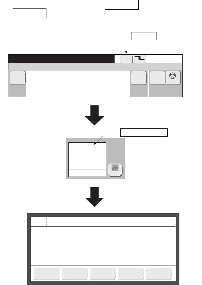
Message name[ ]
[Ready ]Print description
Ink Low Warning
The ink level in the ink reservoir is low.
Cause 1. The ink reservoir is almost empty.
2. The Low Level sensor in the ink reservoir is faulty.
Solution 1. Add more ink to the ink reservoir within 60 minutes.
2. Check the Low Level sensor.
Ink Low Warning
Makeup Low Warning
Current user ID : user2
(3) When there is a “Not reset alarm”, a Warning is displayed.
When the Warning is pressed, a warning list is displayed.
Press Warning .
Warning list
Press Ink Low Warning .

●Basic operation 3-22
Excitation V-ref.
Ref. ambient temperature
Automatic update
Incremental change
Print trigger source
Print data
Inc.
Excitation V update [Standby ]
SensorButton input
Data to be displayed
For test
Incre-
ment
Enter
Clear
Decre-
ment
3.3.3 Basic operation to change the settings
(1) Overview
●There are 3 types of settings.
No. Classification
Set value confirmation
method
Set value change method
1 Setting of value
The value is displayed on
the numeric buttons.
Display the value window by
pressing the numeric button
and input the value.
2
Setting with few selections.
(All selection buttons are
displayed: mainly a choice
between the two)
The pressed button
becomes yellow.
Press the applicable button.
3
Settings with many selections.
(When a button is pressed, a
selection menu is displayed in a
window.)
The set value is displayed
on the input button.
Display the selection menu
window by pressing the but-
ton and select the
relevant item.
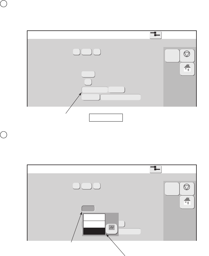
(2) Operation (Maintenance “Excitation V update” screen is used as an
example.)
●There are 3 types of settings.
1
“Excitation V-ref.” setting (Value input)
Display the numeric window by pressing the numbers button and input the value.
Minimum value is input.
Each time this button is
pressed, the set value is
increased by 1.
The value window is closed
and the input value is reflected
on the screen.
Each time this button is pressed,
the set value is decreased by 1.
Press the numeric button.
Numeric windows displayed.
Excitation V update [Standby ]
Excitation V-ref.
Ref. ambient temperature
Automatic update
Incremental change
Print trigger source
Print data
Inc.
SensorButton input
Data to be displayed
For test
3-23 ●Basic operation
2
Excitation V-ref.
Ref. ambient temperature
Automatic update
Incremental change
Print trigger source
Print data
Inc.
Data to be displayed
For test
Sensor
Button input
Excitation V update [Standby ]
Excitation V-ref.
Ref. ambient temperature
Automatic update
Incremental change
Print trigger source
Print data
Inc.
Data to be displayed
For test
Sensor
Button input
Disable
Dec.
Inc.
Excitation V update [Standby ]
“Print trigger source” setting
Press the applicable button.
3
“Automatic update” setting
Display the selection menu window by pressing the button and close from within that window.
Press the Button input .
Press the button.
Selection menu window is displayed.

●Basic operation 3-24
Date/time setup
Current time
Calendar time control
Calendar time
Clock system
24-hour clock
clock stop
(year)
(month) (day)
(hour) (minute) (second)
(year)
(month) (day)
(hour) (minute) (second)
12-hour clock
Press OK to apply the date/time setup.
The current time affects the clock display only
when changes are made.
Calendar character will be printed based on "calendar time"
same as current time
[Ready ]
No. Classification Contents
1
Screens with OK
and Cancel
● When OK is pressed, the set contents are accepted
and the display returns to the previous screen.
● When Cancel is pressed, the set contents are canceled
and the display returns to the previous screen.
● Apply is not displayed.
2 Screens with Back
● When Back is pressed, the display returns to the
previous screen.
● When Apply is pressed, the set contents are accepted.
● When Back was pressed in the state in which
Apply is not pressed, a confirmation window is displayed
and action is requested.
(2) Screen examples
Screen with OK and Cancel
[Example of Date/time setup screen]
3.3.4 Operations (OK, Back, Apply) which exit from a screen
(1) Overview
●There are 2 types of setup screens.
● When “Apply” was performed during editing of the current message and at the User environment
setup screen, the set contents are reflected in printing.
● For the setup of whether or not to show some buttons as icon, refer to "6.3 setup the touch screen."
1
Cancel
OK
When set without
icons at the Touch
screen setup screen.
3-25 ●Basic operation
Save message [Ready ]
Message name [ ]
Save message as (name)
Group No.
Free space 20%
Print format [Ready ]
Select line
Bold times 1- 9
Bar code
Message name [ ]
Inter-char. space
(MAX 27 )
Line
spacing
(MAX 2 )
Dot matrix
[Example of Save message screen]
Screen with Back button
[Example of Print format screen]
2
Cancel
OK
Apply
Back
When set without
icons at the Touch
screen setup screen.

●Basic operation 3-26
Print format
Ready
Message name
Data Entry Confirmation
The data entered will be used in the print message.
Solution 1. To save the input data and use it for print message, press <OK>.
2. To delete the input data, press <Cancel changes>.
3. To return to the previous screen, press <Cancel>.
[Example of confirmation message when Back was pressed]
Accepts the
set contents.
Return from set
contents to original
contents.
Closes the message window with the
set contents remaining displayed.

4-1 ●Print description screen
4.
CREATION AND PRINTING OF MESSAGES
Print description [Stop ]
Ink operating time (hours)
Cumulative op. time (hours)
Print count (prints)
Ink pressure (MPa standard value: )
Message name[ ] Current user ID : user2
4.1 Print description screen (initial screen)
(1) Overview
● The display is shifted to the screens for message edit and Maintenance, Auxiliary function, and
Environment setup menu screens by pressing each button.
● The print image can be confirmed at the “Print layout” area.
Item Description Reference
Change message ● Edits and corrects current message. 4.2
Select message ● Calls and prints saved messages. 4.3
Overwrite message ● Overwrites the current message. 4.4
Adjust print parameters ● Creates and edits messages different from the current message. 4.14.4
Operation management ● Displays operation status. 5.2
Maintenance ● Displays the maintenance menu. 5
Auxiliary function ● Displays the auxiliary functions menu. 7
Environment setup menu ● Displays the environment setup menu 6
Select login user ● Logs in again as a different user from currently logged in user. 6.4
Create/Edit message ● Creates and edits messages different from the current message. 4.5
Print count reset ● Reset the print count to zero (0). 4.1
The Shutdown is displayed
during ink ejection.
The Startup is displayed
during stop.
Displays the
print layout.
Displays the operation
management
information.
When the Menu is pressed,
the display is switched.
Displays the zoom in
or zoom out.
Displays the scroll.
For details
regarding the
printing method
display, refer to
"4.14.1 Set the
character
height,
character width,
and
orientation."
Print count is
reset to 0.
If is indicated in
off-line state.

●Print description screen 4-2
Print description [Stop ]
Ink operating time (hours)
Cumulative op. time (hours)
Print count (prints)
Ink pressure (MPa standard value: )
Message name[ ] Current user ID : user2
(3) Current message and saved message
● There are 2 types of messages; current messages and saved messages.
Types of messages
Type Features
Current message
● The message currently being printed is called “current message”.
● When the power is turned on, the last current message is memorized.
● The print layout of the current message is displayed on the Print description
screen.
● The contents of the current message can be changed by calling the message
from the saved messages.
Saved message
● Messages can be given a message name. Multiple messages can be saved
beforehand.
(2) Operation
The Print description screen is displayed.
Press the Print count reset on the Print description screen.
Confirmation message of "Print count reset." will be displayed.
1
Press OK on the confirmation message window.
Print count will be reset to zero (0).
2
Print count reset

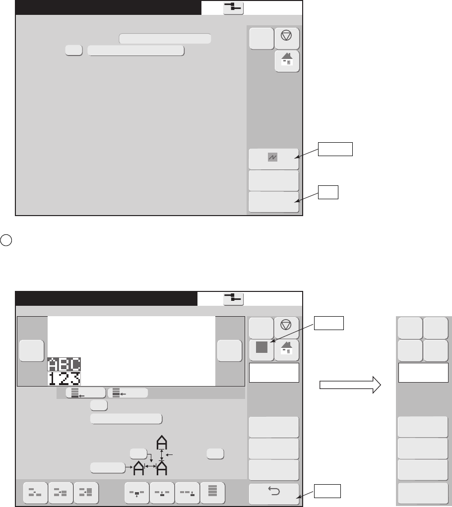
4-3 ●Edit messages to be printed
4.2 Edit messages to be printed (Change message screen)
(1) Overview
● Edits the current message (message currently being printed).
● There are 2 types of print format.
● Style displayed in the Details mode of the message name list display of the Select message screen shows the
type of print format.
Types of Style
Type of Style Meaning Features
(a) Individual Individual setup of fixed layout Multiple character sizes can be mixed.
(b) Overall Overall setup of fixed layout
Character size and inter-character space set
value are matched at all lines.
Only 1 column can be input.
(c) Free layout Setup of free layout
An arbitrary position can be set for each print
item.
● The background of the current message edit screen is colored.
Edit screen background color
Editing objective Background color
Current message Light green
Saved message Gray
Print items are stacked
from the bottom.
Columns (vertical list) with the same
line count, line spacing, and character
size list are linked and handled.
Columns of several different
formats can be input.
(a) Individual setup
(b) Overall setup
Print items are stacked
from the bottom.
Only one column (vertical list) with the same line count,
line spacing, and character size list is handled.
(c)
Free layout
An arbitrary position can be
set for each print item.
A print item can be lapped over
other print items.

●Edit messages to be printed 4-4
●When the Apply is pressed during editing, the input value is applied and reflected in printing.
The input value is also applied when returning to the Print description screen by pressing the Back .
●When the Back is pressed at the Print format, Print specifications, and Edit message, various print setup
screens, the confirmation message "Data Entry Confirmation" is displayed.
Functions of confirmation message “Data Entry Confirmation”
Button Contents
OK Applies the message by input value and switches to the Print description screen.
Cancel changes Cancels the input value and returns to the state before the change.
Cancel Returns to the original screen with the input data as it was.

4-5 ●Edit messages to be printed
Print description [Stop ]
Ink operating time (hours)
Cumulative op. time (hours)
Print count (prints)
Ink pressure (MPa standard value: )
Message name[ ] Current user ID : user2
Change message [Stop ]
Message name[ ]
:Multiple print formats can be mixed.
<Format Setup>
:Character size and inter-character space set
value are matched at all lines.
Only 1 column can be input.
:An arbitrary position can be set for each print
item.
Change the display contents using the group, search, sort, and select page
functions so that the desired message name is displayed.
3
(2) Operation
The Print description screen is shown below.
Press the Change message on the Print description screen.
The Print format screen is displayed.
1
Press the Back .
To save as a registered print data ,press save and back .
4
Press Individual setup , Overall setup or Free layout to modify <Format
setup>.
2
Change message

●Call and print saved messages 4-6
4.3 Call and print saved messages
(1) Overview
● Calls and prints saved messages.
● The message currently being printed is called "Current message".
● When a message is called during printing, the Print description display changes to the called message and
printing continues to print the previous contents. The printed result changes from the next printing.
● The desired message can be efficiently found by changing the display contents of the message name list.
● A print image of the registered print data can be checked. (RX2-S only)
Method of changing the message name list display
Item Contents
Group
● Press the group No. button.
● Only the messages belonging to the selected group are displayed.
● When "0:All message names" is selected, the message names of all
the groups are displayed.
Previous display, next display ● Switches the message name list display screen.
Select page ● Selects the message name list page.
Sort
● The sort order can be switched by pressing the heading part of the
message name list display.
Search
● The first several characters of a message name are input and only the
message names beginning with those characters are displayed.
● If the Search conditions are not input, all the message names in that
group are displayed.
Display All
● Defines Group No. as "00" and the search condition as space, then
displays message name list.
Details
● Details displays the update date/time, Style, and group No., as well
as the No. and message name.
● Simple list displays the No. and message name.
Free number
● By pressing Free number , all the registered numbers will be
displayed.
● Nicknames will be sorted and displayed in ascending sequence of
Registration numbers.
● Search by Group No. or Search condition input or Display all is
NOT available.
Preview (RX2-S only)
● A print image of the registered print data can be checked by
Preview .
● The print contents currently being printed are not affected.
● Style displayed in the Details mode shows the type of print format.
Types of Style
Type of style Meaning
Individual Individual setup of fixed layout.
Overall Overall setup of fixed layout
Free Set up of free layout.

4-7 ●Call and print saved messages
Select message [Stop ]
Message name[ ]
Group No.
Group name
[ ]
Search condition
No
Message name
No
Message name
Select message [Stop ]
Message name[ ]
Group No.
Group name
[ ]
Search condition
No
Message name
2015.06.01 12:00
2015.06.02 12:00
2015.06.03 12:00
2015.06.04 12:00
2015.06.05 12:00
2015.06.06 12:00
2015.06.07 12:00
2015.06.08 12:00
2015.06.09 12:00
2015.06.10 12:00
OVERALL
OVERALL
OVERALL
INDIV.
INDIV.
INDIV.
INDIV.
INDIV.
FREE
FREE
1
1
1
3
3
5
5
5
5
5
Update Date/Time Style GrNo
Select message [Stop ]
Message name[ ]
Group No.
Group name
[ ]
Search condition
No Message name No Message name
(2) Operation
Press the Select message on the Print description screen.
The Select message screen is displayed.
● Only the RX2-S displays a preview. (Preview is not displayed on the following screens.)
1
Example of Details screen
Search conditions
input
Group
Sort
Previous display ,
Next display
Select page
Display All
OK
Details , Simple list
Free number
By pressing Free number , the screen shown below will be displayed.
Preview

●Overwrite messages to be printed 4-8
Change the display contents using Group, Search, Sort, Select page function,
Display All, so that the desired message name is displayed.
2
Select the message name and press the OK .
The selected message is called and the display returns to the Print description screen.
3
Print description [Stop ]
Ink operating time (hours)
Cumulative op. time (hours)
Print count (prints)
Ink pressure (MPa standard value: )
Message name Current user ID : user2
4.4 Overwrite messages to be printed
(1) Overview
● Overwrites the current message by the same name.
● If the message is saved using the overwrite message function when updating the count value, the same
print description can be selected later.
● Message name cannot be changed.
See “4.6 Save created messages” for message save.
(2) Operation
The Print description screen is displayed.
Press Overwrite message .
“Same Print Data Found” message is displayed.
1
Press Enter .
Save is performed.
2
Overwrite message

4-9 ●Edit messages different from the current message
1
4.5 Edit messages different from the current message
(1) Overview
● Edits and saves a specific saved message or a new message.
● Since a message different from the current message (message currently being printed) is edited, the
contents currently being printed are not affected.
●When the Back button is pressed at the Edit message screen or other edit screen, the display returns to the
Select message screen. Before pressing the Back button, always save the created and edited message.
If returned to the Select message screen without saving the message, the edited message is lost.
● The desired message can be efficiently found by changing the display contents of the message name list.
● A print image of the registered print data can be checked. (RX2-S only)
Method of changing the message name list display
Item Contents
Group
● Press the group No. button.
● Only the messages belonging to the selected group are displayed.
● When "0:All message names" is selected, the message names of all
the groups are displayed.
Previous display, next display ● Switches the message name list display screen.
Select page ● Selects the message name list page.
Sort
● The sort order can be switched by pressing the heading part of the
message name list display.
Search
● The first several characters of a message name are input and only the
message names beginning with those characters are displayed.
● If the Search conditions are not input, all the message names in that
group are displayed.
Display All
● Defines Group No. as "00" and the search condition as space, then
displays message name list.
Details
● Details displays the update date/time, Style, and group No., as well
as the No. and message name.
● Simple list displays the No. and message name.
Free number
● By pressing Free number , all the registered numbers will be
displayed.
● Nicknames will be sorted and displayed in ascending sequence of
Registration numbers.
● Search by Group No. or Search condition input or Display all is
NOT available.
Preview (RX2-S only)
● A print image of the registered print data can be checked by
Preview .
● The print contents currently being printed are not affected.
● Style displayed in the Details mode shows the type of print format.
Types of Style
Type of style Meaning
Individual Individual setup of fixed layout.
Overall Overall setup of fixed layout
Free Set up of free layout.

●Edit messages different from the current message 4-10
1
Create/Edit message [Stop ]
Message name[ ]
Group No.
Group name
[ ]
Search condition
No
Message name
No
Message name
Change the display contents using Group, Search, Sort, Select page function,
Display All, so that the desired message name is displayed.
2
Select the message name and press the OK .
To create a new message, press the Create new message .
The change message screen is displayed.
3
(2) Operation
Press the Create/Edit message on the Print description screen.
The Create/Edit message screen is displayed.
1
Search conditions
input
Group No.
Sort
Previous display ,
Next display
Select page
Display All
OK
Details , Simple list
Free number
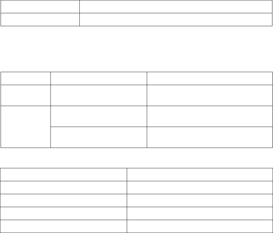
4-11 ●Save created messages
4.6 Save created messages
(1) Overview
● Saves created messages.
● A save No. is automatically assigned.
● The same message name cannot be assigned.
● Saving to a selected group is possible.
● Free spaces are displayed.
Item Contents
Free space Proportional of save area which is vacant.
● If the number of input characters is small, the capacity necessary to save the message decreases. A lot of
small capacity messages can be saved. When there are many large capacity messages, the number of
messages which can be saved decreases.
Maximum message save count
Model type Maximum save count Remarks
RX2-B 24 messages
24 messages can be saved without regard to
their capacity.
RX2-S
300 messages
300 messages can be saved without regard
to their capacity.
Option :
Up to 2,000 messages
The save count depends on the capacity.
*1) Maximum message save count
Conditions example Message save count
Characters 70 chars 2,000 messages
Characters 20 chars, calendar 1, count 1 Approx. 1,900 messages
Characters 240 chars Approx. 800 messages
Characters 240 chars, calendar 8, count 8 Approx. 300 messages
*1)

●Save created messages 4-12
Change message [Stop ]
Message name[ ]
:Multiple print formats can be mixed.
<Format Setup>
:Character size and inter-character space set
value are matched at all lines.
Only 1 column can be input.
:An arbitrary position can be set for each print
item.
Save message [Stop ]
Message name [ ]
Save message as (name)
Group No.
Free space 20%
(2) Operation
The Change message screen is displayed.
Press the Save and Back .
The Save message screen is displayed.
1
Save and Back
OK

4-13 ●Save created messages
Input the message name and press the Enter .
A keyboard is displayed.
Press Message name.
A keyboard is displayed.
Save message [Stop ]
Message name[ ]
Save message as (name)
Group No.
Free space 20 %
2
3
Press the OK .
The message is saved.
4
Enter

●Set the print format (Fixed layout) 4-14
4.7 Set the print format(Fixed layout)
4.7.1 Select the print items to be edited
(1) Selecting one print item
● Sets and changes the print format including the character size for the print item to be edited.
● There are 3 methods of selecting the print item to be edited.
Print format [Stop ]
Select Line
Bold times 1 9
Bar code
Message name[ ]
none
Dot matrix
Inter-char. space
(MAX 27 )
Line
spacing
(MAX 2 )
Methods of selecting the print item to be edited
Type Features
Directly touching the print item The touched item becomes the editing objective.
Previous column, next column
The topmost line of the previous column or the next column
becomes the editing objective
Select line
The print item of the specified line in the editing objective column
becomes the editing objective.
The editing objective can be changed by
directly touching a print item.
The colored print
item is the editing
objective.
Previous column
The selected line
in the editing
objective column
becomes the
editing objective
by Select line
button.
Next column
Next column
First line Second line First line Second line
Previous
column
How to change the print item to be edited

4-15 ●Set the print format (Fixed layout)
Print format [Stop ]
Bold times 1 9
Bar code
Message name[ ]
none
Dot matrix
Inter-char. space
(MAX 27 )
Line
spacing
(MAX 2 )
(2) Selecting all print items
● All the print items become the editing objective.
● When placed into the Overall mode, first matching to the format information of the 1st line is
performed.
● Overall mode is cancelled after closing the Change message screen.
To Overall
One print item becomes
the editing objective.
All the print items become
the editing objective.
Overall
Overall (To cancel)
How to change the print item to be edited
*In case of RX2-HD6

●Set the print format (Fixed layout) 4-16
Print format [Stop ]
Select Line
Bold times 1 9
Bar code
Message name[ ]
none
Dot matrix
Inter-char. space
(MAX 27 )
Line
spacing
(MAX 2 )
4.7.2 Set the number of print lines
(1) Function
● Sets the number of lines of the selected column.
● The number of lines which can be set is "1 to 5".
Maximum line count
Model type Maximum line count
RX2-B 3 lines
RX2-S
3 lines
(Option : Up to 5 lines)
● When the number of vertical dots exceeds the maximum number of dots, the characters size
becomes 5×8(5×7).
The colored print
item is the editing
objective.
1 line
2 lines
1 line
2 lines
Example for changing the number of lines of the editing objective column
3 lines
*(Option : Up to 5 lines)

4-17 ●Set the print format (Fixed layout)
Print format [Stop ]
Select Line
Bold times 1 9
Bar code
Message name[ ]
none
Dot matrix
Inter-char. space
(MAX 27 )
Line
spacing
(MAX 2 )
4.7.3 Add and delete print items
(1) Function
● Deletes, inserts, and adds print items in column units.
Methods of adding and deleting print items
Type Features
Delete column Deletes all the print items of the editing objective column.
Insert column Adds a column directly before the editing objective column.
Add column Adds a column at the end.
The colored column is
the editing objective.
Delete Column
Insert Column
Add Column
Delete
column
Insert
column
Add column
Example of deleting, inserting, and adding print items in column units

●Set the print format (Fixed layout) 4-18
Print format [Stop ]
Select Line
Bold times 1 9
Bar code
Message name[ ]
none
Dot matrix
Inter-char. space
(MAX 27 )
Line
spacing
(MAX 2 )
4.7.4 Set dot matrix, inter-character space, and other parameters
(1) Function
● Sets the line spacing, dot matrix, inter-character space, bold font, and bar code.
Bold
● Sets the character to bold.
● The magnification which can be set is "1 to 9".
Line spacing
● Adjust the spacing with the line above.
● Set for each column.
● Can be set up to a maximum of 4 dots.
1
2
The colored print item
is the editing objective.
Bold
Inter-character space
Dot matrix
Line spacing
Adjustment char. cond.
Model type Maximum line spacing
RX2-B 2 dots
RX2-S 4 dots (5 lines : 0 to 2)

4-19 ●Set the print format (Fixed layout)
Dot matrix
● Sets the character size.
3
Settable sizes (horizontal dots × vertical dots)
4×5, 5×5, 5×8(5×7), 9×8(9×7), 7×10,
10×12, 11×11, 12×16, 18×24, 24×32,
5×3 (chimney), 5×5 (chimney), 7×5(chimney) (RX2-S only)
● See “6.1 Set the user environment” for 5×8, 5×7 and 9×8, 9×7 switching. However, for special charac-
ters, accent characters, Russian characters, Arabic numbers, and Arabic letters, select character size with
vertical 8 dots since the pattern is designed with vertical 8 dots.
● The kinds of characters which can be input are defined for each character size. A space is entered when
there is no corresponding character for the changed character size.
Kinds of characters which can be input by character size
Character kind 4×5 5×5
5×8
(5×7)
9×8
(9×7)
7×10 10×12 11×11 12×16 18×24 24×32
Chimney
5×3
Chimney
5×5
Chimney
7×5
Chinese character XXXXXX XXXX
Kana XX X X XXXX
Alphabet letters,
numeric, symbols
X
Space X
User pattern
Punct. character X XXX
Dedicated character
XX X XXXXX X X X
Accent character XX X XXX
Greek character XX X XXX
Russian character XXX
Arabic numeric X X XXX
Arabic letter XX XX X XXX
● Communication is unsupported for Russian characters of 5×5, 5×5(chimney) and 7×5(chimney).
● Multiple character sizes can be freely combined. However, there is a limit on the total number of vertical
dots.
Total vertical dots limit
RX2-B RX2-S
Total vertical dots 30 dots
30 dots
(Option : Up to 32 dots)
Character sizes having 8 or less vertical dots are calculated as 8 dots.
● Chimney characters consist of characters which can be written vertically.
Line direction
Chimney printing example

●Set the print format (Fixed layout) 4-20
Inter-character space
●Sets the spacing between character and character.
4
● For user pattern (user pattern), patterns can be designed at the inter-character space part.
● For special characters also, a pattern can be designed at the inter-character space. Set an inter-character
space the same as the values shown in the table below.
Inter-character space minimum set value
Character kind 5×5
5×8
(5×7)
9×8
(9×7)
7×10 10×12 11×11 12×16 18×24 24×32
Chinese character - - - - - 0 4 6 -
Kana -0-02-46-
Dedicated character - 1 - 1 - - - - -
Arabic numeric 02000-222
Arabic letter - 2 - - 0 - 2 2 2
English A English B
Vertical 8 dots
Horizontal 5 dots Inter-character space
Character size: 5
×8
Inter-character space: 2 dots
Relationship between character and inter-character space
User pattern (save character)
English A
Vertical 8 dots
Horizontal 5 dots Inter-character space
Character size: 5
×8
Inter-character space: 5 dots
Relationship between user pattern and inter-character space

4-21 ●Set the print format (Fixed layout)
Adjust Inter-character space [Stop ]
Select line
Message name[ ]
Select area
Inter-char. space
Adjust Inter-character space
OK
Start End
Cancel
Set value [ ]
Character size inter-character space
Character size
(horizontal × vertical)
Number of horizontal
dots of character
Inter-character space
which can be input by
user pattern creation
Maximum inter-character
size which can be set
4×5 4 4 28
5×5 5 3 27
5×8(5×7) 5 3 27
9×8(9×7) 9 7 23
7×10 7 1 25
10×12 10 6 22
11×11 11 5 21
12×16 12 4 20
18×24 18 6 14
24×32 24 8 8
5×3 chimney 5 0 27
5×5 chimney 5 0 27
7×5 chimney 7 0 25
1
2
●Inter-character space can be set in character units using the Adjustment char. cond. .
●Select the character column where the inter-character space will be set using Start and End , input the
inter-character space set value, and press the OK .
Chimney is available on RX2-S as option.
Inter-char. space
Start
End
OK
Back
● When the inter-character space of the print format screen changed, the value set in character units
changes to the same value.
● The display value of the inter-character space of the print format screen displays the inter-character
space of the first character.

●Set the print format (Fixed layout) 4-22
4.7.5 Print a bar code (RX2-S only)
(1) Kinds of bar codes
● Different kinds of bar codes can be set for each print item.
Kinds of bar codes
Bar code Kinds of characters which can be input Remarks
Code 39
0 to 9 A to Z Space
+ - (minus) / . (period) $ %
ITF 0 to 99 Input of two-digit numbers
NW-7
0 to 9
+ - (minus) / . (period) : (colon) $
EAN-13 0 to 9
EAN-13 Add-On 5 0 to 9
EAN-8 0 to 9
UPC-A 0 to 9
UPC-E 0 to 9
Code 128
(code set B)
0 to 9 A to Z a to z Space
FNC1 Code B Code C Symbols
Input numeric of two-digit
numbers
Code 128
(code set C)
0 to 9 FNC1 Code B Code C
Data matrix
(DM)
0 to 9 A to Z a to z Space
FNC1 Symbols
QR code, Micro QR Same as above.
DotCode Same as above.
GS1 DataBar 0 to 9
Limited, Omnidirectional and
Stacked
● When a bar code of the same kind was set at adjacent print items, only the continuous series bar code is
assumed. However, fixed length bar codes such as EAN-13, EAN-8, UPC-A, UPC-E,
EAN-13 Add-On 5 and GS1 DataBar become independent bar codes.
● For multiple settings, provide a print item for which a bar code is not set between the print items with a
bar code set.
● Up to a maximum of 4 DM (Data Matrix), code 128, QR code, Micro QR and GS1 DataBar can be set
respectively.
QR code and Micro QR can be collectively set up to 4.
● DotCode can be set up to 2.
● Since the number of horizontal dots is uniquely determined for bar codes, an inter-character space cannot
be set.
● When DM(16×16) is selected and when Bold is set to 2, IJ printer can print Cell size (width and height)
of 2 dots.
● A bar code can be set even for print items with a calendar and count set. However, when calendar
substitution, zero suppression, or an invalid character is set, for the bar code setting, the relevant character
is deleted.
● Neither the calendar nor the count set can be set to the country code.
● When code set C of code 128 was set when the English alphabet is set for the count upper limit, the
relevant character is deleted.
● Since start and stop codes are automatically generated, input as print description is unnecessary.
● A barcode with the identification numbers can be set in 1 line or 2 lines setting.
When in 2 lines setting, the barcode with the identification numbers can only be set to either upper or
lower line.
If the barcode is set to the upper line, it cannot be set to the lower line or vice versa.
● For GS1 DataBar, neither the calendar nor the count can be set to 1st, 2nd and 3rd digit.
● For ITF, the wide bar and space width can be set to horizontal 2 dots or 3 dots.
See the Technical Manual "9. APPENDIX" for details.

4-23 ●Set the print format (Fixed layout)
Print format [Stop ]
Select Line
Bold times 1 9
Bar code
EAN readable code
Message name[ ]
EAN-13
Dot matrix
Inter-char. space
(MAX 0 )
Line
spacing
(MAX 0 )
EAN Prefix
Print format [Stop ]
Select Line
Bold times 1 9
Bar code
Max digits numeric: 24 ,alphameric: 12- 23
Message name[ ]
DM(16x16)
Dot matrix
Inter-char. space
(MAX 4 )
Line
spacing
(MAX 0 )
Print format [Stop ]
Select Line
Bold times 1 9
Bar code
Message name[ ]
ITF
Dot matrix
Inter-char. space
(MAX 0 )
Line
spacing
(MAX 0 )
Wide bar/space width
(2) Examples
Example of EAN-13
Example of Data Matrix
1
2
Sets barcode type.
Sets "Disable" or
character size of
identification code
when EAN-13,
EAN-8, UPC-A,
UPC-E, EAN-13
Add-On 5 or GS1
DataBar is
selected.
(When character
size is 12 x 16 or
larger.)
Sets an EAN Prefix
code when EAN-13,
EAN-8 or EAN-13
Add-On 5 is selected
(the EAN Prefix code
can also be set at the
Edit message screen
(See "4.14.3 Set
various printing".)).
Sets barcode type.
Displays maximum
input digits for DM
(Data Matrix)
Selectable matrix
size depends
on the character
size.
Example of ITF
3
Sets barcode type.
Sets the wide bar/
space width when
ITF is selected.

●Set the print format (Free layout; RX2-S only) 4-24
Bold times 1 9
Bar code
none
Inter-char. space
(MAX 0)
Dot matrix
Print format [Stop ]
Message name[ ]
4.8 Set the print format (Free layout; RX2-S only)
4.8.1 Select the print items to be edited
● Set and change the print format including the character size for the print item to be edited.
● There are 2 methods of selecting the print item to be edited.
Methods of selecting the print item to be edited
Type Features
Directly touching the print item The touched item becomes the editing objective.
Previous item, next item The previous item or the next item becomes the editing objective.
The editing objective can be changed by
directly touching a print item.
The colored print
Item is the editing
objective.
Previous item
Next item
Display the vertical
printing range and
horizontal printing
range.

4-25 ●Set the print format (Free layout; RX2-S only)
Print format [Stop ]
Message name[ ]
Bold times 1 9
Bar code
none
Inter-char. space
(MAX 0)
Dot matrix
4.8.2 Set the print items to be edited
(1) Function
● Set the "horizontal (X) coordinate" and "vertical (Y) coordinate" of the selected item at the
bottom-left.
● The total number of vertical dots and limit of the coordinate are as follows;
Total vertical dots and limit of coordinate
Model type
Total vertical dots Horizontal (X)
coordinate
Vertical (Y) coordinate
RX2-S
30 dots
(Option : Up to 32 dots)
0 to 31999
0 to 29
(Option : Up to 31)
Horizontal (X) coord. = 0
Vertical (Y) coord. = 0
Horizontal (X) coord. = 42
Vertical (Y) coord. = 4
Display the upper limit line of the
vertical dots.
(The line position is changed by the
display magnification)
Display the Horizontal (X)
coordinate
Display the lower limit
line of the vertical dots.
(The line position is
changed by the
display magnification)

●Set the print format (Free layout; RX2-S only) 4-26
Print format [Stop ]
Message name[ ]
Bold times 1 9
Bar code
none
Inter-char. space
(MAX 0)
Dot matrix
Item position select
Item move with button or touch on screen.
Horizontal (X)
Vertical (Y)
(2) Set the coordinate of one print item
● Set and change the "horizontal (X) coordinate" and "vertical (Y) coordinate" of the print item to be
edited, at the bottom-left.
● Press Individual item move, and set the coordinate of the print item to be edited.
● There are 3 methods of setting the horizontal (X) coordinate and vertical (Y) coordinate.
● The horizontal (X) coordinate and vertical (Y) coordinate cannot be set over the range of [ Table of
(1) ].
Methods of setting the horizontal (X) coordinate and vertical (Y) coordinate
Type Features
Directly touching the screen
The print item to be edited can be moved by directly touching the
screen within the limit of vertical dots.
Set the value of the coordinate
The print item to be edited can be moved by setting the value of
the "horizontal (X) coordinate" and "vertical (Y) coordinate" on
the screen.
Set the position by cursor button
The print item to be edited can be moved dot by dot one by means
of ↑ ↓ ← → buttons.
The editing objective can be moved by
directly touching the screen.
Cursor button
Press the Cancel if canceling the
moving the coord..
Individual item move
Press the OK if the print item
has been moved.
The horizontal (X)
coordinate and
vertical (Y) coordinate
of editing objective can
be moved by directly
touching the screen.
4-27 ●Set the print format (Free layout; RX2-S only)
Print format [Stop ]
Message name[ ]
Bold times 1 9
Bar code
none
Inter-char. space
(MAX 0)
Dot matrix
tem position select
Item move with button.
(3) Set the coordinate of all print items
● All print items can be moved collectively.
● Press Overall item move , and move all items.
● All print items can be moved dot by dot by means of ↑ ↓ ← → buttons.
● The horizontal (X) coordinate and vertical (Y) coordinate cannot be set over the range of Table of
item (1).
Cursor button
Press the Cancel if canceling the
moving the coord..
Overall item move
Press the OK if the print
item has been moved..

●Set the print format (Free layout; RX2-S only) 4-28
Print format [Stop ]
Message name[ ]
Bold times 1 9
Bar code
none
Inter-char. space
(MAX 0)
Dot matrix
Item position select
Touch on screen at insert position.
The touch position is left-bottom coordinate of item.
4.8.3 Add and delete print items
(1) Function
● Add or delete print items one by one.
Methods of adding and deleting print items
Type Features
Insert item Add the print item at the selected position.
Delete item Delete the print item to be edited
A print item can be created by directly
touching the print layout screen.
● Press Insert item and touch the print layout screen, then the print item (character size is 5×7
or 5×8) will be created.
When the print item is created, if the horizontal (X) coordinate or vertical (Y) coordinate is over
the limit of range of the coordinate, the horizontal (X) coordinate or vertical (Y) coordinate will
be adjusted automatically.
● When there is only one print item, if Delete item is pressed and the print item is deleted, a
print item (character size is 5×7 or 5×8) will be created at the horizontal (X) coordinate = 0,
vertical (Y) coordinate =0.
Insert item

4-29 ●Set the print format (Free layout; RX2-S only)
Print format [Stop ]
Message name[ ]
Bold times 1 9
Bar code
none
Inter-char. space
(MAX 0)
Dot matrix
Item position select
Item move with button or touch on screen.
Horizontal (X)
Vertical (Y)
A print item (character size is 5×7 or 5×8) will be created.
The method of setting the horizontal (X) coordinate and
vertical (Y) coordinate is as same as "Individual item move".

●Set the print format (Free layout; RX2-S only) 4-30
4.8.4 Set dot matrix, inter-character space, and other parameters
● Set the dot matrix, inter-character space, bold font, and bar code.
● The methods of setting is the same as fixed layout. See "4.7.4 Set dot matrix, inter-character space,
and other parameters" for details.
● The bottom-left coordinate of the selected print item is first fixed and adjust as follows:.
When changing the dot matrix, inter-character space, etc…, the top-right coordinate of the print
item can be over the limit of coordinate.
Should the top-right of the print item go beyond the limit of horizontal (X) coordinate, it will be
automatically adjusted to horizontal (X) coordinate =31999.
Should the top-right of the print item go beyond limit of vertical (Y) coordinate, it will be
automatically adjusted to vertical (Y) coordinate = 29 (3 lines upgrade) or 31 (4 lines or 5 lines
upgrade).
Char. size : 12×16
Bold font :
×1
Char. size : 12
×16
Bold font :
×2
Horizontal (X) coordinate = 31961 Horizontal (X) coordinate = 31922
Horizontal (X) coordinate = 31999
Char. size :
12
×16
Char. size :
18
×24
Vertical (Y) coordinate=31
Vertical (Y) coordinate=8
Vertical (Y) coordinate=16

4-31 ●Set the print format (Free layout; RX2-S only)
4.8.5 Print a bar code
● Set bar code for free layout.
● Basic method of the setting bar code is the same as the method for the fixed layout. See the "4.7.5
Print a bar code" for details.
● There are some restrictions for setting the bar code for free layout. The restrictions are described as
follows;
The restrictions of the setting bar code for free layout
Bar code Restriction
Data Matrix (DM) Up to maximum of 1 DM, per one message.
QR code and Micro QR
QR code and Micro QR can be collectively set up to 1,
per one message.
GS1 DataBar Up to maximum of 1 GS1 DataBar, per one message.
Code 128 Up to maximum of 1 Code 128, per one message.
In case that a bar code of the same
kind was Set at adjacent print items
Two of the bar code are not handled a series of barcode.
Each bar code is handled as an independent bar codes.
Char. size : 12×16
Bar code : none
● When changing the bar code, the top-right coordinate of the print item can go over the limit of
coordinate.
Should the top-right of the print item go beyond the limit of horizontal (X) coordinate, it will be
automatically adjusted to horizontal (X) coordinate=31999.
Char. size : 12×16
Bar code : Code39
Horizontal (X) coordinate = 31961
Horizontal (X) coordinate = 31920
horizontal (X) coordinate = 31999
4.8.6 Cautions for printing overlapped some print items
● If multiple numbers of print items are overlapped, the printing may be aborted depending on the
number of print items or characters because it requires time to create the print data while printing is
in process.
In this case, the alarm "Free Layout Printing Disabled" occurs.
● Please first conduct print test at the free layout setting, and if the alarm "Free Layout Printing
Disabled" occurs, delete some print items which are overlapped, or decrease the value of ink drop
use setting.

●Print characters 4-32
4.9 Print characters
Ex. Dedicated character (Simple Chinese)
Lines and Message length (Characters)
Model type 1 line 2 lines 3 lines
RX2-B 60 char. × 1 line 30 char. × 2 lines 20 char. × 3 lines
RX2-S 240 char. × 1 line 120 char. × 2 lines 80 char. × 3 lines
*) RX2-S OP : Up to 5 lines
OP : Up to 1,000 characters
4.9.1 Print fixed characters
(1) Function
● Inputs the characters to be printed.
● The kinds of characters which can be input are defined for each character size. Moreover, there is an
appropriate inter-character space depending on the kind of character. (See "4.7.4 Set dot matrix,
inter-character space, and other parameters".)
● There is an "Insert" mode and an "Overwrite" mode when inputting.
● "Duplicate" by selecting the start and end of the character string and "Paste" at an arbitrary position are
possible.
● The characters which can be set as dedicated characters are shown below.
For dedicated characters, single words are handled collectively at input and deletion.
● Inputting an Arabic character will move the cursor to the left.
● Use the Insert mode to input Arabic characters.
● There are no limits on the number of digits which can be input at one print item.

4-33 ●Print characters
Edit message [Stop ]
Message name[ ]
(2) Operation
The Edit message screen is displayed. (See "3.3.1 Operating Scheme".)
Touch the print item which is to be the objective of message editing.
Prev. Item and Next Item may also be pressed.
The print description of the selected print item is displayed at the print description edit area.
1
Touch the position at which input in the print description edit area is to begin
and move the cursor.
The cursor button may also be pressed.
The cursor is displayed at the selected position.
2
Press the input mode button.
The kind of keyboard is changed.
3
Input the characters and press the Apply .
The character string of the print contents edit area is displayed at the print layout.
4
Print contents edit area
Print layout
Previous item
Cursor
Scroll in the print
description edit area
Input mode button
group
Numeric, Symbols
Alphabet letters Logo (Fixed, Free size)
Punct. character,
Accent character, etc.
Print item No.
Apply
Next item
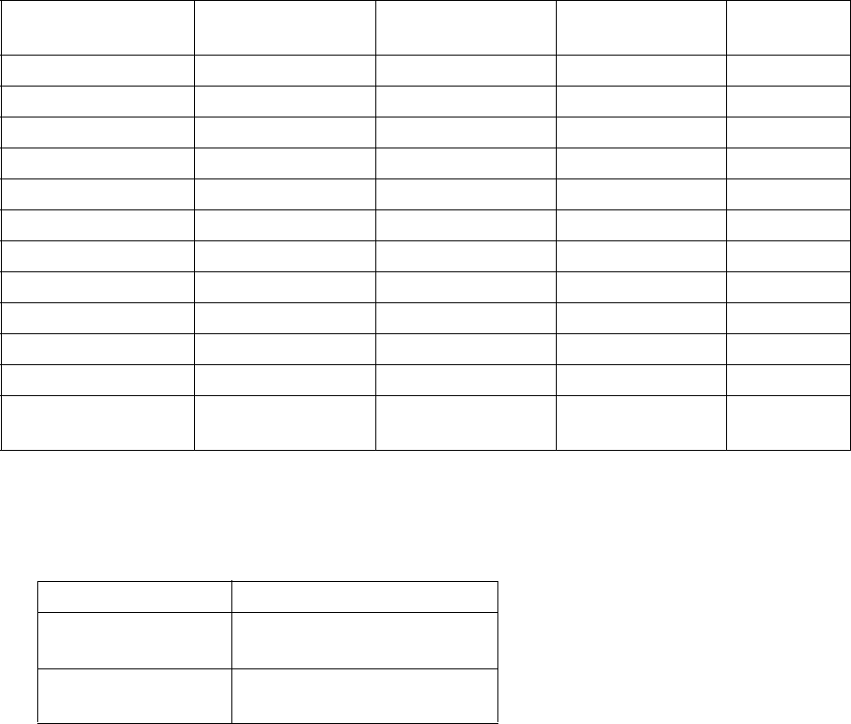
●Use the calendar function 4-34
4.10 Use the calendar function
4.10.1 Print calendar characters
(1) Calendar characters
● When set as calendar characters, the year, month, day, hour, minute, and second are matched to the current
date/time and printed each time the calendar time is changed.
● When "clock stop" is selected for calendar time control at the Date/time setup screen, the inputted
calendar time is referenced and printed.
Kinds of calendar characters
Item
Displays in
"Print layout area"
Number of digits
which can be input
Substitution rules Reference
Year Y 4 Yes
Month M 3 Yes
Day D 3 Yes
Hour h 2 Yes
Minute m 2 Yes
Second s 2 -
Total number of days T 3 - 4.10.1(2)
Week No. W 3 Yes 4.10.1(4)
Day of week 7 3 Yes 4.10.1(5)
Shift code (*1) E 10 - 4.11
Time count (*1) F 3 - 4.12
JAN, FEB, ----
(Month 3 digits)
- 3 - 4.10.1(3)
● A group of calendar characters is called "Calendar block".
(*1) Optional on RX2-S
Maximum Calendar block count
Model type Maximum Calendar count
RX2-B 2
RX2-S
3
(Option : Up to 8)
● Calendar conditions are set for each calendar block.
● Calendar characters cannot be input at the same calendar block as shift code characters and time count
characters.
(Maximum digit : 20 digits/Calendar block)

4-35 ●Use the calendar function
(2) Total number of days
● Use when setting up to print the total number of days from the first of January.
● When set as total date character, it is linked to the calendar time and the print description is changed to
match the current total number of days.
● Leap year and ordinary year are shown in the table below.
● There is no zero-suppression function.
Total number of days
1/1 1/2 ---- 2/28 2/29 3/1 ---- 12/31
Ordinary year 1 2 ---- 59 - 60 ---- 365
Leap year 1 2 ---- 59 60 61 ---- 366
(3) Alphabet month 3 digits (JAN, FEB, ----)
● Use when printing the month in alphabet 3 digits representation.
● For printing in other than English, it is defined by the month 3 digits "Substitution rules" screen.
● When month 3 digits are corresponded to new substitution rules, the English representations shown below
are set beforehand.
English representation
JAN FEB MAR APR MAY JUN
JUL AUG SEP OCT NOV DEC
Edit message [Stop ]
Message name[ ]
Calendar block
Calendar block
Calendar block is
displayed in a red
frame.

●Use the calendar function 4-36
(4) Week number
● Use week number when printing the week of the year.
● One week begins on Monday and ends on Sunday.
● The week including January 4 of that year shall be week one. Making the week including the first Thurs-
day of the year week one is also another way of saying it.
● The beginning of a year not included in week one becomes the last week of the previous year.
Example of counting week number of end and beginning of year
Monday Tuesday Wednesday Thursday Friday Saturday Sunday Week No.
December
21 22 23 24 25 26 27 52
28 29 30 31 53
January
12353
45 6 789101
11 12 13 14 15 16 17 2
(5) Day of the week
● Use when representing and printing the day of the week using a 1 digit character.
● One week begins on Monday and ends on Sunday.
● When the calendar characters "Day of week" are input, the numbers 1 to 7 are printed. When printing other
representations, set the appropriate substitution rules.
Calendar “Day of the week” printing example
Monday Tuesday Wednesday Thursday Friday Saturday Sunday
Standard 1234567
Substitution rule set
by inputting 1 digit.
AB C DEFG
Substitution rule set
by inputting 3 digits
MON TUE WED THU FRI SAT SUN

4-37 ●Use the calendar function
Edit message [Stop ]
Message name[ ]
Calendar
/count
Edit message [Stop ]
Message name[ ]
Year
Month
Day Hour
Minu-
te
Seco-
nd
Total
days
Week
num-
ber
Day
of
week
Shift
code
Time
count
Count
Insert
Over-
write
Calendar
/ count
(6) Operation
The Edit message screen is displayed.
Press the Calendar/count .
The display changes to the calendar/count keyboard and the calendar/count edit window is displayed.
1
Calendar/count
Calendar/count
edit window
Calendar/count
keyboard

●Use the calendar function 4-38
Edit message [Stop ]
Message name[ ]
Year
Month
Day Hour
Minu-
te
Seco-
nd
Total
days
Week
num-
ber
Day
of
week
Shift
code
Time
count
Count
Insert
Over-
write
Calendar
/ count
Edit message [Stop ]
Message name[ ]
Input the calendar characters.
The calendar characters are displayed on the calendar/count edit window.
2
Press OK .
The calendar characters are displayed at the print description edit area.
3
OK
Print item to input
Calendar block is
displayed in a red
frame.

4-39 ●Use the calendar function
Edit message [Stop ]
Message name[ ]
Edit message [Stop ]
Message name[ ]
Year
Month
Day Hour
Minu-
te
Seco-
nd
Total
days
Week
num-
ber
Day
of
week
Shift
code
Time
count
Count
Insert
Over-
write
Calendar
/ count
Touch the print item to input.
The character string of the print contents edit area is displayed at the print layout.
4
To input another calendar, move the cursor to the input position and press
Calendar/count .
The display changes to the calendar/count keyboard and the calendar/count edit window is displayed.
5

●Use the calendar function 4-40
Edit message [Stop ]
Message name[ ]
Year
Month
Day Hour
Minu-
te
Seco-
nd
Total
days
Week
num-
ber
Day
of
week
Shift
code
Time
count
Count
Insert
Over-
write
Calendar
/ count
Edit message [Stop ]
Message name[ ]
Input the calendar characters.
The calendar characters are displayed in the calendar/count edit window.
6
Press OK .
The calendar characters are displayed at the print description edit area.
7
Press Apply .
The character string of the print contents edit area is displayed at the print layout.
8
OK
Apply
Calendar block is
displayed in a red
frame.
Calendar character is deleted
per calendar block unit.

4-41 ●Use the calendar function
4.10.2 Print future date (offset)
(1) Offset function
● Sets the date/time by adding the offset value and the date/time of the internal clock.
● The offset values which can be set are shown in the table below.
Offset value setting range
Year 0 to 99
Month 0 to 99
Day 0 to 1999
Hour -23 to 99
Minute -59 to 99
<Example of offset in month units (2012 is a leap year)>
Calendar time
Offset from yesterday From today
Offset value Offset value
1 month 1 month + 1 day 1 month 1 month + 1 day
2015.01.28 2015.02.27 2015.02.28 2015.02.28 2015.03.01
2015.01.29 2015.02.28 2015.02.28 2015.02.28 2015.03.01
2015.01.30 2015.02.28 2015.02.28 2015.02.28 2015.03.01
2015.01.31 2015.02.28 2015.02.28 2015.02.28 2015.03.01
2015.02.01 2015.02.28 2015.03.01 2015.03.01 2015.03.02
2015.02.02 2015.03.01 2015.03.02 2015.03.02 2015.03.03
2015.02.27 2015.03.26 2015.03.27 2015.03.27 2015.03.28
2015.02.28 2015.03.27 2015.03.28 2015.03.28 2015.03.29
2015.03.01 2015.03.31 2015.04.01 2015.04.01 2015.04.02
2016.01.28 2016.02.27 2016.02.28 2016.02.28 2016.02.29
2016.01.29 2016.02.28 2016.02.29 2016.02.29 2016.03.01
2016.01.30 2016.02.29 2016.02.29 2016.02.29 2016.03.01
2016.01.31 2016.02.29 2016.02.29 2016.02.29 2016.03.01
2016.02.01 2016.02.29 2016.03.01 2016.03.01 2016.03.02
2016.02.02 2016.03.01 2016.03.02 2016.03.02 2016.03.03
2016.02.27 2016.03.26 2016.03.27 2016.03.27 2016.03.28
2016.02.28 2016.03.27 2016.03.28 2016.03.28 2016.03.29
2016.02.29 2016.03.28 2016.03.29 2016.03.29 2016.03.30
2016.03.01 2016.03.31 2016.04.01 2016.04.01 2016.04.02
<Example of year offset (2012 is a leap year)>
Calendar time
Offset from yesterday From today
Offset value Offset value
1 year 4 years 1 year 4 years
2016.02.29 2017.02.28 2020.02.28 2017.02.28 2020.02.29
● There are two offset methods for future date calculations that use Month and/or Year variables, "Offset
from yesterday" and "From today".
(See "4.14.3 Set various printing" for "Offset from yesterdayv and "From today" setting switching.)

●Use the calendar function 4-42
Edit message [Stop ]
Message name[ ]
Calendar
/count
Calendar conditions [Stop ]
Message name[ ]
< Offset > < Substitution rules > < Zero-suppression >
Year
Month
Day
Hour
Minute
Disable
1st screen
2nd screen
Substitution rules No.
Disable
Enable
Disable
Enable
Disable
Enable
Calendar blocks:1/2
Disable
Disable
(2) Operation
Set offset of 1 month at the "YY.MM.DD" calendar block.
The Edit message screen is displayed.
Press Cal. Cond. .
The Calendar conditions screen is displayed.
1
Press Previous or Next and change the objective calendar block.
2
Cursor
Calendar conditions
Calendar block No.
Changes the objective
calendar block.
Objective calendar
block is colored.
Offset setting

4-43 ●Use the calendar function
Calendar conditions [Stop ]
Message name[ ]
1st screen
2nd screen
Substitution rules No.
Calendar blocks:1/2
< Offset > < Substitution rules > < Zero-suppression >
Year
Month
Day
Hour
Minute
Disable
Enable
Disable
Enable
Disable
Enable
Disable
Disable
Disable
Input “1” at offset “Month”.
The character string of the print description edit area is displayed at the print layout.
3
Offset 1 month

●Use the calendar function 4-44
4.10.3 Print by substituting a different character for the date
(substitution rule)
(1) Substitution rule function
● Prints the date and time by replacing it with the selected characters.
● One substitution rule No. is selected for one calendar block.
● The substitution rule No. can be used in common for multiple calendar blocks.
Example of zero-suppression (time 2009.01.02 03:04)
Set contents
Print result
Zero-suppression disabled
Enabled
(space)
Enabled
(character justification)
YY.MM.DD 09.01.02 9. 1. 2 9.1.2
HH.MM 03:04 3: 4 3:4
( =space)
Maximum Substitution rule count
Model type Maximum Substitution rule count
RX2-B 48
RX2-S
48
(Option : Up to 99)
● Kana, alphanumeric, and user pattern can be set as substitution characters.
● The substitution character for year is 25 years from the year of the calendar time.
[Note] The substitution character for year omits the substitution character of the previous year each time one
year elapses.
At this time, the substitution character after 25 years becomes a space.
Moreover, when the current time "Year" is returned to the past, the substitution character for that
year becomes a space.
(2) Zero-suppression function
● Prints by substituting a space for "0" in the high-order digit of the calendar characters.
Also deletes the “0” and prints left-justified.

4-45 ●Use the calendar function
Calendar conditions [Stop ]
Message name[ ]
1st screen
2nd screen
Substitution rules No.
Calendar blocks:1/2
< Offset > < Substitution rules > < Zero-suppression >
Year
Month
Day
Hour
Minute
Disable
Disable
Enable
Substitution rules [Stop ]
Hour
(3) Operation
Set the substitution rule for the "Hour" calendar character.
The Edit message screen is displayed.
Press Cal. Cond. .
The Calendar conditions screen is displayed.
1
Press Previous or Next and change the objective calendar block.
2
Set “Hour” substitution rule to “Enable”.
3
Press Substitution rules .
The Substitution rules screen is displayed.
4
Input Hour the substitution rule for “Hour”.
5
Calendar block No.
Changes the
objective
calendar block.
Substitution rules
Objective calendar
block is colored.
Substitution rules
enabled
"Hour" substitution rules

●Print shift code 4-46
4.11 Print shift code (Optional on RX2-S)
(1) Overview
●Divides one day into multiple work shifts and prints a different code for each work shift.
(Example) Example of one day divided into 3 work shifts
No. Range Print result
1 0:30 to 8:14 A1
2 8:15 to 16:44 A2
3 16:45 to 0:29 A3
(See "(2) Operation" for the shift code setup procedure of this example.)
● Shift code character can be set at only one place in one message. Up to a maximum of 10 digits can be
input.
● Shift code rules are set at the Shift code setup screen.
● For work shift, the start time is specified in hour/minute units. Up to a maximum of 48 shifts can be
specified.
● One shift code rule is held for each message. To input the same shift code at another message, use the
"Duplicate" and "Paste" function. Input the shift code rules, memorize them by pressing Duplicate , and
press Paste at the Shift code setup screen of the other message.
● Shift code characters cannot be input at the same calendar block as another calendar.

4-47 ●Print shift code
Edit message [Stop ]
Message name[ ]
Calendar
/count
Edit message [Stop ]
Message name[ ]
Year
Month
Day Hour
Minu-
te
Seco-
nd
Total
days
Week
num-
ber
Day
of
week
Shift
code
Time
count
Count
Insert
Over-
write
Calendar
/ count
(2) Operation
The Edit message screen is displayed.
Press Calendar/count .
The display changes to the calendar/count keyboard and the calendar/count edit window is displayed.
1
Press Shift code .
"EE" meaning shift code is displayed at the calendar/count edit window.
2
Calendar/count
Calendar/count
edit window
Shift code
OK

●Print shift code 4-48
Edit message [Stop ]
Message name[ ]
Calendar
/count
Calendar conditions [Stop ]
Message name[ ]
1st screen
2nd screen
Calendar blocks:1/1
< Offset > < Substitution rules > < Zero-suppression >
Year
Month
Day
Hour
Minute
Press OK .
The calendar characters are displayed in the print contents edit area.
3
Touch the print item to input.
The character string of the print contents edit area is displayed in the print layout.
4
Press Cal. Cond. .
The Calendar conditions screen is displayed.
5
Press Previous or Next and change the objective calendar block.
6
Print layout
Print item to input
Calendar block is
displayed in a red
frame.
Calendar block is
displayed in a red
frame.
Shift code
Calendar block No.

4-49 ●Print shift code
When the work shifts exceeded 12 classes, switch using Prev. Dsp. or Next Dsp. .
Insertion or deletion can be performed in line units.
Shift code setup [Stop ]
Input time in ascending order.
Shift code setup [Stop ]
Input time in ascending order.
Press Shift code .
The Shift code setup screen is displayed.
The last line is for addition.
7
Input the start time and print contents for each shift.
When start time is input, the finish time which is 1 line above changes.
8
Press Back .
Returns to the Calendar conditions screen.
9
Start time
Print contents
Start time
Back

●Update the print contents at a fixed interval (Time count) 4-50
4.12 Update the print contents at a fixed interval (Time count)
(Optional RX2-S)
(1) Overview
● The print contents are updated at a preset update internal (minutes) timing.
● When the time that becomes the standard is set one time a day, the print contents are updated to a preset
value when that time arrives.
● The time count characters can be set at only one place in one message. Up to a maximum of 3 digits can
be set.
● The time count conditions are set at the Time count conditions screen.
● Range, reset value, reset time, and renewal period can be set as conditions.
● Updating of the print contents is always increment + 1.
● One time count condition is held for each message. To input the same time count condition at another
message, use the "Duplicate" and "Paste" functions. Input the time count conditions, memorize them by
pressing Duplicate , and press Paste at the Time count conditions screen of the other message.
● The time count characters cannot be input at the same count block as another count.
Time Value
00:00 FD
00:30 FE
01:00 FF
01:30 FG
02:00 GA
02:30 GB
03:00 GC
03:30 GD
(Example) Range AA to GG, renewal period 30 minutes, reset time 05:00, reset value "AA"
Time and count value
Time Value
04:00 GE
04:30 GF
05:00 AA
05:30 AB
06:00 AC
06:30 AD
07:00 AE
07:30 AF
Time Value
08:00 AG
08:30 BA
09:00 BB
09:30 BC
10:00 BD
10:30 BE
11:00 BF
11:30 BG
Time Value
12:00 CA
12:30 CB
13:00 CC
13:30 CD
14:00 CE
14:30 CF
15:00 CG
15:30 DA
Time Value
16:00 DB
16:30 DC
17:00 DD
17:30 DE
18:00 DF
18:30 DG
19:00 EA
19:30 EB
Time Value
20:00 EC
20:30 ED
21:00 EE
21:30 EF
22:00 EG
22:30 FA
23:00 FB
23:30 FC
(See "(2) Operation" for the time count conditions setup procedure of this example.)
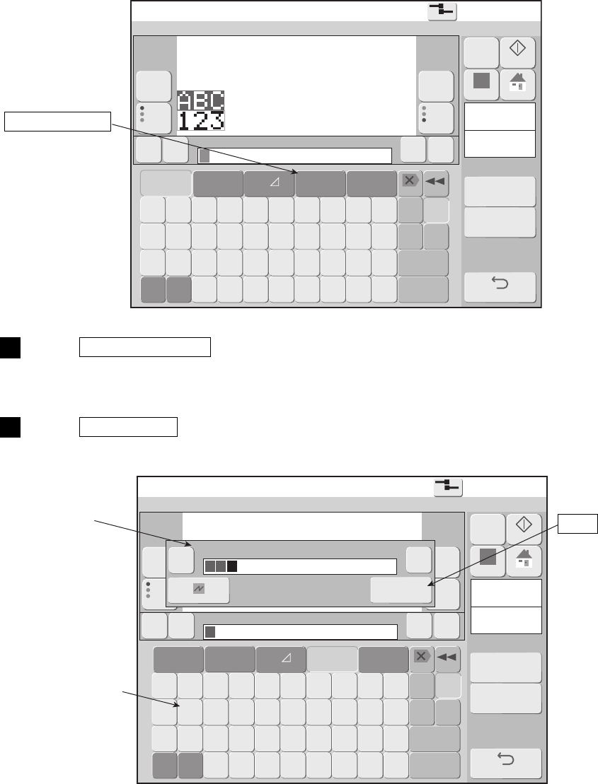
4-51 ●Update the print contents at a fixed interval (Time count)
Edit message [Stop ]
Message name[ ]
Calendar
/count
Edit message [Stop ]
Message name[ ]
Year
Month
Day Hour
Minu-
te
Seco-
nd
Total
days
Week
num-
ber
Day
of
week
Shift
code
Time
count
Count
Insert
Over-
write
Calendar
/ count
(2) Operation
The Edit message screen is displayed.
Press Calendar/count .
The display changes to the calendar/count keyboard and the calendar/count edit window are displayed.
1
Press Time count .
“FF” meaning time count is displayed at the calendar/count edit window.
2
Calendar/count
Calendar/count
edit window
Time count
OK

●Update the print contents at a fixed interval (Time count) 4-52
Edit message [Stop ]
Message name[ ]
Calendar conditions [Stop ]
Message name[ ]
1st screen
2nd screen
Calendar blocks:1/1
< Offset > < Substitution rules > < Zero-suppression >
Year
Month
Day
Hour
Minute
Press OK .
The calendar characters are displayed at the print contents edit area.
3
Touch the print item to input.
The character string of the print contents edit area is displayed at the print layout.
4
Press Cal. Cond. .
The Calendar conditions screen is displayed.
5
Press Previous or Next and change the objective calendar block.
6
Print layout
Print item to input
Calendar block is
displayed in a red
frame.
Calendar block is
displayed in a red
frame.
Time count
Calendar block No.

4-53 ●Update the print contents at a fixed interval (Time count)
Time count conditions [Stop ]
Message name[ ]
Range
Reset
Reset time hour minute
Renewal period
15 minutes
Press Time count .
The Time count conditions screen is displayed.
7
Input the range, reset value, reset time, and renewal period.
8
Press Back .
Returns to the Calendar conditions screen.
9
Back
Time count
conditions

●Use the count function 4-54
4.13 Use the count function
4.13.1 Print count characters
(1) Count characters
● Prints by changing the count value in the specified increments at each printing.
Count conditions screen setup items
Setup item Contents
Value Count value to be printed next.
Range (minimum, maximum) Range of count value. Set for each digit.
Update (In progress) Number of printings after the last count update.
Update (Units)
Count update printing cycle. Count is updated each printing the
number of update units.
Increment Change value of count value at count update.
Direction Selects whether counted up or counted down at count update.
Jump
(Jump from, Jump to)
After the count value matches the "Jump from:", the next count
value is made the "Jump to:".
Reset
When Count reset of the Print description screen is pressed, the
count value is changed to the specified value.
Count skip
Set capital alphabetical characters, small alphabetical characters
or user patterns to skip in count block.
Zero-suppression
Selects whether or not leading 0 except the rightmost end is to be
replaced by a space.
Multiplier
The value input here is multiplied by the count value and the
result is made the print contents.
● A series of count characters is called a "Count block".
Maximum Count block count
Model type Maximum Count block count
RX2-B 2
RX2-S
3
(Option : Up to 8)
● The count conditions are set for each count block.
● When there are multiple count blocks, the count conditions are set for each count block and each is
updated independently. There is no carry from another count block.
(Maximum digit : 20 digits/count block)

4-55 ●Use the count function
Count conditions [Stop ]
Message name[ ]
Value
Range
Update (in progress)
(unit)
1st screen
2nd screen 3rd screen
Count blocks:1/2
● A range button is not displayed at the Count conditions screen corresponding to a print item with bar code
set.
● When a jump digit was set at the right side of a count digit and jump occurred, the count of the digit at the
left of the jump digit is updated.
Count block
Count block is
displayed in a
blue frame.

●Use the count function 4-56
Value
Range
Update (in progress)
(unit)
Increment
Jump from:
to:
Reset
Count skip
down
up
Direction
Zero-suppression
Multiplier
Enable
Disable
Value
Range
(2) Count conditions setting examples
Number by +1 from "000" to "999".
1
Count result
000 001 002
998 999
(Note) Range is set for each digit.
When range is set to "001" to "999", since it means setting with "0"
excluded at the 1 position, the count result becomes as follows :
Count result
001 002 003 008 009
011 012 013 018 019
021

4-57 ●Use the count function
Value
Range
Update (in progress)
(unit)
Increment
Jump from:
to:
Reset
Count skip
down
up
Direction
Zero-suppression
Multiplier
Enable
Disable
Number by +1 from "A01" to "Z99".
2
Count result
A01 A02 A03 A98 A99
B01 B02 B03 B98 B99
Z01 Z02 Z03 Z98 Z99
(Note) Since the count value skips in increments when an increment is input,
always choose a count value for jump setting which is not skipped.

●Use the count function 4-58
Value
Range
Update (in progress)
(unit)
Increment
Jump from:
to:
Reset
Count skip
down
up
Direction
Zero-suppression
Multiplier
Enable
Disable
Set user pattern as count value
3
[Example] User pattern is defined as follows:
User pattern code 00
01 02 03 04 05 06 07
Definition pattern
31 2 4
4
3 2 1
When printing one way 4 times and backwards 4 times by both ways printing, the same
column can be printed by the same numbers ( to ).
The count result becomes as shown below.
1 4
● The user pattern which can be used in count are 48 kinds up to code 47
. Always use from top 00.
● Numeric and save characters can be combined.
[Example] Range [
0 0 0 0
]
[
9 9
0909 ]

4-59 ●Use the count function
Value
Range
Update (in progress)
(unit)
Increment
Jump from:
to:
Reset
Count skip
down
up
Direction
Zero-suppression
Multiplier
Enable
Disable
Print description [Ready ]
Ink operating time (hours)
Cumulative op. time (hours)
Print count (prints)
Ink pressure (MPa standard value: )
Message name[ ]
Reset the count value to a preset value.
4
Reset value "001" is set beforehand.
When Count reset is pressed, the count value is reset to
the preset "001".
Count reset

●Use the count function 4-60
Value
Range
Update (in progress)
(unit)
Increment
Jump from:
to:
Reset
Count skip
down
up
Direction
Zero-suppression
Multiplier
Disable
Enable
Print by replacing 0 of the count value with a space.
5
● "0" at the leading digit of the count character is replaced by a space and printed using the
zero-suppression function.
Count value "12" print comparison
Count conditions Print result
Zero-suppression disabled 0012
Zero-suppression enabled 12
Zero-suppression "Enable" is set.

4-61 ●Use the count function
Edit message [Stop ]
Message name[ ]
Edit message [Stop ]
Message name[ ]
Year
Month
Day Hour
Minu-
te
Seco-
nd
Total
days
Week
num-
ber
Day
of
week
Shift
code
Time
count
Count
Insert
Over-
write
Calendar
/ count
(3) Operation
The Edit message screen is displayed.
Press Calendar/count .
The display changes to the calendar/count keyboard and the calendar/count edit window are displayed.
1
Calendar/count
Calendar/count
edit window
Calendar/count
keyboard
Count character
OK

●Use the count function 4-62
Edit message [Stop ]
Message name[ ]
Year
Month
Day Hour
Minu-
te
Seco-
nd
Total
days
Week
num-
ber
Day
of
week
Shift
code
Time
count
Count
Insert
Over-
write
Calendar
/ count
Edit message [Stop ]
Message name[ ]
Input Count C (count character).
The count character is displayed on the calendar/count edit screen.
2
Press OK .
The count character is displayed at the print contents edit area.
3
OK
Count block is
displayed in a
blue frame.

4-63 ●Use the count function
Press Apply .
The character string of the print contents edit area is displayed in the print layout.
The count character input is applied.
4
Edit message [Stop ]
Message name[ ]
Press Count cond. .
The Count conditions screen is displayed.
5
Press Previous or Next and change the objective calendar block.
6
Press 1st screen , 2nd screen or 3rd screen and switch the count conditions
screen.
7
Count conditions [Stop ]
Message name[ ]
Value
Range
Update (in progress)
(unit)
1st screen
2nd screen 3rd screen
Count blocks:1/1
Count conditions
Objective count
block is colored.
Count conditions
screen switching
Count block No.
Changes the
objective
count block.
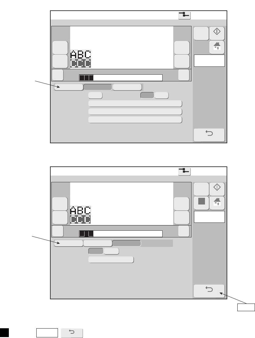
●Use the count function 4-64
Count conditions [Stop ]
Message name[ ]
2nd screen
1st screen 3rd screen
Count blocks:1/1
Increment
Jump from:
to:
Reset
down
up
Direction
Count conditions [Stop ]
Message name[ ]
3rd screen
1st screen 2nd screen
Count blocks:1/1
Zero-suppression
Multiplier
Enable
Disable
Press Back .
8
Count conditions
screen switching
Count conditions
screen switching
Back
4-65 ●Use the count function
4.13.2 Use count multiplication printing
(1) Function
● Prints by changing the count value in the specified increments at each printing.
● Multiplies the count value by a predetermined value and prints the result.
● Prints left-justified.
● Matches the decimal part of the product to the number of count digits by rounding off.
● Enables zero-suppression setting for the last 0 after the decimal point.
(Example: 1.230 → 1.23)
● When the number of digits of the integer part of the product exceeds the number of digits of the input
count character, a "Count Overflow" error is generated.
● When an integer value is set for the count multiplier, the zero-suppression setting is not reflected.

●Use the count function 4-66
Count conditions [Stop ]
Message name[ ]
3rd screen
1st screen 2nd screen
Count blocks:1/1
Zero-suppression
Multiplier
Enable
Disable
Edit message [Stop ]
Message name[ ]
(2) Operation
Shows the operation sequence when 0.3048 is set for the count multiplier and feet → meter converter
(1 foot → 0.3048 m) is performed and the result is printed.
Input Count C .
1
Press Count cond. .
The Count conditions screen is displayed.
2
Press Previous or Next and change the objective calendar block.
3
Press 3rd screen and switch the count conditions screen.
4
Display the 3rd screen of the count condition screens and input 0.3048 at the
count multiplier.
5
Count conditions
Count conditions
screen switching
Back
Multiplier

4-67 ●Use the count function
The count value is multiplied by the input count multiplier and the result is
printed.
A printing example is shown in the table.
(When both Disable and Enable are set at zero-suppression)
6
● When you want to return to normal count, input an invalid character at the count
multiplier to make the multiplier invalid.
● When a bar code is set for a count print item, a mask is applied to the count multiplier
input area and count multiplier cannot be input.
● Integer values can be input at the count multiplier.
● Alphabet, symbols, and saved characters cannot be input at the count multiplier.
Precautions when using count multiplication printing
Printing example of count multiplication printing (zero-suppression disabled)
Input characters C C C C C C
Count multiplier 0 . 3 0 4 8
Zero-suppression Disabled
Initial value Product Printed result Remarks
0 0 0 0 0 1 0. 3 0 4 8 0. 3 0 4 8 -
0 0 0 0 0 2 0 . 6 0 9 6 0 . 6 0 9 6 -
……… -
0 0 0 0 1 0 3. 0 4 8 0 3. 0 4 8 0 -
0 0 0 0 1 1 3 . 3 5 2 8 3 . 3 5 2 8 -
……… -
3 2 8 0 8 2 9 9 9 9 9 . 3 9 3 6 9 9 9 9 9 Digits which cannot be printed are rounded off.
3 2 8 0 8 3 9 9 9 9 9 . 6 9 8 4 1 0 0 0 0 0 Digits which cannot be printed are rounded off.
……… …
9 9 9 9 9 8 3 0 4 7 9 9 . 3 9 0 4 3 0 4 7 9 9 Digits which cannot be printed are rounded off.
9 9 9 9 9 9 3 0 4 7 9 9 . 6 9 5 2 3 0 4 8 0 0 Digits which cannot be printed are rounded off.
Printing example of count multiplication printing (zero-suppression enabled)
Input characters C C C C C C
Count multiplier 0 . 3 0 4 8
Zero-suppression Enabled
Initial value Product Printed result Remarks
0 0 0 0 0 1 0. 3 0 4 8 0. 3 0 4 8 -
0 0 0 0 0 2 0 . 6 0 9 6 0 . 6 0 9 6 -
……… -
0 0 0 0 1 0 3. 0 4 8 0 3. 0 4 8 Last decimal digit is zero-suppressed.
0 0 0 0 1 1 3 . 3 5 2 8 3 . 3 5 2 8 -
……… -
3 2 8 0 8 2 9 9 9 9 9 . 3 9 3 6 9 9 9 9 9 Digits which cannot be printed are rounded off.
3 2 8 0 8 3 9 9 9 9 9 . 6 9 8 4 1 0 0 0 0 0 Digits which cannot be printed are rounded off.
……… …
9 9 9 9 9 8 3 0 4 7 9 9 . 3 9 0 4 3 0 4 7 9 9 Digits which cannot be printed are rounded off.
9 9 9 9 9 9 3 0 4 7 9 9 . 6 9 5 2 3 0 4 8 0 0 Digits which cannot be printed are rounded off.
*Count characters are represented by C and spaces are represented by .

●Use the count function 4-68
Value
Range
Update (in progress)
(unit)
Increment
Jump from:
to:
Reset
Count skip
down
up
Direction
Zero-suppression
Multiplier
Enable
Disable
4.13.3 Skip specified character and print (Count skip)
(1) Function
● Skip the character which was set and move to the next count value to print.
● "Count skip" characters is either one kind of capital alphabetical character, small alphabetical character or
user pattern.
● Up to 5 characters can be input as "Count skip" characters.
● The range of each digit to which count character is input may vary, however, the "Count skip" character
may not exceed the range of each digit.
(2) "Count skip" setting examples
Skip the alphabet "I" and count up by an increment of 1 from "000" to "ZZZ".

4-69 ●Use the count function
Count conditions [Stop ]
Message name[ ]
Count blocks:1/1
Value
Range
Update (in progress)
(unit)
1st screen
3rd screen2nd screen
(3) Operation
The procedures to skip the alphabets "I" and "Q" ,which are inputted to "Count skip" are shown below.
Input Count C .
1
Edit message [Stop ]
Message name[ ]
Press Count cond. .
The Count conditions screen is displayed.
2
Press Previous or Next and change the objective conut block.
3
Set Range using numeric, capital alphabetical character, small alphabetical
character or user pattern.
Numeric cannot be set to Range (maximum) when count skip is used.
Open the 1st screen of Count conditions screen and input Value and Range.
4
Count conditions
Count conditions
screen switching
Range (maximum)

●Use the count function 4-70
Count conditions [Stop ]
Message name[ ]
1st screen
3rd screen2nd screen
Count blocks:1/1
Increment
Jump from:
to:
Reset
Count skip
down
up
Direction
Press 2nd screen and switch Count conditions screen.
Input "I" and "Q" at "Count skip" on the 2nd screen of Count conditions.
5
Count conditions
screen switching
Count skip
Skip the characters inputted to "Count skip", then print the next count value.
See the figure below for print example.
6
● When the "Count character" is added, overwritten or deleted, the confirmation
message "Changed skip condition" shows up on the screen and "Count skip"
character becomes invalid.
● As to Range (maximum), input either one kind of capital alphabetical character, small
alphabetical character or user pattern.
In addition, all "Count skip" characters must be included in the smallest range.
● Characters which were set as Value, Range, Jump or Reset cannot be input to "Count
skip".
● When the "Count skip" is set, the incremental value is 1=fixed.
Precautions when using count skip printing

4-71 ●Set the print specifications
Print specifications [Stop ]
Message name [ ]
Ink drop use
Character width
1/1 16
0 3999
Character height 0 99
Character
orientation
Printing method Single scan Interlaced Mixed
Print start
delay
Arrow : Prin-
ting direction
Print start delay
0 9999 SC
Sensor Print start
0: 1:
2:
3:
1st screen
2nd screen 3rd screen
4.14 Set the print specifications
4.14.1 Set the character height, character width, and orientation
(1) Function
● Sets the character height, character width, character orientation, and print start.
Character height
● The character height can be specified.
1
3
Ink drop use percentage setting Character width setting
1/1 002 *
1/2 001
1/3 to 1/16 000
Ink drop use percentage
● Sets the ratio of drops used in printing. For example, ink drop use 1/3 prints at a ratio of 1 in 3 ink
drops. The 2 ink drops are recovered from the gutter.
2
Setting range of ink drop use percentage
Model type 1 line 2 lines 3 lines Notes
RX2-B 1/3 to 1/16 1/4 to 1/16 1/4 to 1/16 -
RX2-S 1/2 to 1/16 1/2 to 1/16 1/2 to 1/16 Option : Up to 1/1
● When ink drop use is 1/1 or 1/2, high speed printing is possible. For ink drop use 1/16, low speed
printing is performed and the print quality improves.
● When Format setup is Free layout on the Change message screen, setting range of ink drop use
percentage is 1/2 to 1/16.
Character width
● The character width can be specified.
● The character width setting range is from 0 to 3999.
● When the product speed matching feature is incorporated (when the rotary encoder is connected),
set the character width as indicated below.
Changes the print start
delay input units.
Screen
switching

●Set the print specifications 4-72
Display of Printing method
Icon Ink Drop Charge Rule Classification Printing method
Standard (Single scan)
When there are multiple printing lines,
multiple lines are printed in turn.
Standard (Interlaced),
Dot mixed interlaced
Multiple lines are printed at the same
time.
Mixed single scan and interlaced
Printing is done while switching
between single scan and interlaced for
each column.
Setting Direction of transport Printing results
0 : A B C a← A B C 1 2 3
→
→b
1 : A B C a←
←
→b A B C 1 2 3
2 : a←
←
→b
3 : a←
→
→b
A B C 1 2 3
A B C 1 2 3
Character orientation
● Printing direction of characters can be set.
● Settings and print results are as shown below.
4
A B C 1 2 3
A B C
A B C
A B C 1 2 3
A B C 1 2 3
A B C 1 2 3
Direction of transport
Example of setting "0:ABC→"
and Direction of transport "a".
a
b
Printing method
● Two printing methods are selectable: "single scan", "interlaced" and "mixed".
● A printing method will be automatically selected in accordance with the print format setup and
the ink drop charge rule.
5
No. Setup screen Items Setting
1
Print specification
Product speed matching Encoder
2 Ink drop use 1
3
High speed print mode "HM"
4 User environment setup Print data changeover error "Enable"
* The conditions where "Character width" can be set to "0" are described in Table below.
When "Character width" is set to "0" and "
Product speed matching" is set to "Encoder".
(i) The conveyor speed is detected by the encoder and the character width is set and fixed by that
speed detected. If the print object is slipped on the conveyor or its transfer speed fluctuates
substantially while the print object is passing the object sensor and the printing is completed,
the print start delay variation or the character width variation is expected. Please be sure to
conduct test printing and confirm whether there is any variation of print start delay or the
character width. If the substantial variation is observed, please set the Character width to 2 or
more.
(ii) The item on "Adjust printer parameters" screen are not available.
(iii) The conveyor speed is caculated print by print. Therefore "Print start delay".
(iii) The conveyor speed is caculated print by print. Therefore "Print start delay" will become
longer by 30 scans than that of "Encoder" due to its calculation time.
(iv) The number of print formats will be four (4) or less.
● For rotary encoder wiring and setup, see the Technical Manual "4.3.2-1 Rotary encoder
specifications, wiring and switch setting".

4-73 ●Set the print specifications
When the nozzle is positioned before the sensor When the nozzle is positioned after the sensor
Print start delay=a-b (mm) Print start delay=a+b (mm)
Print start delay
● The printing start position can be specified.
● After setting in character units or mm units, fine adjust in scan units.
● When you want to input in mm units, input "Line speed".
● The positional relationship between the sensor and nozzle is as indicated below.
6
● Specify the print start delay (printing start position) as suggested below.
(i) Measure the length of the print start delay.
(ii) Measure the inter-character distance (C).
(iii) Divide the value obtained in (i) by the value obtained in (ii). Enter the resulting value.
a+b
c
: Setting value
● When a product speed matching function is not provided, if the ink drop use percentage, character
width, character size or number of lines is changed, the set value of the print start delay can be adjusted
so that the time until printing starts will not change.
● When a product speed matching function is provided, if the pulse rate division actor is changed, the set
value of the print start delay can be adjusted so that the time until printing starts will not change.
Sensor
c
Direction of transport
Print target
b
Nozzle center
a
0 0 2 3
Sensor
c
Direction of transport
Print target
b
Nozzle center
a
0 0 2 3
Print specifications
2015.07.07 12:45
Com=0
[Stop ]
Message name [ ]
Product speed matching
Line speed [m/min.] Input '0' if unknown
Pulse rate div. Factor 1/1 999 Enter denominator.
Speed compensation
Speed compensation fine control (-50 +50)SC
Distance between print head and work [mm]
Repeat print
Repeat count (0: none, 1 9998, 9999: Continuous)
Repeat intervals 0 99999 SC
2nd screen
1st screen 3rd screen
Enable
None
Encoder
Auto
2nd screen of "Print specifications" screen
Changes the repeat
intervals input units.
Screen switching
● When making interlaced prints, perform the following setup.
(i) Ensure that the same print format is employed for all items.
(ii) Ensure that the same line count setting is employed for all columns.
(iii) The ink drop use percentage is 1/1 to 1/4.
Perform overall column setup. The format for the first item is
then applied to all the other items so as to provide interlaced
setup. When making a 1-line print, the single scan predominates
even if you perform steps (i) through (iii) .
● In the case of free layout, printting method is single scan fixed.
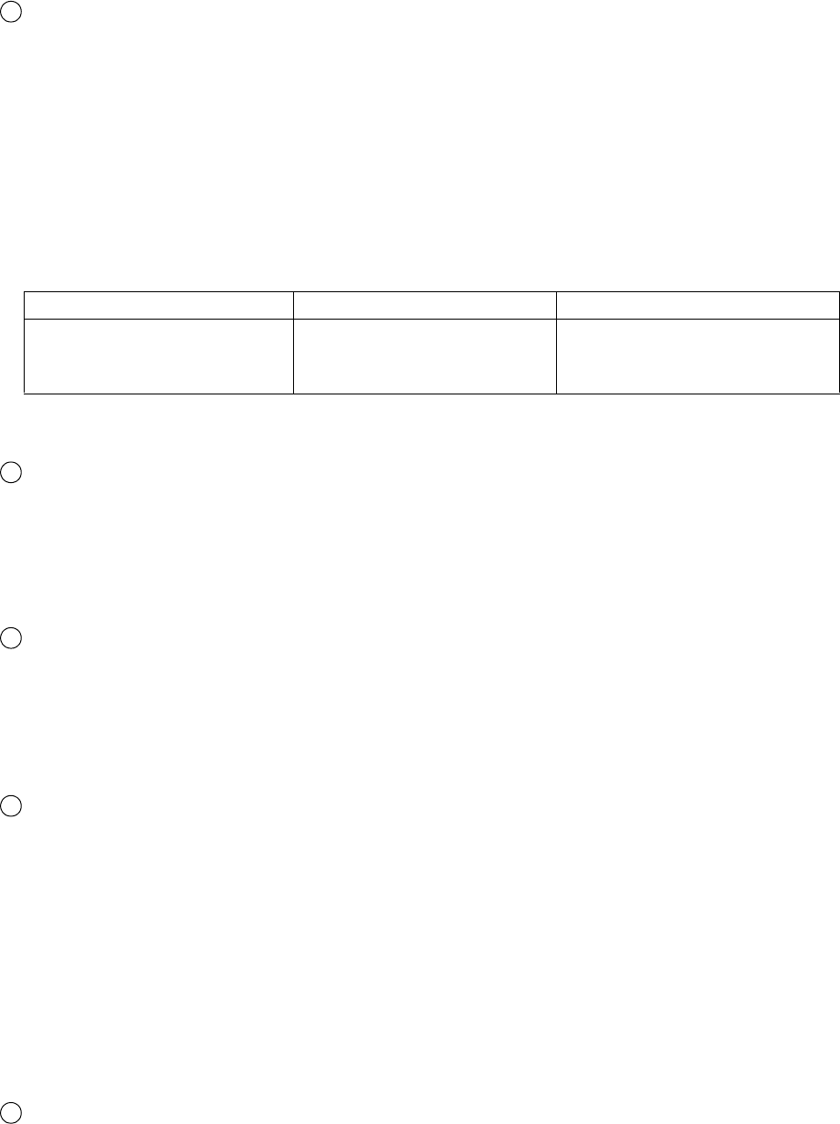
●Set the print specifications 4-74
Product speed matching
● When printing is conducted with this feature activated, the character width is maintained
irrespective of the print target transport speed changes.
● The Printing by "Auto" method is performed according to the change of speed without a rotary
encoder.
● Enter "Print Target width" and "Actual Print width" in mm for "Auto".
● "Repeat count" and "Target sensor filter: Until end of printing" on "Print specifications" can not
be used when setting "Auto".
Refer to "4.3.5 Product speed matching function without a rotary encoder" of the Technical
Manual for "Auto" method.
7
Difference between product speed matching setting
None Encoder Auto (RX2-S only)
Prints per individual scan for
an interval of a definite period
of time.
Printing is performed scan by
scan at each encoder pulse.
Printing is performed according
to the change of speed.
Refer to "4. Electric signal connection" of the Technical Manual for details.
8
9
10
Line speed
● Inputs the line speed.
● When the line speed was input, the print start delay and repeat intervals set values can be input in mm
units by pressing change unit.
● The selectable setting ranges from 0 to 999.9 m/minutes.
● This feature cannot be activated if the product speed matching feature is enable.
Pulse rate division factor
● Specifies the pulse rate division Factor that determines the intervals at which the encoder signal is to be
recognized.
● The selectable setting ranges from 1/1 to 1/999.
● When a setting of 1/1 is selected, no pulse rate division Factor is effected.
● This feature cannot be activated if the product speed matching feature is disabled.
Speed compensation (RX2-S)
● Set to prevent changes in the print position.
● Cannot be set when a Product speed matching feature is not specified.
● Adjusts print start delay according to the set value of "Distance between print head and work".
● Cannot be used when Repeat print is specified.
● Note that a Print Overlap Fault may be generated when the printing interval is extremely short when
the Speed compensation setting is changed from "Disable" to "Enable".
● Fine adjusts the print start delay from the setting value of the Speed compensation fine control.
However, the following condition must be satisfied.
0 [Print start delay]+[Speed compensation fine control]
● Set values for "Speed compensation" and "Speed compensation fine control" are not memorized per
print date but held as a common value.
Distance between print head and work.
● Inputs the distance between the print head and the print target.
● When product speed matching is "encoder" and "Speed compensation" was set to "Enable", the print
start delay is adjusted by considering the distance between the print head and the print target.
When "Speed compensation" is set to "Disable", the distance between the print head and the print
target is not referenced, even if set.
11
<
=

4-75 ●Set the print specifications
Print specifications
2015.07.07 12:45
Com=0
[Stop ]
Message name [ ]
Target sensor timer 1/10sec 0: none 1 999
Target sensor filter
Setup value (ms 0 9999)
Ink Drop Charge Rule
Standard(single : It prints by the Single scan or Interlaced.
scan/interlaced)
3rd screen
1st screen 2nd screen
Until end of print.
Time setup
Standard(single scan/interlaced)
Screen switching
Print specifications
2015.07.07 12:45
Com=0
[Stop ]
Message name [ ]
Product speed matching
Print Target width (mm 0 9999)
Actual Print width (mm 0 9999)
Speed compensation
2nd screen
1st screen 3rd screen
Enable
None
Auto
Encoder
12
Print Target width
● Enter "Print Target width" in mm for "Auto".
Input the length of the place over which the print target is detected.
● The Print Target width setting range is from 0 to 9999.
● If "Print Target width" is not entered, the print is made with the same interval as when the Speed
matching function is not used.
Actual Print width
● Enter "Actual Print width" in mm for "Auto".
● The Actual Print width setting range is from 0 to 9999.
● The value for "Actual Print width" must be smaller than "Print Target width".
● If "Actual Print width" is not entered, the print is made with the same interval as when the Speed
matching function is not used.
13
3rd screen of “Print specifications” screen
Print Target width
ABC
Actual Print width
The place over which
the print target is detected.
12
13

●Set the print specifications 4-76
14
● The term "chattering" refers to a state where signal voltage instability occurs when the sensor
signal starts or ends.
Target sensor timer
● You can specify the time for displaying a fault message when the sensor is continuously ON.
● When the sensor on time exceeds a set value, the message "Target Sensor Fault" is displayed.
● If the "Target sensor timer" feature is not needed, select a setting of 0.
● The selectable setting is from 0.0 to 99.9 seconds.
Target sensor filter
● Perform this setup when you intend to maintain operation normality even in the event of chattering.
● The time for ignoring chattering is set for when a sensor signal chatters when printed matter shields the
sensor from light.
● When a fault occurs due to chattering, the message "Print Overlap Fault" is displayed.
● If the target sensor filter feature is not needed, select a setting of 0.
● The selectable setting ranges from 0 to 9999 milliseconds.
● "Target sensor filter: Until end of printing" can not be used when setting "Auto" on "Product speed
matching".
15
16
Ink drop charge rule (RX2-S only)
● There are three rules of Standard, Mixed single scan and interlaced, and Dot mixed interlaced in the
Ink Drop Charge Rule.
● With this function, print quality will be better than the case that dot mixture data is printed by the
single scan especially when ink drop use is from 1/1 to 1/4.
Differences of each rule of the Ink drop charge rule
Method Print sample
Standard (Single scan)
Standard (Interlaced)
Mixed single scan and interlaced
Dot mixed interlaced
All the columns are printed by single scan.
(Column 1) (Column 2) (Column 3) (Column 4) (Column 5)
5
×8
5
×8
5
×812×16 12×16 7×10 5×8
All the columns are printed by interlaced.
(Column 1) (Column 2) (Column 3) (Column 4) (Column 5)
5
×85×85×85×85×8
5
×85×85×85×85×8
Rules are changed by column.
(Column 1) (Column 2) (Column 3) (Column 4) (Column 5)
5
×85×8
5
×87×10 5×5
5
×87×10 12×16 5×55×5
Interlaced Single scan Single scan Interlaced Single scan
All the columns are printed by interlaced.
(Column 1) (Column 2) (Column 3) (Column 4) (Column 5)
5
×8
5
×85×87×10
12
×16 5×85×818×24 7×10

4-77 ●Set the print specifications
● When the conditions in the following table are met during mixed single/interlaced control, printing that
mixes single scan and interlaced is possible.
Conditions for interlaced printing at Mixed single scan and interlaced
No. Conditions Example of print data
1 Barcodes are not set.
2
When number of line is two or more, all fonts of
items in each column are the same.
3
Ink drop use is from 1/1 to 1/4.
(The high speed print is not applicable.)
(Column 1) (Column 2) (Column 3)
5
×8
7
×10 5×8
18
×24 7×10 5×8
Single scan Interlaced
● When the conditions in the following table are met during dot mixed interlaced, interlaced printing with
mixed dots is possible.
Conditions for interlaced printing at Dot mixed interlaced
No. Conditions Print example
1 All fonts of items in each column are the same.
2 Barcodes are not set.
3
Following (1) or (2) is satisfied in all columns.
(Interlaced printing is also possible when all
columns are configured only with the condition
(2).)
(1) When number of line is two or more
All fonts of items in each column are the
same.
(2) When number of line is one
The font of items is 12
×16 or 18×24.
4
Ink drop use is from 1/1 to 1/4.
(The High-speed print mode is not applicable.)
(Column 1)
(Column 2) (Column 3)
5
×8
7
×10 5×8
18
×24 7×10 5×8
Interlaced
● 1-line columns with 12×16 or 18×24 font at Dot mixed interlaced will be split into 2-line (or 3-line) in
the IJP and printed. As a result of a sprit 1-line of 12
×16 or 18×24, borders of characters might look
being pushed down, and set the Line spacing only for the case.
But, uneven printing happens when product speed matching is used at low speed .
● The number of print formats that can be set with dot mixture is up to eight at all ink drop charge rules.
And the ink drop use can not be mixed.
● Ink Drop Charge Rule Precautions
Precautions
No. Precautions Conditions
1
The higher the speed the bigger misalignment of lines at high speed without
product speed matching.
Dot mixed
interlaced only
2
Uneven printing happens at divided positions when product speed matching
is used for 1-line printing at low speed.
Dot mixed
interlaced only

●Set the print specifications 4-78
4th screen
2nd screen 3rd screen
First row width
Secind row width
1st screen
Avoid shrink of leading character
Leading character with control
Print specifications [Stop ]
Message name[ ]
2015.07.07 12:45
Enable
Disable
Leading character width control (RX2-S only)
● Set to prevent shrinking of the leading print character width at high speed line printing.
● Can be set when product speed matching is "None" "Enhance".
● As a means of preventing shrinking of the leading character width, unprinted particles are inserted at
the "First line width" and "Second line width" of the leading print character.
● The number of unprinted characters that can be inserted is 0 to 32.
Necessary conditions for leading character width control
No. Item Conditions
1 Product speed matching Set to None or Enhance.
2 The number of lines
[Print format: Individual setup, Overall setup]
Set the number of rows to 1 row or 2 rows.
[Print format: Free layout]
Not special setting.
3 Ink drop use
[Product speed matching: None]
Set Ink drop use to 1/1 or 1/2.
[Product speed matching: Enhance]
Set Ink drop use to 1/1.
4 Character size
[Ink drop use: 1/1]
All character sizes can be used.
[Ink drop use: 1/2]
Set the character size 4
×5, 5×5, 5×8(5×7), 9×8(9×7),
7
×10, 5×3 (chimney), 5×5(chimney), or 7×5(chimney).
17
Page 4 of "Print specifications" screen
● When all the necessary conditions of 1 to 4 below are satisfied, leading character print control is enabled.

4-79 ●Set the print specifications
● The recommended value when setting by leading character width control depends on the number of
vertical dots.
<Vertical dots calculation method>
◯ Print format: Individual setup, Overall setup
Vertical dots=First line character size + Second Line character size
◯ Print format: Free layout
Vertical dots=Item Y coordinate+ character size
Leading character width control recommended values
Leading character
width control
Ink drop use: 1/1 Ink drop use: 1/2
First row width Second row width First row width Second row width
1 6332
2 6332
3 6332
4 5232
5 4221
6 4221
7 4221
8 4221
9 3110
10 3110
11 2100
12 2100
13 2100
14 2100
15 2100
16 2100
17 1000
18 1000
19 1000
20 1000
21 1000
22 1000
23 1000
24 1000
25 1000
26 1000
27 1000
28 1000
29 1000
30 1000
31 1000
32 1000

●Set the print specifications 4-80
4.14.2 Set repeat printing
(1)Overview
● This is set to print the same print description continuously.
● Set the "Repeat intervals" and "Repeat count" for repeat printing.
● Repeat printing can not be used when setting "Auto" on "Product speed matching".
Repeat intervals
● The print target size can be specified.
● This setup is to be performed when the print target is transported while it is in close contact.
● After setting in character units or mm units, fine adjust in scan units.
● When you want to input in mm units, input “Line speed”.
● Perform the following calculations for repeat intervals setup purposes.
(i) On an individual scan basis
(1-digit character width × number of digits - trailing character correction value)
× (print target size/all-digit print width)
(ii) On an individual character basis
Number of digits × (print target size/all-digit print width)
1
● 1-digit character width = (horizontal character size + inter-character space)
× character
width increase setting
● Trailing character correction value = inter-character space
× character width increase
setting + 1
(Example) Print target size: 64 mm; all-digit print width: 25 mm;
number of digits: 6; character size: 5 × 7 dots; inter-character space: 2 dots
● On an individual scan basis
((5+2)×1×6-(2×1+1))×(64/25)=99.84→100
● On an individual character basis
6×(64/25)=15.36→15
● Round off the calculation results to the nearest whole number.
Repeat count
● You can preset the number of repeats.
● If repeat printing is not needed, set the number to "0".
● Printing is performed in accordance with the repeat printing mode setup.
● The relationship between the repeat printing mode and the count is as stated below.
2
Mode
Setting
2 to 9998 9999
Signal ON
period
Printing is repeated a preselected
number of times at predefined
intervals while the print target is
detected.
Repeat printing is performed
while the print target is detected.
OFF - ON
transition
Printing is repeated a preselected
number of times at predefined
intervals once the print target is
detected.
Once the print target is detected,
repeat printing is performed until
it is aborted.
Print target Print target
Repeat intervals

4-81 ●Set the print specifications
4.14.3 Set various printing
(1) Function
“Various print setup” screen
Calendar offset
● Sets whether to make it today or yesterday when finding whether the calendar month or year offset is set.
DIN print (RX2-S only)
● Rotated 180° and printed at each printing so that characters can also be read by viewing from the top or
bottom.
● At repeat print setup, printing is rotated 180°at the end of one printing.
1
2
● Following shows conditions to execute DIN print.
Conditions for DIN print
No. Condition
1 All print items are a 1 line setting..
2 The character size of all the print items is the same.
3 No barcode item.
4 No Calendar item.
5 Format setup is not free layout.
Line direction
A B C A B C
A B C
[Printing 1] [Printing 2]
[Printing 3]
Work
DIN printing example
Various print setup [Stop ]
Message name [ ]
Calendar offset
DIN print
EAN Prefix
Barcode printing
QR Error correction level
Revers scan print
High quality mode
Offset from yesterday
From today
Disable
Enable
Print format
Edit message
Normal
Reverse
M (15%)
Q (25%)
Disable
Enable
Disable
Enable

●Set the print specifications 4-82
Error correction level Data restoration percentage
M Approx. 15%
Q Approx. 25%
EAN Prefix (RX2-S only)
● Whether to set bar code EAN-13, EAN-8 country code by character input or print format is selected.
3
Number of digits of bar code
Country code Data Check digit Total number of digits
EAN-13 2 10 1 13
EAN-8 2 5 1 8
EAN Prefix
Set value
Character input Print format
Handling of country code
Country code is input at the head
of the data.
Set by print format without
including country code in the
data.
Print format screen Country code is not displayed. Set the country code.
Edit message screen
For EAN-13, input 12 digits and
for EAN-8, input 7 digits, all
including the country code.
However, check digit is
excluded.
For EAN-13 input 10 digits and
for EAN-8, input 5 digits, with-
out including the country code.
However, the check digit is
excluded.
Normal
The barcode dot data will be printed as is.
(With yellow ink, a yellow bar is created.)
Reverse
The barcode dot data will be reversed and printed.
(The work color will become the color of the bar. The ink color will be that
of background.)
● When the country code is changed at the Print format screen, the country code for all the bar
code items in that message is changed to the same value.
● For UPC-A, input 11 digits including the prefix code at the edit message screen.
Barcode print (RX2-S only)
● Set the barcode print system.
● The white areas (quiet zone) are necessary at both ends of barcode for the barcode to be recognized.
Input one or two characters with all dots marked out (provided on numeric keyboard screen) to the
previous column and next column items.
● For DM codes, QR codes and DotCode printing will be performed in normal mode even if reverse is
selected.
For DM codes, QR codes and DotCode process data to reverse mode at reader side before reading.
● When adding Human Readable code, the barcode dot data is printed as is, even if set "Reverse".
4
Normal
Reverse
Quiet zone
QR Error correction level (RX2-S only)
● Choose an error correction level from "M" or "Q".
See the Technical Manual "9. APPENDIX" for details.
5

4-83 ●Set the print specifications
Adjust print parameters [Stop ]
Character height 0 99
Character width 0 3999
Print start delay 0 9999 SC
Pulse rate div. Factor
Message name [ ]
(1/1 1/999 Enter
denominator.)
4.14.4 Fine adjust the print specifications (Adjust print parameters)
(1) Function
● Starts from the Print description screen.
● Current message print specifications "character height”, "character width", "print start delay" and "Pulse rate
div. Factor" settings are easily set.
● Since changes to the set value are immediately reflected in the printing, the changes be easily confirmed while
printing.
● After setting in character units or mm units, fine adjust in scan units.
● When you want to input in mm units, input "Line speed" in the print specifications screen.
"Adjust print parameters" screen
(Note) If various settings are changed when the printing is performed frequently,
the faults such as "Print Overlap fault", "Print Data Changeover In
Progress V" or "Invalid Print Start Timing" may occur.
Reverse scan printing (RX2-S only)
● Selects whether or not reverse scan control which deflects the particles in the reverse order of the
conventional order is to be used.
● The printing tilt when the print target is transported at high speed becomes smaller than the
conventional control system.
Refer to "9. Appendix" of the Technicial manual for more information.
6
High quality mode (RX2-S only)
● By using this function, better printing quality would be obtained than normal one particularly when
the product speed matching function is applied to print something at low speed, if a specific dot
pattern which lessens a distortion of printing is adopted.
Refer to "9. Appendix" of the Technical manual for more information.
7
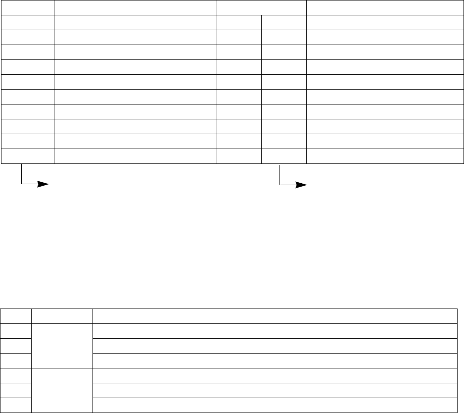
● Using the AI code input support function (RX2-S only) 4-84
4.15 Using the AI code input support function (RX2-S only)
(1) Function
● "AI code" is the abbreviation for "Application Identifier".
AI code is an identification code that manages the data items attached to the head of a product code,
expiration date, quantity, lot No., and various other data, and is represented by a 2 to 4 digit number.
● AI code is used with barcode standards established by GS1.
"GS1" is the abbreviation for "Global Standard One". It is an international organization that designs and
proposes international standards.
● Items set by 4 kinds of barcodes (Code128, DM, QR or micro QR) can use the AI code input support function.
● The following AI codes can be input by AI code input support function.
AI code Data item Data length Character types that can be input
01 GTIN Fixed 14 Numeric
10 Batch or Lot Number Variable 20 Alphanumeric/ASCII symbols
11 Production Date Fixed 6 "YYMMDD" fixed or numeric
15 Best Before Date Fixed 6 "YYMMDD" fixed or numeric
17 Expiration Date Fixed 6 "YYMMDD" fixed or numeric
21 Serial Number Variable 20 Alphanumeric/ASCII symbols
30 Variable Count Variable 8 Numeric
91 Company Internal Information Variable 30 Alphanumeric/ASCII symbols
310* Net Weight - Kilograms - Trade Fixed 6 Numeric characters
320* Net Weight - Pounds - Trade Fixed 6 Numeric characters
No. Data length Condition
1
Fixed
Number of input characters does not match the data length.
2 A character other than an input able character was input.
3 Seven or more characters were set at the * part of AI code (310*) and (320*).
4
Var ia bl e
Number of input characters exceeds the data length.
5 A character other than an input able character was input
6 "FNC1" code was input at other than the beginning or end of an item.
*Indicates the number of digits after
the decimal point.
(0 to 6 can be input.)
Variable length is the maximum
number of characters.
● "FNC1" code must be added at the end of "Variable" data length items.
("FNC1" indicates the end of the variable length code.)
If "FNC1"is not input, the system will add it automatically
● If even one of the following conditions is satisfied, "Invalid Barcode" will be displayed.
*The AI code itself (2 to 4 digits) is not included in the input character count.
*The "FNC1" code at the end of a data length "Variable" item is not included in the input character count.

4-85 ● Using the AI code input support function (RX2-S only)
Edit message [Stop ]
Message name[ ]
2015.07.07 12:45
Edit message [Stop ]
Message name[ ]
2015.07.07 12:45
(01) : GTIN
(10) : Batch or Lot Number
(11) : Production Date
(15) : Best before Date
(17) : Expiration Date
Prev.Dsp. Next Dsp.
(2) Operation
The Edit message screen is displayed.
Select AI from the input mode.
AI code list is displayed.
1
AI
AI code list

● Using the AI code input support function (RX2-S only) 4-86
Edit message [Stop ]
Message name[ ]
2015.07.07 12:45
Select (11): Production Date from the AI code list.
[11 YYMMDD] is automatically input at the barcode item.
2
Press Apply .
The character string of the print content edit area is displayed on the print layout.
3
AI
Apply

5-1 ●Maintenance
Maintenance menu [Ready]
Unit information
Operation
management
Test print
Excitation V update
(Nozzle test)
View alarm
history
Circulation control
View software
version
Comm. monitor
Password
protection
Solenoid valve/
pump test
(1) Functions
5. MAINTENANCE
Item Description Reference
Unit information ●Displays the unit TYPE-FORM, serial number, etc. 5.1
Operation management ●Displays the operational status. 5.2
Test print ●Prints without any start print signal input. 5.3
Excitation V update
(Nozzle test)
●Finds the optimum excitation V-ref. value to
maintain good print quality.
Technical Manual
6.11
View alarm history
●Displays the generation status of error and alarm
messages.
9.3
Circulation control ●Controls the ink and makeup circulation system. Technical Manual 6
View software version ●Displays the name of the registered software. 5.4
Comm. monitor
●Displays the description of the serial
communications between an external device and the
IJ printer.
Technical Manual
5.6
Password protection ●Displays the functions that can be executed. 5.5
Solenoid valve / pump
test
●Checks the operation of the solenoid valve and
pump.
Technical Manual
6.14
(2) Operation
Press Maintenance in the Print description screen.
The maintenance menu screen is displayed.
1

●Confirm the Unit information 5-2
Unit information [Ready ]
TYPE-FORM
Serial number
Ink type
RX2-SD160W
99999999
JP-K69
5.1 Confirm the Unit information
(1) Functions
●Displays the unit TYPE-FORM, serial number, login information, and ink type.
Item Description
TYPE-FORM ●Displays the TYPE-FORM of the unit.
Serial number ●Displays the serial number of the unit.
Ink type ●Displays the type of ink used.
Upgrade (RX2-S only) ●The Upgrade condition can be confirmed by pressing Upgrade .
(2) Operation
Press Unit information in the Maintenance menu.
1

5-3 ●Confirm the Unit information
Item Description
Ink operating time
(variable value)
●Displays the operating time from the last ink replacement.
●At ink replacement, set to “0”. Displays up to 9,999 hours.
●When the Ink alarm time is exceeded, displays an ink replacement alarm message.
Ink alarm time
●Displays the time which becomes the ink replacement standard.
●Always displays the standard value.
Cumulative op. time
●Displays the cumulative operating time. The value cannot be changed.
●Displays up to 999,999 hours.
Print count
(variable value)
●Displays the number of printings.
●A value of 0 to 999,999,999 can be set.
Ink name ●Displays the type of ink used.
Makeup name ●Displays the type of makeup used.
Ink viscosity
●Displays the ink viscosity
●Standard value is 100.
Ink pressure
●Displays the ink pressure.
●The standard value is always displayed.
Ambient temperature ●Displays the ambient temperature and allowable ambient temperature.
Deflection voltage ●Displays the deflection voltage in the Ready state.
Excitation V-ref. ●Displays the set excitation V-ref. value.
Excitation frequency ●Displays the nozzle excitation frequency.
Operation management [Ready ]
Ink operating time
Ink alarm time
Cumulative op. time
Print count
Ink, makeup JP-K69, TH-TYPE A
Ink viscosity 100 (standard value:100)
Ink pressure 0 250 (MPa; standard value: 0 250)
Ambient temperature 20 ( ; range: 0 45)
Deflection voltage 5. 7 (kV)
Excitation V-ref. 11 (0 19)
Excitation frequency 68. 9 (kHz)
(hours)
(hours; standard value: 1200)
(hours)
(prints)
5.2 Monitor operational status
(1) Functions
● Displays the operational status of the IJ printer.
● Saves the Ink operating time and Print count once an hour (1 minute each hour).
When there was a power failure, returns to the previously saved state.
● The following items are also displayed in the Print description screen (initial menu).
(Items displayed in Print description screen: Ink operating time, Cumulative op. time, Print count, Ink pressure.)
(2) Operation
Press Operation management in the Maintenance menu.
1

●Print without any sensor signal. (Test print, Start printing) 5-4
Test print [Ready ]
Printing starts at the press of [Start printing].
5.3 Print without any sensor signal (Test print, Start printing)
(1) Functions
●This function prints by button operation without a print start signal being input.
●Print can also be performed by pressing Start printing from the manual control menu when in print ready
status.
(2) Operation
Verify that the printer is in “Standby” state.
Press Test print in the Maintenance menu.
1
Press Start printing .
Printing starts.
2
(Note) Prints repeatedly when the Repeat sensor mode of the User environment setup screen is
“OFF-ON transition” and repeat print is set.
To stop during repeat printing, press the Stop .
1
2
Start printing
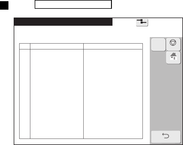
5-5 ●Confirm the registered software
View software version [Ready ]
No
01
02
03
04
05
06
07
08
09
10
11
12
13
14
15
Basic software
Controller software
Print controller software M
Print controller software S
English
Software name
Version
5.4 Confirm the registered software
(1) Functions
●Displays the name and version of the registered software.
(2) Operation
Press View software version in the Maintenance menu.
1

●Checking the functions which can be performed 5-6
5.5 Checking the functions that can be performed
(1) Functions
●Checks if each function is accessible or protected.
●When protected, the administrator sets protection using the login function beforehand.
●For protected functions, the corresponding operation buttons are not displayed or the corresponding
screens cannot be entered.
●If executable functions are restricted, the names of the corresponding screens will be shaded.
Protected functions
Item Protected function name
Edit message
●Edit message
●Calendar conditions
●Substitution rules setting
●Count conditions
Select message ●Select message
Save message ●Save message
Print specifications
●Print specifications
●Various print setup
●Adjust print parameters
Print format
●Print format
●Adjust inter-character space
Maintenance
[Auxiliary functions]
●Manage messages/group
●Create user pattern
●Calibrate touch screen coordinates
●Copy data (IJP→USB)
●Copy data (USB→IJP)
●Edit standard pattern
●Edit substitution rules
●Select languages
[Environment setup]
●User environment setup
●Date/time setup
●Communication environment setup
●Touch screen setup
[Maintenance work]
●Operation management
●Excitation V update
●Circulation control
●Solenoid valve/pump test
Password setup ●Password setup
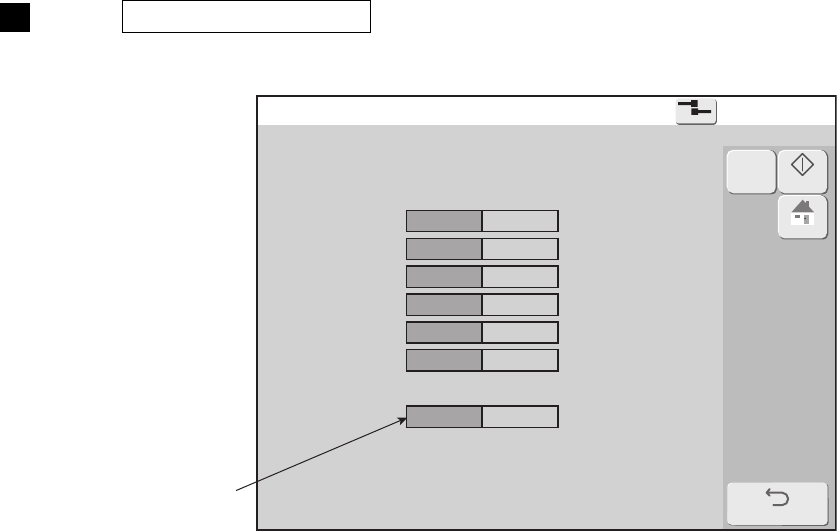
5-7 ●Checking the functions which can be performed
Password protection [Stop ]
Edit message
Select message
Save message
Print specifications
Print format
Maintenance
Password setup
access protect
access protect
access protect
access protect
access protect
access protect
access protect
(2) Operation
Press Password protection in the maintenance menu.
The Password protection screen is displayed.
1
The yellow items are
the setting contents.

●Environment setup 6-1
Environment setup menu [Stop ]
User environment
setup
Date/time setup
Communication
environment setup
Touch screen
setup
Login management
6. ENVIRONMENT SETUP
Item Contents Reference
User environment setup ● Sets the print values. 6.1
Date/time setup
● Sets the current time, calendar time and other time
information.
6.2
Communication
environment setup
● Sets the serial communication values between
external device and IJ printer.
Technical Manual
5.2
Touch screen setup ● Sets the touch screen values. 6.3
Login management
● Changes the user and sets the password for each
user.
6.4, 6.5
(2) Operation
Press Environment setup menu in the Print description screen.
The Environment setup menu screen is displayed
1
(1) Functions

6-2 ●Set the user environment
Character orientation by "Change Character Orientation" and "Change mode" combination
Change Character
Orientation
Change mode
Character orientation
Reciprocative printing
signal : OFF
Reciprocative printing
signal : ON
Reverse direction printing
OFF = forward
0:ABC(→) 1:ABC(←)
3: (→) 2: (←)
OFF = reverse
1:ABC(←) 0:ABC(→)
2: (←) 3: (→)
Normal or inverted
OFF=normal
0:ABC(→) 2: (←)
3: (→) 1:ABC(←)
OFF=Inverted
2: (←) 0:ABC(→)
1:ABC(←) 3: (→)
Character orientation
0 or 3
OFF=normal and
forward
0:ABC(→) 3: (→)
1:ABC(←) 2: (←)
OFF=inverted
and reverse
3: (→) 0:ABC(→)
2: (←) 1:ABC(←)
ABC
ABC
ABC
ABC
ABC
ABC
ABC
ABC
ABC
ABC
ABC
ABC
6.1 Set the user environment
(1) Functions
● Sets the user environment values.
signal ON While print target detect sensor signal is ON.
OFF-ON transition When print target detect sensor signal is turned ON once
Repeat print sensor mode
● Sets the conditions that print the specified number of times at the specified interval.
● Disabled when Repeat count is "0".
Change Character orientation (switching signal mode) (Optional on RX2-B)
● Sets the forward and reverse character orientation method when performing reverse direction printing.
● The "Change mode" selection menu is different depending on the "Change Character Orientation" set value.
(Example) Assume that the Change Character Orientation is "Reverse direction printing".
● If Change mode is "OFF = forward"
When the reciprocative printing signal is OFF, prints in the forward direction and when the signal is
ON, prints in the reverse direction.
● If Change mode is "OFF = reverse"
When the reciprocative printing signal is OFF, prints in the reverse direction and when the signal is
ON, prints in the forward direction.
For more detail, see "(3)change character orientation (change mode) supplement".
● When the Various print setup item "DIN print" is set to "Enable", reciprocative print signal is not
received.
1
2

●Set the user environment 6-3
(Example)
Results when print contents of
[1 2 3 4 5 6 7 8 9 0]
[ABC]
are printed in character orientation 1.
print.complete Output for a fixed time after printing is complete.
print.-in-progress Output while the IJ printer is printing.
right-justified
1 2 3 4 5 6 7 8 9 0
A BC
left-justified
1 2 3 4 5 6 7 8 9 0
ABC
● Columns with items with double width size 5 to 9 set are always printed right-justified.
● This setting functions the same as reciprocating printing reverse direction printing
● Format setup is free layout, it is printed as set the print items.
Print signal type (Optional on RX2-B)
● Sets whether the IJ printer print output signal is made print.complete or print.-in-progress.
Print Data Changeover In Progress error
● Sets whether to issue an error or not at print timing while Print data changeover is in progress.
● Error is not issued when set value is "Disabled", setup of Print data recall or Character input are
modified and overlaps print timing.
● If the print target sensor data is input before the print data changeover in communication is complete,
and error is not issued and the data prints before the changeover.
4
5
right-justified
Aligns the print position along the right margin when printing line 2 and
subsequent lines.
(The print position is different for character orientation settings 0 and 2.)
left-justified
Aligns the print position along the left margin when printing line 2 and
subsequent lines
(The print position is the same for character orientation settings 0 and 2.)
3
Reverse print
● Set for the print position at character orientation 1 and 3 setting.
Specification of Print Data Changeover In Progress error
Function
Set value of Print Data Changeover In Progress
Disabled Enabled
Print format, Character input(*1),
Calendar condition, Print specification(*2),
Print data recall
No error and changeover
Fault "Print Data
Changeover In Progress"
Count condition, Character input
(Character data in count block)
Fault "Invalid Count Data Change Timing"
Adjust print parameters, Save message,
Count reset, Operation management,
Date/time setup(Current time)
No error and changeover
User environment setup, Date/time setup
(except current time), Communication
environment setup, Excitation V update,
Print specification(Speed compensation,
Speed compensation fine control)
Fault "Invalid Data Change Timing"
● When in Ready status, user pattern can not be saved to existing pattern number.
● When in Ready status, the edit standard pattern function can not be run.
(*1) Except character data in count block.
(*2) Except Speed compensation and Speed compensation fine control.

6-4 ●Set the user environment
Char. Size menu 1
5×8, 5×7
Char. Size menu 2
9
×8, 9×7
Month 3-digit code handling (Optional on RX2-B)
● Sets the content to be printed when transmitting the Month 3-digit code by print contents transmission.
Please refer to Technical Manual "5.4 Code Tables, (7) Calendar character code" ( 5-46) for details.
Numeric
Print with numbers. (001, 002, 003…)
JAN,FEB,--
Substitute with alphabetic characters and print.
(JAN, FEB, MAR…)
Excitation V-ref. warning
● When the current ambient temperature and the standard ambient temperature (ambient temperature
when Excitation V-ref. value was updated) exceeds a certain level, the alarm "Excitation V-ref. Review"
occurs.
This setting enables/disables that function.
● Setup of enable/disable differs depending on the ink type.
Print characters one by one
● Prints only 1 character for each print target detection input.
● Prints one character at a time from the head of the print contents and returns to the head when the end is
reached.
(Printing example) Print contents [ABCDEFGH], Character orientation 0
Print target detection ↓ ↓ ↓ ↓ ↓ ↓ ↓
Print A B C G H A B
● Shows the conditions which enable the 1 character print function. When the conditions are not
satisfied, all the set print contents are printed by print material sensor input.
1 character print conditions (All the conditions must be satisfied.)
No. Condition
1 The setting item "Print characters one by one" shall be set to "Enable".
2 All print items are 1 line setting.
3 The character size of all the print items is the same.
4 No count item.
5 No bar code item.
6 Bold 1 to 4 is set.
7 Format setup is not free layout.
● When printing midway through the print contents, when any of the following occurred, printing is
repeated from the first character of the print contents.
Conditions which return the character to be printed to the start character
No. Condition
1 When the state changed (Standby→Ready, Ready→Fault, etc.)
2 When message was selected
3 When the message was changed and Apply was pressed
4
When print data was updated by external communications, external signal,
reciprocative printing signal, etc.
● The calendar is not updated between printing of the first to last characters of the print contents.
Printing is done with the date and time of the printing of the first character.
7
8
Char. Size menu
● Sets the size of the characters used.
● The following can be set:
6
QR Code printing (RX2-S only)
● The direction of the print of the QR code / Micro QR code is set. Please refer to Technical Manual
"9. APPENDIX Barcode, 2-dimensional code" ( 9-4) for details.
9
10

●Set the user environment 6-5
User environment setup [Stop ]
Repeat print sensor mode
Change Character orientation
Change mode
Reverse print
Print signal type
Print data changeover error
Char. Size menu 1
Char. Size menu 2
Excitation V-ref. warning
Reverse direction printing
OFF-ON transition
signal ON
left-justified
right-justified
print. -in-progress
print. complete
Enable
Disable
Disable
Enable
User environment setup [Stop ]
Print characters one by one
QR Code printing
Month 3-digit code handling
Enable
Disable
(2nd screen)
Normal
180-degree rotation
JAN, FEB, --
Numeric
(2) Operation
Press User environment setup in the environment setup menu.
1
Change mode
Character
orientation
Reciprocative printing signal
OFF ON
OFF = forward
0:ABC(→)
1:ABC(←)
2: (←)
3: (→)
OFF=reverse
0:ABC(→)
1:ABC(←)
2: (←)
3: (→)
(3) Change character orientation (Change mode) supplement
● The character orientation at reciprocative printing signal input is different depending on the "Change
Character orientation" and "Change mode" set values. See the table below.
ABC
ABC
ABC
ABC
Reciprocative printing signal and character orientation
(When "Change Character orientation" = "Reverse direction printing")
Order of printing
Order of printing
Order of printing
Order of printing
Order of printing
Order of printing
Order of printing
Order of printing

6-6 ●Set the user environment
Change mode
Character
orientation
Reciprocative printing signal
OFF ON
OFF=normal and
forward
0:ABC(→)
3: (→)
2: (←)
1:ABC(←)
OFF=inverted and
reverse
0:ABC(→)
3: (→)
2: (←)
1:ABC(←)
Change mode
Character
orientation
Reciprocative printing signal
OFF ON
OFF=normal
0:ABC(→)
2: (←)
1:ABC(←)
3: (→)
OFF=inverted
0:ABC(→)
2: (←)
1:ABC(←)
3: (→)
ABC
ABC
ABC
ABC
ABC
ABC
ABC
ABC
Reciprocative printing signal and Character orientation
(When "Change Character Orientation" = "Normal and inverted")
Reciprocative printing signal and Character orientation
(When "Change Character Orientation" = "Character orientation 0 or 3")
Order of printing
Order of printing
Order of printing
Order of printing
Order of printing
Order of printing
Order of printing
Order of printing
Order of printing
Order of printing
Order of printing
Order of printing
Order of printing
Order of printing
Order of printing
Order of printing

●Set the user environment 6-7
Change Character Orientation : "Character orientation 0 or 3"
Change mode : "OFF = normal and forward"
(Example) Examples of printing "ABC" onto trapezoidal print material
Change Character Orientation : "Reverse direction printing"
Change mode : "OFF = forward"
Change Character Orientation : "Normal or inverted"
Change mode : "OFF = normal"
1
2
3
● Operation examples
A B C
A B C
A B C
A B C
A B C
A B C
order of printing
order of printing
order of printing
order of printing
order of printing
order of printing
Direction of transport
Direction of transport
Reciprocative
printing signal : OFF
Reciprocative
printing signal : ON
Reciprocative
printing signal : OFF
order of printing
order of printing
order of printing
order of printing
order of printing
order of printing
A B C
A B C
A B C
A B C
A B C
A B C
Direction of transport
Direction of transport
Reciprocative
printing signal : OFF
Reciprocative
printing signal : ON
Reciprocative
printing signal : OFF
A B C
A B C
A B C
A B C
A B C
A B C
order of printingorder of printing order of printing
order of printingorder of printing order of printing
Reciprocative
printing signal : OFF
Reciprocative
printing signal : ON
Reciprocative
printing signal : OFF
Direction of transport
Direction of transport
Reciprocative
printing signal : OFF
Reciprocative
printing signal : ON
Reciprocative
printing signal : OFF

6-8 ●Sets the date and time
24-hour clock 00:00 to 23:59.
12-hour clock
A.M. 00:00 to 11:59
P.M. 00:00 to 11:59
6.2 Set the date and time
(1) Functions
● Sets the date and time values.
2
Setting item Contents Default
Current time ● Changes the current time (clock function). -
Calendar time control
● Sets whether the calendar time is the same as the current
time or is stopped.
same as
current time
Calendar time
● Sets the calendar time
● Calendar character will be printed based on "calendar
time".
● This can be set only when Calendar time control is "clock
stop".
-
Clock system
● Sets 24-hour clock or 12-hour clock.
24-hour
clock
same as current
time
● Makes the time of "Clock"
displayed at the upper right-hand
corner of the screen the calendar
time.
clock stop
● Makes an arbitrarily set time the
calendar time.
● The "Clock" (current time) at the
upper right-hand corner of the
screen is not stopped.
● A time ahead of the current time
cannot be set.
(Note) When setting the substitution rules to year, select "clock stop" and do not set the past year
instead of the current year. When set, a space is substituted for year.

●Sets the date and time 6-9
Date/time setup [Stop ]
Current time
Calendar time control
Calendar time
Clock system
clock stop
24-hour clock
same as current time
(year) (month) (day)
(hour) (minute) (second)
(year)
(month) (day)
(hour) (minute) (second)
12-hour clock
Press OK to apply the date/time setup.
The current time affects the clock display only
when changes are made.
Calendar character will be printed based on "calendar time".
(2) Operation
Press Date/time setup in the environment setup menu.
1

6-10 ●Set up the touch screen
YYYY. MM. DD Display in year.month.day order
DD. MM. YYYY Display in day.month.year order
MM. DD. YYYY Display in month.day.year order
ABC ABC layout
QWERTY Layout generally used with PC, etc.
OFF in 3 min.
Touch screen is turned off if there is
no panel input within 3 minutes.
OFF in 30 min.
Touch screen is turned off if there is
no panel input within 30 minutes.
Always on Always on
Setting item Contents Default
Display
● Specifies the time the touch screen is turned on.
[Note] When turn "OFF in 30 min." and "Always on" were
set, the brightness will decrease as the on time
accumulates.
OFF in 3 min.
Keyboard layout
● Changes the keyboard layout.
ABC
Icon display ● For some buttons, icon display or icon hide is set. Enable
Clock display format
● Selects the date format of the clock (current time)
displayed at the upper right-hand corner of the screen.
● This can be set only when Calendar time control is "clock
stop".
YYYY. MM. DD
Confirmation
window for Manual
Control Menu
●When the Startup and Shutdown button or a
button in the Manual Control menu was pressed,
confirmation message display or nondisplay is set.
However, a confirmation message is never displayed even
if the Start Printing button in the Manual Control menu is
pressed.
Display
Arabic input method
● Sets the direction of cursor movement when in Arabic
input mode.
To the left
6.3 Set up the touch screen
(1) Functions
● Sets the touch screen environment values.
Display Displays a confirmation window.
Non display
Does not display a confirmation
window.
ABCDEFGH I J
KLMNOPQRST
UVWXYZ
ABC layout
QWE R T Y U I O P
ASDFGHJKL
ZXCVBNM
QWERTY layout

●Set up the touch screen 6-11
Touch screen setup [Stop ]
Display
Keyboard layout
ICON Display
Clock display format
Confirmation window for Manual Control Menu
Arabic input method
OFF in 3 min.
ABC
QWERTY
YYYY.MM.DD
Non display
Display
Disable
Enable
to the right
to the left
(2) Operation
Press Touch screen setup in the environment setup menu.
1

6-12 ●Changing the user
Login management menu [Stop ]
Login history Select login user Password setup
User conditions
setup
Create new User ID
Using environment
setup
Delete User ID
Select login user [Stop ]
Current user ID : user9
6.4 Changing the user
(1) Functions
● Logs in again as a different user from currently logged in user.
● When logging in, selects the user and inputs the password.
● The administrator defines the user name and password and password protection setting in advance.
The password protection setting can be changed for each user beforehand. See the Technical Manual.
● When the administrator sets the login procedure necessary at power-on, the login user is selected at
power-on.
● The login history for the last 30 times is displayed on the login history screen.
(2) Operation
Press Login management in the environment setup menu.
The Login management menu is displayed.
1
Press Select login user .
The Select login user screen is displayed.
2
Displays the
history of
logged in
users.
Select login
user
Sets the password.
However, it is not
displayed when
authorization is not
given from the
administrator.
The user ID currently
logged in is displayed.
The saved user
name is displayed.
Conditions
setup
New user ID
create
Environment setup

●Changing the user 6-13
Select login user [Stop ]
Current user ID : user9
Login history
Login history
[Stop ]
user name
Date / time
Press user name user2 .
A password input window opens.
3
Enter the password of user name "user2", and press Enter .
Logs in again using user name "user2" and the touch screen returns to the Login management menu.
4
Press Login history in the Login management menu.
A history of logged in users is displayed.
5
Inputs the password
of user name "user2".
Enter
ID No. user name
Can be sorted in
ascending or
descending order.

6-14 ●Setting password for each user
Password setup [Stop ]
Old password
New password
New password reentry
Login management menu [Stop ]
Login history Select login user Password setup
6.5 Setting password for each user
(1) Functions
● User sets their own password.
● However, when the user was defined by the administrator, and the password setting is protected, the password
change screen is not displayed.
● A password must be entered when logging in.
● Make the password 12 characters or less.
Press Login management in the environment setup menu.
The Login management menu is displayed.
1
Press Password setup .
The Password setup screen is displayed.
2
Enter "Old password", "New password", and "New password reentry".
3
Press OK .
4
Displays the
history of
logged in
users.
Select login
user
Sets the password.
However, it is not
displayed when
authorization is not
given from the
administrator.
Input the old password.
Not displayed when the
password is not set.
Input the new password.
OK
(2) Operation
Please change the password periodically.

●Auxiliary functions 7-1
Aux. function menu [Stop ]
Manage messages /
Group
Create user
pattern
Calibrate touch
screen coordinates
Copy data
Copy data
Edit Standard
pattern
Edit substitution
rule
Select Languages
7 AUXILIARY FUNCTIONS
Item Contents Reference
Manage messages
●Performs message name change, deletion, save number
change, and group change of saved messages.
7.1
Manage group
●Performs group name change, group deletion and group
number change of group which classifies and manages mes-
sages.
7.2
Create user pattern ●Creates and edits user patterns (saved characters). 7.3
Calibrate touch screen
coordinates
●Corrects touch screen and screen coordinate position offset. 7.4
Copy data (IJP→USB) ●Backs up message and user pattern to USB. 7.5
Copy data (USB→IJP) ●Copies backed up data to IJ printer. 7.5
Edit standard pattern ●Edits standard patterns. 7.6
Edit substitution rules ●Edits calendar substitution rules. 7.7
Selecting languages ●Changes the display language. 7.8
(2) Operation
Press Auxiliary function in the Print description screen.
The Auxiliary function menu screen is displayed
1
(1) Functions

7-2 ●Manage messages
[Stop ]
Message name [ ]
Group No. Group name
[ ]
[ ]
Message name Message name
Multi
ple
Area
Nor-
mal
7.1 Manage messages
7.1.1 Managing stored messages
(1) Functions
(2) Operation
Press Manage messages / Group in the auxiliary functions menu.
The Manage messages screen is displayed.
● Only the RX2-S displays a preview. (Preview is not displayed on the following screens.)
11
2
Switch the selection method of the objective message.
3
After selecting the message name of the objective message, press
Change message name , Delete Stored message , Change message number , or
Change group .
The screen of each function is displayed.
Group
Sort
Switches the message selection method.
Search conditions
Select page
Display All
Details , Simple list
Manage group
Message management functions
input
Message management functions
Item Contents Reference
Change message name ●Changes the message name of stored messages. 7.1.2
Delete Stored message
●Deletes stored messages.
7.1.3
Change message number ●Changes the stored number of stored messages. 7.1.4
Change group ●Changes the group of stored messages. 7.1.5
Preview (RX2-S only)
●The print image of the registered print data can be
checked.
7.1.6
Message selection methods
Item Contents
Normal ●One message can be selected.
Multiple
●Multiple messages can be selected.
Area
●Two items in the message name list can be specified and the messages
within that area can be selected.
●For “Multiple” and “Area”, the Change message name and Change message number functions cannot be started.
●Do not turn off the printer during the Message management procedure.

●Manage messages 7-3
Manage messages [Stop ]
Message name [ ]
Group No. Group name
No
Message name
No
Message name
Nor-
mal
Area
Multi
ple
Manage messages [Stop ]
Message name [ ]
Group No. Group name
No
Message name
No
Message name
Nor-
mal
Multi
ple
Area
Normal
See the previous item for a screen example.
Multiple
Area
(3) Message selection method
1
3
2
Multiple
The message of an
arbitrary position can
be selected.
The Delete Stored message and Change group functions can be started.
The Delete Stored message and Change group functions can be started.
Area
The beginning and
end can be specified
and the messages in
that area can be
selected.

7-4 ●Manage messages
[Stop ]
Message name [ ]
Group No. Group name
No
Message name
No
Message name
Multi
ple
Area
Nor-
mal
Change message name [Stop ]
Current message name
New message name
7.1.2 Changing the message name
(1) Functions
●Changes the message name of a saved message.
(2) Operation
The Manage messages screen is displayed.
1
Set Normal selection mode and select the message.
2
Press Change message name .
The Change message name screen is displayed.
3
Press New message name .
A keyboard is displayed.
4
Input the new message name and press Enter .
5
Press OK .
The message name is changed.
Normal
Change message name
New message name
OK

●Manage messages 7-5
[Stop ]
Message name [ ]
Group No. Group name
No
Message name
No
Message name
Multi
ple
Area
Nor-
mal
Delete Stored Message Confirmation
Print data " " will be deleted.
7.1.3 Deleting stored messages
(1) Functions
●Deletes stored messages.
(2) Operation
The Manage messages screen is displayed.
1
Select the message.
2
Press Delete Stored message .
A Delete Saved Message Confirmation message is displayed.
3
Press OK .
The message is deleted.
Switches the message selection method.
Delete Stored message
OK
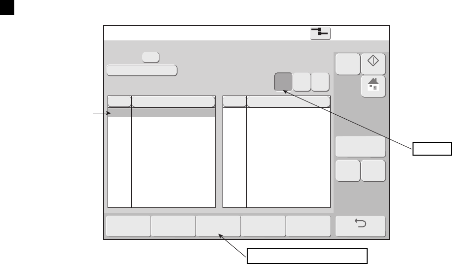
7-6 ●Manage messages
[Stop ]
Message name [ ]
Group No. Group name
No
Message name
No
Message name
Multi
ple
Area
Nor-
mal
7.1.4 Changing message number
(1) Functions
●Changes the stored number of a stored message.
●Specifies two messages and exchanges stored numbers.
● Group number is assigned to a message name.
(2) Operation
The Manage messages screen is displayed.
1
Set Normal selection mode and select the message name.
Normal
Change message number
Selects the message
whose saved number
is to be changed.

●Manage messages 7-7
Manage messages [Stop ]
Message name [ ]
Group No.
Group name [ ]
[ ]
Select the move destination
Search condition
No
Message name
No
Message name
Nor-
mal
2
[Stop ]
Message name [ ]
Group No. Group name
Select the move destination.
No
Message name
No
Message name
Nor-
mal
Select the first message and press Change message number .
The screen that selects the 2nd message is displayed.
At this time, all the messages are displayed.
To select a number without a message saved, press Free number .
All the numbers are displayed.
Free number
1st message
Selects the
2nd message.

7-8 ●Manage messages
3
Manage messages [Stop ]
Message name [ ]
Group No.
Group name [ ]
[ ]
Tow message number will be swapped.
Search condition
No
Message name
No
Message name
Nor-
mal
[Stop ]
Message name [ ]
Group No. Group name
No
Message name
No
Message name
Multi
ple
Area
Nor-
mal
Select the 2nd message.
4
Press OK .
The message stored number is changed.
1st message
2nd message
OK

●Manage messages 7-9
2
[Stop ]
Message name [ ]
Group No. Group name
No
Message name
No
Message name
Multi
ple
Area
Nor-
mal
Group Group name
7.1.5 Changing the group to which a message belongs
(1) Functions
●Changes the group to which a stored message belongs.
(2) Operation
The Manage messages screen is displayed.
1
Select the message.
2
Press Change group .
A group list window opens.
3
Specify the group.
The specified group is displayed in yellow.
4
Press OK .
The group is changed.
Switches the message selection method.
Change group
Group after change
Group before change
OK

7-10 ●Manage messages
Multi
ple
Area
Nor
mal
Manage messages
2015.07.07 12:45
[Stop ]
Message name[ ]
Group No.
Group name
[ ]
Search condition
No
Message name
No
Message name
Select message [Stop ]
Message name[ ]
Group No.
Group name
[ ]
Search condition
2015.07.07 12:45
7.1.6 Checking the print image of registered print data (RX2-S only)
(1) Functions
●The print image of registered print data can be checked.
●The print content currently being printed is not affected.
(2) Operation
The Manage messages screen is displayed.
1
Set Normal selection mode and select the message.
2
Press Preview .
The print image of the selected print data is displayed.
Selects the print data
whose print image is
to be displayed.
Preview

●Manage group 7-11
Manage group [Stop ]
Message name [ ]
No
Group name
No
Group name
Multi
ple
Area
Nor-
mal
(2) Operation
1
7.2 Manage group
7.2.1 Manage group
(1) Functions
Message management functions
Item Contents Reference
Change/create group name
●Changes a group name.
●Inputs a new group name.
7.2.2
Delete group
●Deletes a group and the messages belonging to that group.
7.2.3
Change group number
●Changes the group number.
●At messages belonging to that group, the group number is
changed and the group name is not changed
7.2.4
Group selection methods
Item Contents
Normal ●One group can be selected.
Multiple
●Multiple groups can be selected.
Area
●Two items of the group list can be specified and the groups within that area
can be selected.
● For “Multiple” and “Area”, the Change/create group name and Change group number functions cannot be
started.
1
Press Manage group in the Manage messages screen.
The Manage group screen is displayed.
2
Switch the selection method of the objective group.
3
After selecting the objective group, press Change/create group name ,
Delete group , or Change group number .
The screen of each function is displayed.
Switches the message selection method.
Select page
Manage messages
Each function of group management

7-12 ●Manage group
Manage group [Stop ]
Message name [ ]
No
Group name
No
Group name
Multi
ple
Area
Nor-
mal
Manage group [Stop ]
Current group name
New group name
7.2.2 Change group name
(1) Functions
●Changes a group name.
●Inputs a new group name.
(2) Operation
The Manage group screen is displayed.
1
Set the Normal selection mode and select the group.
2
Press Change/create group name .
Change group name screen is displayed.
3
Press New group name .
A keyboard is displayed.
4
Input the new group name and press Enter .
A keyboard is displayed.
5
Press OK .
The group name is changed.
Normal
Change/create group name
OK
New group name

●Manage group 7-13
Manage group [Stop ]
Message name [ ]
No
Group name
No
Group name
Multi
ple
Area
Nor-
mal
Delete Stored Group Confirmation
Group " " will be deleted.
Also, all messages that belong to the group will be deleted.
7.2.3 Delete a stored group
(1) Functions
●Deletes a group and the messages belonging to that group.
(2) Operation
The Manage group screen is displayed.
1
Select a group.
2
Press Delete group .
A Delete Stored Group Confirmation message is displayed.
3
Press OK .
The group and the messages belonging to that group are deleted.
Switches the message selection method.
Delete group
OK

7-14 ●Manage group
Manage group [Stop ]
Message name [ ]
Group name Group name
Multi
ple
Area
Nor-
mal
Manage group [Stop ]
Message name [ ]
No
Group name
No
Group name
Nor-
mal
Select the move destination.
7.2.4 Change group number
(1) Functions
●Changes a group number.
●Specifies 2 groups and exchanges the group numbers.
●At the messages belonging to that group, the group number is changed and the group name is not changed.
(2) Operation
The Manage group screen is displayed.
1
Set Normal selection mode and select a group.
2
Select the 1st group and press Change group number .
The screen that selects the 2nd group is displayed.
Normal
Change group number
Selects the group whose
saved number is to be
changed.
1st group
Selects the 2nd group.

●Manage group 7-15
3
Manage group [Stop ]
Message name [ ]
No
Group name
No
Group name
Nor-
mal
Two group numbers will be swapped.
Manage group [Stop ]
Message name [ ]
No
Group name
No
Group name
Multi
ple
Area
Nor-
mal
Select the 2nd group.
4
Press OK .
The saved number of the group is changed.
1st group
2nd group.
OK

7-16 ●Creating a user pattern
Create user pattern [Stop ]
Pattern [ ]
Horizontal dot
Dot matrix
Inter-char. space
Fixed
Free
(2) Operation
1
7.3 Creating a user pattern
7.3.1 Creating and saving user pattern
(1) Functions
●Creates a user pattern.
●Fixed size decides the horizontal dots and vertical dots according to the dot matrix.
●Free size allows creation of an arbitrarily sized pattern within horizontal 320 dots x vertical 32 dots.
●Shows the number of characters which can be created.
RX2-B RX2-S
Fixed size 50 messages (each dot matrix) 200 messages (each dot matrix)
Free size
- 50 messages
1
Press Create user pattern in the auxiliary functions menu.
The Create user pattern screen is displayed.
The 2 red frames display the same area.
Dot pattern creation area
Dot matrix
Inter-char. space

●Creating a user pattern 7-17
2
Create user pattern [Stop ]
Pattern [ ]
Horizontal dot
Dot matrix
Inter-char. space
Fixed
Free
Create user pattern [Stop ]
Pattern
Pattern size
Hor. 16
Vert. 16
Cursor
position
Hor. 1
Vert. 1
Set the dot matrix and inter-character space.
3
Press Create/Edit .
The Create/Edit screen is displayed.
Create/Edit
Changes the display
magnification
(X1, X2, X4).

7-18 ●Creating a user pattern
4
Create user pattern [Stop ]
Pattern
Pattern size
Hor. 16
Vert. 16
Cursor
position
Hor. 1
Vert. 1
Zoom
Create user pattern [Stop ]
Pattern
Pattern size
Hor. 16
Vert. 16
Cursor
position
Hor. 8
Vert. 3
Set Zoom and change the display magnification of the dot pattern creation area.
The display magnification of the dot pattern creation area changes.
5
Create a pattern at the dot pattern creation area. When touched directly, the dot
shading is reversed.
Scroll up
8 dots
1 dot
Scroll down
1 dot
8 dots
Clears the
pattern dots
Save
When a dot was
reversed by
touching it directly,
make the display
magnification
quadruple.
Scroll rigth
> 1 dot
>> 8 dots
Draws a graphic. (See 7.3.3.)
Scroll left
<< 8 dots
< 1 dot
Dot shading of
touched position
is reversed.
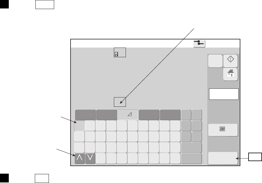
●Creating a user pattern 7-19
6
Create user pattern [Stop ]
Pattern
Dot matrix
Stored destination
pattern [000]
Press Save .
The save screen is displayed.
7
Press OK .
The pattern is saved.
When the save destination is specified the saved destination code
and pattern are displayed.
Touch the position
on the keyboard to
be saved.
Press to display
the next screen.
OK

7-20 ●Creating a user pattern
Create user pattern [Stop ]
Pattern
Pattern size
Hor. 16
Vert. 16
Cursor
position
Hor. 1
Vert. 1
Create user pattern [Stop ]
Pattern
Dot matrix
Space
etc.
7.3.2 Selecting a user pattern
(1) Functions
●Selects a saved user pattern at the “Create user pattern” screen.
(2) Operation
The Create user pattern screen or Create/edit screen is displayed.
1
Press Select .
The select screen is displayed.
2
Select the character from user pattern, letters, numbers, and symbols, and press
OK .
The pattern is selected.
Select
OK
Selects the character
to be selected.
Selects the kind
of character.

●Creating a user pattern 7-21
Create user pattern [Stop ]
Pattern
Pattern size
Hor. 16
Vert. 16
Cursor
position
Hor. 1
Vert. 1
Decide the position and press [Start].
7.3.3 Editing a pattern
(1) Functions
Name Function
Duplicate, Paste ●Duplicates the pattern of the selected range and pastes it to an arbitrary position.
Move
●Moves the pattern of the selected range.
Clear area ●Clears the pattern of the selected area.
Invert ●Inverts the pattern of the selected area.
Rectangle ●Draws a rectangle at the selected position.
Rectangle fill ●Draws a rectangle at the selected positions and fills its interior.
Paste pattern
(When editing free size)
●Duplicates the user pattern, pattern of alphabetic, numeric or symbol and pastes
it to an arbitrary position.
(2) Operation
The Create/Edit screen is displayed.
1
Press Rectangle .
The screen that selects the start point is displayed.
2
Touch the point from which drawing of the rectangle is to start.
The X mark moves to the touched position.
3
Press Start .
The start position is indicated by a red X.
The screen that specifies the end point is displayed.
Rectangle
Start

7-22 ●Creating a user pattern
4
Create user pattern [Stop ]
Pattern
Pattern size
Hor. 16
Vert. 16
Cursor
position
Hor. 16
Vert. 16
Zoom
After completing the check, press [Apply].
Create user pattern [Stop ]
Pattern
Pattern size
Hor. 16
Vert. 16
Cursor
position
Hor. 16
Vert. 16
Zoom
Decide the position and press [End].
Touch the point at which drawing of the rectangle is to end.
The X mark moves to the touched position.
5
Press End .
The Area of the rectangle with the start position and end position at opposing corners is displayed in red.
The screen that selects the end point is displayed.
End position
Start position
End
Apply

●Creating a user pattern 7-23
6
Create user pattern [Stop ]
Pattern
Pattern size
Hor. 16
Vert. 16
Cursor
position
Hor. 16
Vert. 16
Press Apply .
A rectangle pattern is drawn.

7-24 ●Creating a user pattern
Create user pattern [Stop ]
Pattern
Horizontal dot
Vertical size 1 32
Horizontal size 1 320
Free
Fixed
Create user pattern [Stop ]
Pattern
Horizontal dot
Vertical size 1 32
Horizontal size 1 320
Free
Fixed
7.3.4 Creating a user pattern of a free size
(1) Functions
●Creates a user pattern of an arbitrary size.
●The maximum size is horizontal 320 dots x vertical 32 dots.
(2) Operation
The Create user pattern screen is displayed.
1
Select Horizontal dot “Free”.
A free size Create user pattern screen is displayed.
2
Input the vertical dot size and horizontal dot size.
3
Press Create/Edit .
The Create/Edit screen is displayed.
The 2 red frames display the same area.
Vertical size
Horizontal size
Create/Edit

●Creating a user pattern 7-25
4
Create user pattern [Stop ]
Pattern
Pattern size
Hor. 32
Vert. 16
Cursor
position
Hor. 9
Vert. 12
Create user pattern [Stop ]
Pattern
Dot matrix Free
Stored destination
pattern [002]
Create a pattern at the dot pattern creation area. When touched directly, the dot is
inverted.
5
Press Save .
The save screen is displayed.
6
Press OK .
The pattern is saved.
Scroll up
8 dots
1 dot
Scroll down
1 dot
8 dots
Clears the dots of
the pattern.
Save
When a dot was
reversed by
touching it directly,
make the display
magnification
quadruple.
Scroll rigth
> 1 dot
>> 8 dots
Draws a graphic. (See 7.3.3.)
Scroll left
<< 8 dots
< 1 dot
Inverts the dot
of the touched
position.
When the save
destination is
specified, the
save destination
code and pattern
are displayed.
Touch the position
on the keyboard to
be saved.
Press to display
the next screen.
OK

7-26 ●Creating a user pattern
Create user pattern [Stop ]
Pattern
Dot matrix
Space
etc.
7.3.5 Selecting a bitmap file(BMP)
(1) Functions
●The bitmap file stored in the USB memory is called up as a user pattern.
●This can be called up by the select bitmap data screen and pattern paste screen of the free size pattern being
edited.
●Use the following conditions to create the bitmap file.
●1 pixel in the bitmap corresponds to 1 dot in the user pattern.
(2) Operation
Conditions of bit map file
Item Essential conditions
Size Width 1-320 pixels x Height 1-32 pixels
Color Monochrome (Monochrome bitmap)
File name ********.bmp (********must be within 8 digit alphanumeric or less)
1
Create a "BITMAP" folder directory under USB memory, then copy the bitmap file
created earlier.
2
Insert the USB memory in the IJP.
3
Press Create user pattern and Select next in the auxiliary function menu.
The select screen is displayed.
Select bitmap
data

●Creating a user pattern 7-27
4
No File name
B_FILE1
B_FILE2
B_FILE3
B_FILE4
B_FILE5
B_FILE6
B_FILE7
B_FILE8
B_FILE9
B_FILE10
B_FILE11
B_FILE12
B_FILE13
B_FILE14
B_FILE15
No File name
B_FILE16
B_FILE17
B_FILE18
B_FILE19
B_FILE20
Select bitmap data [Stop ]
Create user pattern [Stop ]
Pattern
Dot matrix
Space
etc.
Press Select bitmap data .
OK
Select a file from the list of bitmap file
5
Select any file name from the list of bitmap file on the screen.
Press OK (Maximum of 30 file names is displayed).
The display returns to the Create user pattern screen.
OK
6
Press OK on the select screen.
The pattern is selected.
Bitmap image which has
been selected as a pattern is
displayed

7-28 ●Touch screen coordinate correction
Touch screen coord. [Stop ]
Carefully touch the intersection of
the crosshairs.
Touch Screen Coordinate Correction
Touch screen coordinate correction will be applied.
To return to the previous setting, press [Cancel].
7.4 Touch screen coordinate correction
(1) Functions
●Corrects touch screen and screen coordinate position offset.
(2) Operation
1
Press Calibrate touch screen coordinates in the auxiliary functions menu.
The Touch screen coord. screen is displayed.
2
Press the + at the top left and bottom right of the screen until the Touch Screen
Coordinate Correction message is displayed.
The Touch Screen Coordinate Correction message is displayed.
3
Press OK .
The coordinates are corrected and the touch screen returns to the auxiliary functions menu.

●Backing up data to USB memory 7-29
Aux. function menu [Stop ]
Manage messages /
Group
Create user
pattern
Calibrate touch
screen coordinates
Copy data
Copy data
Edit Standard
pattern
Edit substitution
rule
Select Languages
●One USB memory can backup the data of multiple IJ printers.
●The same folder is created as the serial number in the USB memory.
●When copying backed up data from the USB memory to the IJ printer, select the folder to be copied.
●One USB memory can store the data for up to 100 IJ printers. However, the data size cannot exceed the
capacity of the USB memory.
●Use the auxiliary function menu to remove and insert the USB memory.
●Do not often repeatedly remove and insert the USB memory.
●When data copying standard patterns, start the copy data function in the stopped state.
7.5 Backing up data to USB memory
7.5.1 Copy data all at once
(1) Functions
●Backs up print data and user patterns to USB memory.
●Backed up data can be copied to an IJ printer.
●When copying to an IJ printer, the type of data can be selected.
Data type Contents
Print data
●Includes the print description, print format, and print specifications set contents.
●Saved print data is the backup target. Print target data is not a target.
●When backing up print target data, save the data and back it up as saved print data.
Standard
characters
●Includes all dot matrix standard character patterns.
User pattern
●Includes all dot matrix saved characters.
1
Insert the USB memory.
(2) Backup operation
The auxiliary function menu is displayed.
● Use a USB Memory with interface 2.0/1.1 and FAT16 or FAT32 file system.
● When performing Backup operation (IJP→USB) and Data copy operation (USB→IJP),
if "USB memory error"occurs or USB cannot be recognized, format the USB on a PC.
● Please periodically back up print data and user patterns.

7-30 ●Backing up data to USB memory
2
Copy data [Stop ]
Data type
Print data
Standard pattern
User pattern
Proc. Status
Copying in progress.
Serial number
Accessing to USB memory. Don't remove USB memory.
Press Copy data (IJP→USB) .
The Backup screen is displayed and the data is written to USB memory.
After backup is complete, the screen returns to the auxiliary function menu.
3
Remove the USB memory.
Aux. function menu [Stop ]
Manage messages /
Group
Create user
pattern
Calibrate touch
screen coordinates
Copy data
Copy data
Edit Standard
pattern
Edit substitution
rule
Select Languages
1
Insert the USB memory.
(3) Data copy operation
The auxiliary function menu is displayed.
Shows backup progress.

●Backing up data to USB memory 7-31
2
Copy data [Stop ]
Data type Copy data
Print data
Standard pattern
User pattern
Select the copy target and then press <Start copy>.
Serial number
Folder to be copied
Enable
Enable
Enable
Disable
Disable
Disable
Proc. Status
Copy data [Stop ]
Copying in progress.
Serial number
Folder to be copied
Data type Copy data
Print data
Standard pattern
User pattern
Proc. Status
Enable
Enable
Enable
Disable
Disable
Disable
Accessing to USB memory. Don't remove USB memory.
Press Copy data (USB→IJP) .
The copy data screen is displayed.
3
Select the folder (serial number) to be copied.
4
Select the type of data to be copied.
5
Press OK .
A copying in progress screen is displayed.
6
Remove the USB memory.
After data copying is complete, the screen returns to the auxiliary function menu.
Selects the type
of data to be copied.
Selects the folder
to be copied.
Start copy
Shows the data
copying progress.

7-32 ●Backing up data to USB memory
(4) Data copy operation from other models
●Data created on KX, PX, PB, PXR, RX, PH or PH(op:10.4 type LCD) can be copied to RX2.
Following operations 1 through 3 must be conducted prior to using other models' data on RX to store the
backup data of other models in the USB memory via a PC.
Note "PHC" shown below stands for Color LCD of PH(op:10.4 type LCD).
Prior operation
1. Create a "RXDAT" folder if it does not already exist in USB memory.
2. Create a new folder with the name of the printer's model name (KX, PX, PB, PXR,
PH or PHC) under the "RXDAT" folder created in 1. above.
3. KX Create a new folder and change its name to [8-digits serial number] under
"KX" folder created in 2. above.
Create a "IJPDATA" folder under the folder saved as the [8-digits serial
number] and copy every backup data file to "IJP DATA" folder.
PB Copy the backup serial number folder which is created on PB and rename
it as [8-digits number] under the "PB" folder created in 2.
PX,
PXR
Copy the backup serial number folder which is created on PX or PXR
under the "PX" or "PXR" folder created in 2.
PH,
PHC
Copy the backup serial number folder which is created on PH or PHC
under the "PH" or "PHC" folder created in 2.
USB memory
RXDAT
KX
00000000
IJPDATA
USB memory
RXDAT
PB
00000001
USB memory
RXDAT
PX
00000002
00000003
PXR
USB memory
RXDAT
PH
00000004
00000005
PHC

●Backing up data to USB memory 7-33
●Refer to "(3) Data copy operation" to copy data after data is stored in USB.
●The button is displayed in different colors by models when folder to be copied is selected.
Data to be copied Display color of the serial number
KX Blue
PX
Light green
PB
Magenta
PXR
Orange
RX/RX2
Black
PH
Cyan
PHC
Dark green
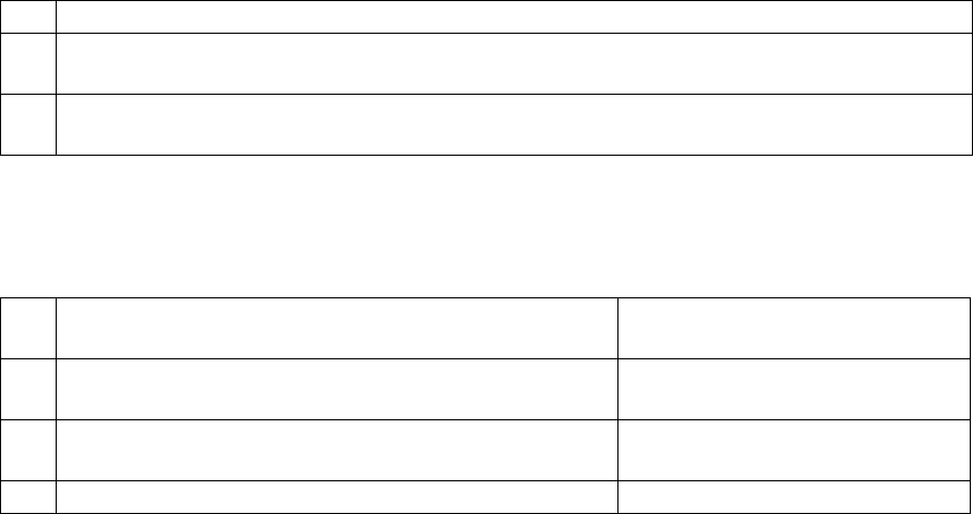
7-34 ●Backing up data to USB memory
(5) Copy data from the Upper model to the Lower model
●When the model combinations satisfy those tabulated below in Table 1, "Copy data" to the lower model is
available even if the Print data/User pattern is created on the upper model.
●Refer to "(3) Data copy operation" to copy data after data is stored in USB.
Table 1. Model combinations where Copy data is available
No. Model combinations
1
Copy data from Standard model to Basic model
[Example] Copy from 5-Lines Standard model to 3-Lines Basic model.
2
Copy data from the above-upgraded Standard model to the under-upgraded Standard model
[Example] Copy from 5-Lines Standard model to 3-Lines Standard model.
●When the Print data was created on the upper model and "Copy data" was executed to the lower model,
Print data is then classified into 3 different classifications as described in Table 2.
Table 2. Classifications of Print data
No. Classifications
Display color of Message name on
"Select message" screen
1
Print data created on the upper model can be used as is on
the lower model.
Black
2
Print data created on the upper model can be used on the
lower model by correcting a part of Print data setting.
Brown
3 Print data CANNOT be used on the lower model Red
[EXPLANATORY NOTES OF CLASSIFICATIONS(EXAMPLE)]
Classification No.1: 2-Lines Print data created on 4-Lines machine can be used as is on the 2-Lines machine.
Classification No.2: Print data of Free layout created on the Standard model can be used on the Basic model
by correcting the "Format Setup" to be set to [Individual setup].
Classification No.3: 4-Lines Print data created on the 4-Lines machine can NOT be used on 2-Lines machine.

●Backing up data to USB memory 7-35
Detailed explanation of Classification No.2 (Table 2)
●The conditions of Print data are described in Table 3, which can be used when a part of setting is corrected.
Table 3. Conditions with which display color of Message name changes to Brown on "Select message" screen
No. Item Conditions and corrections
1DIN print
"DIN print" is NOT available on the lower model. "DIN print" of Print
data shall be set to [Disable] instead of [Enable]
2 Ink Drop Charge Rule
The lower model is a Basic machine. "Ink Drop Charge Rule" of Print
data shall be set to [Standard (single scan/interlaced)] instead of [Mixed
single scan and interlaced] or [Dot mixed interlaced].
3 Product speed matching
The lower model is a Basic machine. "Product speed matching" of Print
data shall be set to [None] instead of [Auto]
4 Print format
The lower model is a Basic machine. "Format Setup" of Print data shall be
set to [Individual setup] instead of [Free layout].
5 Line spacing
The lower model has NO setting for "Line spacing expansion".
[Line spacing] of Print data shall be set to "2" instead of "3 or greater".
6
Ink drop use
(High-speed print)
There are some Ink drop use rates which are NOT available on the lower
model. "Ink drop use" of Print data shall be set to the configurable value.
Set to [HM] for "High-speed print".
[NOTE]
●After executing Select message, correct and confirm the Print data. And then please overwrite and use it for
printing. (Display color of Message name on "Select message" screen changes from Brown to Black.)
Detailed explanation of Classification No.3 (Table 2)
●The conditions of Print data which can NOT be used are described in Table 4 below.
Table 4. Conditions with which display color of Message name changes to Red on "Select message" screen
No. Item Conditions
1 Number of Print lines Max Line of the lower model < Line of Print data
2 Max Character size Max Character size of the lower model < Character size of Print data
3 Min Character size Min Character size of the lower model > Character size of Print data
4 Printing columns Max Printing columns of the lower model < Printing columns of Print data
5 Calendar items Max Calendar items of the lower model < Calendar items of Print data
6 Replacement items
Max Replacement items of the lower model < Number of Substitution rules
of Print data
7 Count items Max Count items of the lower model < Count items of Print data
8
Bar code/
2D code print
Bar code is set, which CANNOT be set on the lower model.
2D code print is set, which CANNOT be set on the lower model.
9
Shift code
Time count
Shift code is set, which CANNOT be set on the lower model.
Time count is set, which CANNOT be set on the lower model.
10 User pattern
The lower model is a Basic machine, and the settings of 51st onward of
User patterns (Fixed) are made.
The lower model is a Basic machine and the settings of User patterns (Free)
are made.

7-36 ●Backing up data to USB memory
Copy data [Stop ]
Data type Copy data
Print data
Standard pattern
User pattern
Select the copy target and then press [Start copy].
Serial number
Folder to be copied
Enable
Enable
Enable
Disable
Disable
Disable
Proc. Status
7.5.2 Copy data individually
(1) Functions
●Print data and User pattern which are backed-up in USB memory can be copied separately.
●When copying data, a separate copying operation is required for Print data and User pattern respectively.
●There are two (2) copy methods: “Add column to end” and “Overwrite”. “Add column to end” is to copy data
next to the number of already-registered. “Overwrite” is to copy data onto already-registered number(s).
●There are three (3) Copy source selections: “Normal”, “Multiple” and “Area”. “Normal” selects one data.
When “Overwrite” is selected as Copy method, Copy data can be made onto any number.
“Multiple” can select the print data which are NOT in consecutive numbers.
“Area” can select a plural print data which are in consecutive numbers.
In case “Multiple” or “Area” is selected, Copy data to any number is NOT available.
●When the plural print data are added to the end and the number of data goes beyond the maximum:
The empty data space is searched from the first number and the data will be copied there.
If there is NO space available, the data will NOT be copied.
●When the print data with the message name which is the same as that of already-existing message is copied to
the end, the message name will be renamed based on that of the source, replacing the last four (4) digits with
the registration number.
●Upon copying data, when Substitution rules is NOT registered, Substitution rules will be assigned at the same
number.
●Upon copying data, if Substitution rules is already registered, Substitution rules will be assigned/saved at the
empty number. The new number will be also assigned for Substitution rules of the print data.
●Upon copying data, if there is NO space available for Substitution rules, “Substitution Rules Confirmation”
will be displayed and Substitution rules for the print data will NOT be available.
(2) Individual Copy data operation for Print data
1
Insert backed-up USB memory into IJP.
2
Press Copy data (USB → IJP) .
Individual
copy
3
Select the folder (serial number) to be copied.

●Backing up data to USB memory 7-37
4
Copy individual print data [Stop ]
Select the copy print data and the copy destination.
Copy method
Free space %
Add column to end
Overwrite
Normal
Multipe Area
Message nameNo
USB
Message name
No
IJP
Copy individual print data [Stop ]
Select the copy print data and the copy destination.
Copy method
Free space %
Add column to end
Overwrite
Normal
Multipe Area
Message nameNo
USB
Message name
No
IJP
Copying in progress.
Press Individual copy .
“Copy individual print data” screen is displayed.
Select Copy
method.
Print data in
USB memory
Select how
you select
Print data.
Start copy
5
Select Copy method and press how you select Print data.
6
Select Print data to be copied from USB memory.
7
Press Start copy .
The message “Copying in progress” will be displayed.
8
Press HOME and return to Print description screen, then remove USB memory.

7-38 ●Backing up data to USB memory
Copy data [Stop ]
Data type Copy data
Print data
Standard pattern
User pattern
Select the copy target and then press [Start copy].
Serial number
Folder to be copied
Enable
Enable
Enable
Disable
Disable
Disable
Proc. Status
Copy individual print data [Stop ]
Select the copy print data and the copy destination.
Copy method
Free space %
Add column to end
Overwrite
Normal
Multipe Area
Message nameNo
USB
Message name
No
IJP
(3) Individual Copy data operation for User pattern
1
Insert USB memory into IJP.
2
Press Copy data (USB → IJP) .
Individual
copy
3
Select the folder (serial number) to be copied.
4
Press Individual copy .
“Copy individual print data” screen is displayed.
User
pattern

●Backing up data to USB memory 7-39
5
Pattern
Page No
Stored
destination
Page No.
Horizonal dot
Copy method
Dot matrix
Add column to end
Overwrite
Normal
Multipe Area
Copy individual user pattern
[Stop ]
Fixed
Free
Pattern
Page No
Stored
destination
Page No.
Horizonal dot
Copy method
Dot matrix
Add column to end
Overwrite
Normal
Multipe Area
Copy individual user pattern
[Stop ]
Fixed
Free
Copying in progress.
Press User pattern .
“Copy individual user pattern” screen is displayed.
Select Copy
method.
User pattern in
USB memory
Select how
you select
User pattern.
Start copy
6
Select Copy method and press how you select User pattern.
7
Select User pattern to be copied from USB memory.
8
Press Start copy .
The message “Copying in progress” will be displayed.
9
Press HOME and return to Print description screen, then remove USB memory.

7-40 ●Editing standard pattern
Edit standard pattern [Stop ]
Pattern [ ]
Dot matrix
Select
Edit standard pattern [Stop ]
Pattern
Dot matrix
Space
etc.
7.6 Editing standard pattern
(1) Functions
●Edits the print pattern in dot units.
●Punct. symbols are edited as patterns separate from full-width symbols.
●Pattern editing operation is the same as the user pattern creation function.
●Pattern-edited characters are displayed in blue on the keyboard.
●Create patterns while printing with the user pattern creation function. After applying the pattern design, use
the edit standard character pattern function.
●The original pattern before the change can be recovered.
(2) Operation
1
Press Edit standard pattern in the auxiliary function menu.
The Edit standard pattern screen is displayed.
2
Press Select .
The select screen is displayed.
3
Select characters to call.
Dot pattern
creation area
Dot matrix
Select
The 2 red frames display the same area.
OK
Selects the type
of character.
Selects the
character to
be selected.

●Editing standard pattern 7-41
4
Edit standard pattern [Stop ]
Pattern
Dot matrix
E
Press OK .
The pattern is selected.
5
Create a pattern at the dot pattern creation area.
When directly touched, the shading of the dot is reversed.
When a dot was reversed by touching it directly, make the display magnification quadruple.
6
Press Save .
The save message screen is displayed.
Restores the pattern
before the change.
Save
Edit

7-42 ●Editing Substitution Rules
Edit substitution rule [Stop ]
Message name [ ]
No
Subst. rule name
No
Subst. rule name
Edit substitution rule [Stop ]
Subst. rule name Digit
HourDayMonth
Day of
week
Week
number
MinuteYear
7.7 Editing Substitution Rules
(1) Functions
●Selects the substitution rule [Year], [Month], [Day], [Hour], [Minute], [Week number], and [Day of week]
and inputs and edits the selected substitution rule.
●Inputs and changes the name of the selected substitution rules.
See “4.10.3 Print by substituting a different character for the date (substitution rule)”.
(2) Operation
1
Press Edit substitution rule in the auxiliary function menu.
The Edit substitution rule screen is displayed.
2
Select the substitution rule to be edited and press OK .
The Edit substitution rule screen is displayed.
3
Select the kind [Year], [Month], [Day], [Hour], [Minute], [Week number],
[Day of week] of substitution rule, and input and edit.
4
Press Back .
The display returns to the substitution rule selection screen.
Sort
Prev.Dsp. ,
Next Dsp.
Select page
OK
Selects the
substitution
rule to be
edited.
Changes the
substitution
rule name.
Input digit
Duplicates the
previous item.
number
Substitution rule No.
Selects the substitution rule [Year], [Month], [Day], [Hour],
[Minute], [Week number], and [Day of week].

●Selecting Languages 7-43
Select language [Stop ]
Current language English
Registered language
Language1
Language2
Input mode
German
English
Local Language
Default
7.8 Selecting Languages
(1) Functions
● You can change the screen language from English to another language.
(2) Operation
The Auxiliary function menu screen is displayed.
Input mode
Set value Contents
Default ●You can input Accent marks, Greek, Russian and Arabic characters.
Local Language
●You can input Chinese characters.
(Language1 : English, Thai, Vietnamese only)
1
Press Select languages in the auxiliary functions menu.
The Select language screen is displayed.
2
Select German ,and press OK .
The display language is changed.
German
OK

8-1 ●Ink and makeup replenishment
● When replenishing the ink and makeup, changing the ink, or performing other work in
which the ink and makeup are handled, be sure not to spill the ink and makeup.
If the ink and makeup is accidentally spilled, quickly wipe it off with wiping paper, etc.
Do not close the maintenance cover until you verify that the wiped parts are
completely dry.
Since the ink and makeup vapor will collect inside the printer especially in the state in
which the ink and makeup was spilled inside the printer and was not wiped off
completely, it will cause ignition and fire.
When wiping is difficult in the energized state, perform shutdown processing with the
maintenance cover remaining open and turn off the power, then perform wiping
again.
● If leaking of the ink and makeup inside the printer was detected during printer
operation or maintenance, quickly wipe it with wiping paper, etc. and perform
shutdown processing with the maintenance cover remaining open and turn off the
power, then repair the leak.
If operation is continued when the ink and makeup is leaking, it will cause trouble
and prevent normal printing will become.
In addition, since the ink and makeup are combustible, they may cause a fire.
● The ink and makeup, their waste solution, used wiping papers and empty containers
are flammable. Waste disposal must comply with appropriate regulations.
Consult the appropriate regulatory agency for further information.
● When the ink particles are caught in a beaker during test printing, etc., use a
conductive beaker and securely connect the beaker to a ground.
In addition, be sure that the print head is not inserted into the beaker.
Since the ink particles used in printing are electrically charged, if the beaker is not
connected to a ground, the charge load will gradually increase and cause a fire.
8. INK AND MAKEUP
REPLENISHMENT
● Never pour the ink and makeup waste into a sewer, etc.
Have the ink and makeup drainage processed by an industrial waste processor as
special control industrial waste and used wiping papers and the empty container as
industrial waste.
● Do not remove, apply unreasonable force to, or bend the piping tubes unnecessarily.
Since high pressure is applied to parts of the ink and solvent inside the piping tube,
the ink and solvent may spurt out and get into your eyes and mouth or soil your
hands and clothing.
If the ink or solvent gets into your eyes or mouth, immediately rinse it out with warm
water and see a doctor.
WARNING
● Pay careful attention to the following items regarding handling of the ink and makeup:
Wear gloves and goggles so that the ink and makeup will not directly contact your
skin.
If the ink or makeup gets on your skin, wash it off with soap and warm water.
When taking the ink or makeup in and out of the bottle, be sure that the ink or
makeup does not get on the equipment and surroundings. If the ink or makeup gets
on the equipment or surroundings, immediately wipe it off with makeup.
Since the vapor pressure of the makeup is generally high, if the ambient
temperature is high such as in the summer, etc., the internal pressure will rise and
makeup could spurt out when the outside cover is removed. Therefore, when
unplugging,
●do not hold the bottle near your face
●place the can on a level surface
●open while covering the opening with a rag, etc.
CAUTION
1
2
3

●Replenishing the ink 8-2
8.1 Replenishing the ink
(1) Overview
●Replenish the ink in the ink reservoir within 60 minutes after an Ink Low warning is generated. If the ink is
not replenished, the printer will stop.
●The ink can be replenished without regard to whether the IJ printer power is ON or OFF or the printer’s
operating state.
●When the ink is replenished, the warning is automatically reset.
(2) Operation
Open the maintenance cover, pull the ink reservoir forward, and remove the cap
of the ink reservoir.
1
Remove the cap from the ink bottle and replenish the ink by pouring it into the
ink reservoir.
●Adjust the amount replenishment in accordance with the ink consumption.
Exercise care to avoid excessive replenishment.
2
Close the ink reservoir cap.
●Tighten the cap securely. The solvent component may evaporate.
3
Return the reservoir to its original position.
4
Close the maintenance cover. 5
Pull out.
Ink reservoir
Maintenance cover
Cap
Cap
Ink reservoir
Ink bottle
If ink is accidentally spilt, wipe it up promptly with wiping paper or something
similar. In addition, do not close the maintenance cover until you are sure that
the wiped portion has completely dried.
CAUTION
●When moving the reservoir, move it gently.
●Hold the reservoir and pull it forward.

8-3 ●Replenishing the makeup
8.2 Replenishing the makeup
(1) Overview
●Replenish the makeup in the makeup reservoir within 60 minutes after a makeup Low warning was
generated. If replenishment is not performed, the printer will stop.
●The makeup can be replenished without regard as to whether the IJ printer power is ON or OFF or the
printer’s operating state.
●When the makeup is replenished, the warning is automatically reset.
(2) Operation
Open the maintenance cover, pull the makeup reservoir forward, and remove the
cap of the makeup reservoir.
1
Remove the cap from the makeup bottle and replenish the ink by pouring it into
the makeup reservoir.
2
Close the makeup reservoir cap.
●Tighten the cap securely. The solvent component may evaporate.
3
Return the reservoir base to its original position.
4
Close the maintenance cover. 5
Makeup reservoir
Maintenance cover
Cap
Makeup bottle
Makeup
reservoir
●Gradually add the makeup to avoid spilling. Also, exercise care to avoid excessive replenishment.
●If the mesh filter inside the cap is soiled, take it out and clean it
If makeup is accidentally spilt, wipe it up promptly with wiping paper or some-
thing similar. In addition, do not close the maintenance cover until you are sure
that the wiped portion has completely dried.
CAUTION
Pull out.
Cap
●When moving the reservoir, move it gently.
●Hold the reservoir and pull it forward.

●Display when warning or fault was generated 9-1
Target Sensor Fault052
The print target detection signal was ON longer than
the timeout setting of Target Sensor Timer.
Cause 1. The print target detection signal ON time is too long.
2. The Target Sensor Timer setting is incorrect.
Solution 1. If the target is stopped in front of the sensor, move the target.
2. Change the Target Sensor Timer setting.
Close
Reset
9. WHEN WARNING OR FAULT
WAS GENERATED
●When an operation mistake is made and processing judgment is prompted, a confirmation message is
displayed.
●When a “Fault state” which hinders printing was generated while the liquid crystal screen
backlighting was off or when a “Warning state” which does not hinder printing but requires
maintenance was generated, a fault message or warning message is displayed in a window.
(1) When a fault was generated
9.1 Display when warning or fault was generated
●When a warning or fault was generated, a warning or fault lamp lights.
●When Clear is pressed after removing the cause, the fault state is cleared and the message is also
closed.
●When Close is pressed, the fault window is closed, but the fault state is not cleared. When Fault in
state area, the fault message is displayed again.
●However, when the fault state is already cleared, it is cleared by Close .
Operational status display lamp
Message No.
The name of the fault
message is displayed.
The description, cause,
and solution are displayed.

9-2 ●Display when warning or fault was generated
Ink Low Warning081
The ink level in the ink reservoir is low.
Cause 1. The ink reservoir is almost empty.
2. The Low Level sensor in the ink reservoir is faulty.
Solution 1. Add more ink to the ink reservoir within 60 minutes.
2. Check the Low Level sensor.
Close
Ink Jet Startup Confirmation186
The ink jet will be turned ON.
Solution To turn the ink jet ON, press <Ready>.
Close
Ready
●When Close is pressed, the warning window is closed, but the warning state is not cleared.
The warning name is displayed in the warning display area (see the figure above).
●If the warning state is cleared, the warning display is automatically closed.
(2) When warning was generated
(3) When a mistake was generated or when processing judgment is prompted
●The contents of the confirmation message are described at the place of each operation.
Message No.
The name of the warning
message is displayed.
The description, cause,
and solution are displayed.
Message No.
The name of the confirmation
message is displayed.
The description, cause,
and solution are displayed.

●On-screen message descriptions 9-3
No. Message Meaning of message Remedy
1 Ink Low Fault
The ink reservoir is almost empty and
printing will stop.
(If the ink is not added or replaced within
60 minutes after warning output, the printer
comes to a stop with the warning condition
replaced by a fault condition.)
● Add ink to the ink reservoir.
( 8.1).
2
Main Ink Tank Too
Full
The ink level in the main ink tank is too
high.
● Drain proper amount of ink
in the main ink tank.
( Technical manual
6.3, 6.13).
3
Deflection Voltage
Fault
The high-voltage power supply output
voltage is too low or too high.
● Contact your nearest local
distributor.
4
Ink replenishment
Time-out
The automatic ink refill process exceeded
the time limit.
● Contact your nearest local
distributor.
5
Ink Drop Charge
Too Low
The ink drops are poorly charged.
● Clean the gutter, deflection
electrode, and its
surroundings.
● Adjust the excitation setting
to make sure that the ink
drops are well made.
( Technical manual 6.11).
● Adjust ink pressure.
( Technical manual 6.10).
6
System operation
error C
Unexpected error occurred.
● Turn the power OFF and then
back ON after 10 seconds.
7
System operation
error M
Unexpected error occurred.
● Turn the power OFF and then
back ON after 10 seconds.
8
System operation
error S
Unexpected error occurred.
● Turn the power OFF and then
back ON after 10 seconds.
9
Deflection Voltage
Leakage
The deflection electrode voltage is too low.
● Clean and dry the deflection
electrode and nearby parts.
10
Makeup
replenishment
Time-out
The automatic makeup refill process
exceeded the time limit.
● Contact your nearest local
distributor.
11 Makeup Low Fault
The makeup reservoir is almost empty and
printing will stop.
(if replenishment is not effected within 60
minutes after warning output)
● Add the makeup to the
makeup reservoir.
( 8.2).
12
Ink Heating Unit
Temprature Too
High
The temperature of the ink heater in the
print head is too high.
The heater will be temporarily deactivated.
● Contact your nearest local
distrib
utor.
13
Multi DC Power
Supply Fan Fault
The cooling fan in the multi DC power
supply has a fault. The ink ejection will
stop and the printer will be automatically
shutdown.
● Contact your nearest local
distributor.
9.2 On-screen message descriptions
9.2.1 Fault messages
(1) Faults that invoke ink stoppage

9-4 ●On-screen message descriptions
No. Message Meaning of message Remedy
14
Charge Voltage
Too Low
The charging voltage supplied to the nozzle
drive board EZJ125 from the high-voltage
power supply unit is too low.
● Contact your nearest local
distributor.
15
Charge Voltage
Fault
The charge electrode signal is faulty.
● Check that there is no short-
circuit with another part.
16
No Ink Drop
Charge
The ink drops are not electrically charged.
● Check if the ink stream is at
about the center of the gutter.
● Clean the gutter, deflection
electrode, and its
surroundings.
● Adjust the excitation V-ref. to
make sure that the ink drops
are well made.
( Technical manual 6.11).
● Check the ink pressure.
( Technical manual 6.10).
17
Ink Heating Unit
Temperature
Sensor Fault
The temperature measured at the ink
heating unit is out of normal range.
The heater will be temporarily deactivated.
● Contact your nearest local
distributor.
18 Memory Fault C The memory data has a fault. ● Execute system setup.
19 Memory Fault op
The memory of the option board EZJ130
has a fault.
● Contact your nearest local
distributor.
20 Memory Fault M The memory data has a fault.
● Contact your nearest local
distributor.
21
Ink Drop Charge
Error
Charge control on ink drops has a fault.
No print or disordered print may occurs.
● Contact your nearest local
distributor.
22
Internal
Communication
Error S
The internal data processing error.
● Turn the power OFF and then
back ON after 10 seconds.
23
System Operation
Error S
Unexpected error occurred.
Please verify if the work is printed
correctly.
● Afer ink is stopped, turn OFF
the power of the printer.
● Contact your nearest local
distributor
24
Ink Heating
Unit Over Current
The ink heating element is shorted.
The heater will be temporarily deactivated.
● Contact your nearest local
distributor.
25
Ambient
Temperature
Sensor Fault
The ambient temperature measurement is
out of normal range.
●
Contact your nearest local
distributor.
26
Print Controller
Cooling Fan Fault
The cooling fan of the print controller area
is faulty.
● Contact your nearest local
distributor.
30 Memory Fault S The memory data has a fault.
● Contact your nearest local
distributor.
31 Pump Motor Fault Pump motor is faulty.
● Contact your nearest local
distributor.
32
Inside Temperature
Sensor Fault
The inside temperature measurement is out
of normal range.
● Contact your nearest local
distributor.
34
Ink Heating Unit
Temperature Low
The ink heater in the print head is unable to
heat the ink enough to reach the correct
operating temperature.
The heater will be temporarily deactivated.
● Contact your nearest local
distributor.
●On-screen message descriptions 9-5
(2) Faults that do not invoke ink stoppage
No. Message Meaning of message Remedy
35 Model-key fault Model-key recognition failed.
● Contact your nearest local
distributor.
37 Language key fault Language-key recognition failed.
● Contact your nearest local
distributor.
No. Message Meaning of message Remedy
35 Model-key fault Model-key recognition failed.
● Contact your nearest local
distributor.
37 Language key fault Language-key recognition failed.
● Contact your nearest local
distributor.
27
Print Data
Changeover
Error C
The print data change procedure was
incomplete.
● Check the data entered
28
Print Data
Changeover
Error M
The print data change procedure was
incomplete.
● Check the data entered
38
Free Layout
Printing Failure
The free layout printing was aborted while
the message was printing.
● Delete some print items or
decrease the setting of the ink
drop use. ( 4.8.6)
40
External
Communication
Error nnn
The serial communication port had a data
error.
● Note the error code and see
that no more error occure.
( Technical manual 5.7)
42
Ink Drop Charge
Too High
The charge sensor detects a high drop
charge.
● Clean the gutter, deflection
electrode, and its
surroundings.
● Adjust the excitation V-ref. to
make sure that the ink drops
are well made.
( Technical manual 6.11)
● Adjust the ink pressure.
● Check that the ink stream is
correctly retracted.
( Technical manual 6.10)
43
Barcode Short On
Numbers
The number of characters for the selected
barcode type is insufficient.
●Configure the number of
( 4.8.5) characters for
barcode to appropriate value.
( Technical manual 9)
44 Shutdown Fault The shutdown process failed.
●Turn the printer power OFF by
main switch.
Contact your nearest local
distributor.
45 Count Overflow
The calculation result of the count
multiplier overflowed.
● Change the count multiplier
setting.
46
Invalid Data
Change Timing
A print operation was requested while the
print data was being changed.
● Change of either data change
or print start.
47
Invalid Count Data
Change Timing
A print operation was requested while the
print data was being changed.
● Change of either data change
or print start.
48
Invalid Print S
tart
Timing
The print target detection signal for the next
target arrived during the data was being
changed.
● Change of either data change
or print start.

9-6 ●On-screen message descriptions
No. Message Meaning of message Remedy
49 Print Overlap Fault
The print target detecter signal for the next
target arrived during the print operation for
the current target.
● Increase the spacing between
products.
● If the target signal is
chattering, use sensor filter
setting. ( 4.14.1).
50
Print Head Cover
Open
The print head cover is open.
● Remove the cover and then
hit the Clear key.
● If a magnetic substance is
used to fix the cover,
it must be replaced with
nonmagnetic resin (metal).
51
Detector Position
Improper
The print target detecter signal turned OFF
before print start during printing at repeat
print setting.
● Move the print target detecter
closer to the print head.
● If the target signal is
chattering, use sensor filter
setting.
● Check the data entered.
52
Target Sensor Time
Out
The print target detecter signal was ON
longer than the timeout setting of Target
Sensor Timer.
● If the target is stopped in front
of the sensor, move the target.
● Change the Target Sensor
Timer setting.
( 4.14.1).
53
Target Spacing Too
Close
There are 5 or more print target detector
signal turned ON before print start during
printing at No repeat print setting.
● Move the print target detecter
closer to the print head.
54
Print Data
Changeover In
Progress S
A print operation was requested while the
print data was being changed.
● If the target signal is
chattering, Use Sensor filter
setting.
● Change of timing either print
data change or print start.
55
Ink Self Life
information
Replacement of ink is recommended.
● Use ink within its expiration
dae at replacement.
● Confirm ink of number on
unit information screen.
● Contact your nearest local
distributor.
56 Blank Print Items The print items are not properly set up. ● Change the print data.
57
Excessive Format
Count
A column has more than 8 print format
types (the number of lines, line spacing,
character size, character spacing, bold
charcter and bar code).
● Perform setup so that the
number of print format types
does not exceed 8.
58
Print Data
Changeover In
Progress M
A print operation was requested while the
pri
nt data was being changed.
● Change timing of either print
data change or print start.
59
Print Data
Changeover In
Progress V
A print operation was requested while the
video data was being changed.
● Adjust either the encoder
frequency or the pulse rate
division factor.
● Change timing of either print
data change or print start.
60
Communication
Buffer Fault
The print contents are not in the
communication buffer.
.● Adjust the print and
communication timing.

●On-screen message descriptions 9-7
No. Message Meaning of message Remedy
61
Makeup Self Life
information
Replacement of makeup is recommended.
● Use makeup within its
expiration date at
eplacement.
●Confirm makeup lot number
on unit information screen.
● Contact your nearest local
distributor.
62
Internal
Communication
Error C
The internal data processing error.
● Ink stop and the printer power
OFF are recommend.
Turn the printer OFF and then
back ON after 10 seconds.
63
Internal
Communication
Error M
The internal data processing error.
● Ink stop and the printer power
OFF are recommend.
Turn the printer OFF and then
back ON after 10 seconds.
9.2.2 Warning messages
No. Message Meaning of message Remedy
65
Excitation V-ref.
Review
The excitation voltage reference needs to
be updated.
● Perform the Nozzle test and
update the Excitation V-ref.
setting.
( Technical manual 6.10)
66
Viscosity Reading
Instable
The viscometer output readings fluctuated.
Setting will be temporarily switched to no
use of viscometer.
● Contact your nearest local
distributor.
67
Viscosity
Readings Out of
Range
The viscometer is defective.
Setting will be temporarily switched to no
use of viscometer.
● Contact your nearest local
distributor.
68 Ink Viscosity High The ink viscosity is above the proper level.
● The ink concentration will be
adjusted to normal level.
If print quality is still poor,
then replace ink.
( Technical manual 6.3)
69 Ink Viscosity Low Ink viscosity is below the proper level.
● The ink concentration will be
adjusted to normal level.
If print quality is still poor,
then replace ink.
( Technical manual 6.3)
71 Battery Low M
The internal battery in engine section is
low.
The latest print data and operating
information may not be saved.
● Contact your nearest local
distributor.
● Replace the internal battery
in engine section and set the
data/time. ( 6.2).
72
Calendar Content
Inaccurate
Calendar content is inaccurate due to mal-
function of the clock.
● Contact your nearest local
distributor.
● Set the date/time. ( 6.2).
-
External
Communication
Error nnn
The serial communication port had a date
error.
● Note the error code and see
that no more errors occur.
( Technical manual 5.7)

9-8 ●On-screen message descriptions
No. Message Meaning of message Remedy
80
Excitation V-ref.
Review 2
Up date the excitation voltage reference.
Print quality may become poor.
● Perform nozzle test and
update the excitation V-ref.
setting.
( Technical manual 6.11)
● Watch for the print results and
the Excitation V-ref.
Setting. for about 2 hours
after operation is started.
81 Ink Low Warning The ink level in the ink reservoir is low.
● Add ink within 60 minutes
( 8.1).
82
Makeup Low
Warning
The makeup level in the makeup reservoir
is low.
● Add the makeup within 60
minutes.
( 8.2).
83
Ink Shelf Life
Expired
Ink replacement time has come.
● Replace the ink
( Technical manual 6.3).
84
Ambient
Temperature Too
High
The ambient temperature is above the
proper level.
● Ensure that the ambient
temperature is within the
operating temperature limits.
85
Ambient
Temperature Too
Low
The ambient temperature is below the
proper level.
● Ensure that the ambient tem-
perature is within the operat-
ing temperature limits.
87 Ink Pressure High
Ink pressure is higher than the
recommended value.
● Adjust the pressure-reducing
valve to correct the pressure.
88 Battery Low C
The internal battery in controller section is
low.
● Contact your nearest local
distributor.
● Replace the internal battery
in engine section and set the
data/time. ( 6.2).
93 Ink Pressure Low
Ink pressure is lower than the
recommended value..
● Adjust the pressure-reducing
valve to correct the pressure.
95
Product Speed
Matching Error
The encoder pulse rate exceeds the
available printing speed.
● Slow the print target speed.
● Decrease N in the ink drop
use percentage (1/N).
( 4.14.1).
129 Model-key Failure Model-key recognition failed.
● Contact your nearest local
distributor.
130
Language-key
Failure
Language-key recognition failed.
● Contact your nearest local
distributor.
131 Upgrade-key Fault Upgrade-key recognition failed.
● Co
ntact your nearest local
distributor.
135
Circulation System
Cooling Fan
Fault
The cooling fan of the circulation system
area is faulty.
● Contact your nearest local
distributor.
136
Inside Temperature
Too High
The temperature inside the printer is
increasing.
● Prease confirm the ink
recovery status.
● Replace the air filter or make
the space around printer.
● Contact your nearest local
distributor.

●On-screen message descriptions 9-9
9.2.3 Other messages
No. Message Meaning of message Remedy
187
Ink Temperature
Correction Notice
The selected setup does not allow ink
temperature corrections to be made.
( P1-4)
● Contact your nearest local
distributor.
200
No Ink
Concentration
Control
The current settings have made ink
concentration control unavailable.
( P1-5)
● Contact your nearest local
distributor.
201
Print Data/Settings
Notice
Recent changes to print data and printer
settings may have been lost. In the previous
session, power was cut OFF suddenly.
● Check print contents and each
setting value.
209
Print Start up
Failure
Printer startup failed.
● Turn the printer power OFF
and then back ON after 10
seconds.
● Contact your nearest local
distributor.
210
USB Memory
Error
USB memory is not inserted. Or an error
was generated when reading USB memory.
●Insert correctly.
●Replace with a new USB
memory.

9-10 ●When checking the warning and fault generation status
2
Fault/warning log
Fault/warning log
[Stop]
No
01
02
03
04
05
06
07
08
09
10
11
12
13
14
15
Name of alarm
Date/time
9.3 When checking the warning and fault generation status
(1) Functions
●The warning or fault message generation time and contents can be viewed.
●A maximum of 90 messages can be displayed.
●When 90 messages are exceeded, the messages are closed from the oldest message.
(2) Operation
1
Press View alarm history in the Manage messages screen.
The Fault/warning screen is displayed.
Sorted from generation date.
Message No.

●Remedial action to be taken in the event of a printing failure 9-11
(*1) See the Technical Manual
No.
Printing failure
description
(phenomenon)
Probable cause Solution Reference
1
Chipped print
(minus deflection
electrode side)
Ink and foreign matter are
stuck to the gutter.
● Clean the gutter.
● Replace the recovery
filter.
6.6 (*1)
6.8 (*1)
Ink and foreign matter are
stuck to the charge and
deflection electrodes.
● Clean the charge and
deflection electrodes.
3.1.2
Ink and foreign matter are
stuck to the ink ejection port.
● Remove the ink and foreign
matter.
-
The ink stream is improperly
positioned.
● Adjust the ink stream. 6.5 (*1)
The ink pressure is too high.
● Adjust the ink pressure for
the standard value.
6.10 (*1)
The ink has deteriorated. ● Replace the ink. 6.3 (*1)
2
Chipped print
(plus deflection
electrode side)
Ink and foreign matter are
stuck to the charge and
deflection electrodes.
● Clean the charge and
deflection electrodes.
3.1.2
Ink and foreign matter are
stuck to the ink ejection port.
● Remove the ink and foreign
matter.
-
The flow within the nozzle is
restricted.
● Backwash the nozzle. 6.4 (*1)
The character height setting is
too great.
● Decrease the character
height setting.
4.14.1
The ink pressure is too low.
● Adjust the ink pressure for
the standard value.
6.10 (*1)
The ink has deteriorated. ● Replace the ink. 6.3 (*1)
3
Varying character
height
The clearance between the
print head and print target has
changed.
● Adjust the clearance
between the print head and
print target.
-
Ink and foreign matter
are stuck to the charge and
deflection electrodes.
● Clean the charge and
deflection electrodes.
3.1.2
Ink and foreign matter are
stuck to the ink ejection port.
● Remove the ink and
foreign matter.
-
The flow within the nozzle is
restricted.
● Backwa
sh the nozzle. 6.4 (*1)
The ink pressure has changed.
● Adjust the ink pressure for
the standard value.
6.10 (*1)
The ink has deteriorated. ● Replace the ink. 6.3 (*1)
1
9.4 Remedial Action to Be Taken in the Event of a Printing
Failure
● If a printing failure occurs, perform the associated remedial procedures suggested below.
● If the remedial procedures below do not achieve recovery, it is conceivable that the problem is
attributable to a PC board or circulation system failure. In such an instance, contact your nearest local
distributor.
Direction of deflection
←Chipped
(lost)
Direction of deflection
←Chipped
(lost)

9-12 ●Remedial action to be taken in the event of a printing failure
No.
Printing failure
description
(phenomenon)
Probable cause Solution Reference
4
Disordered
characters
There are water, oil, or other
deposits on the print target
surface.
● Make prints with the print
target clear of deposits.
-
The ink pressure has changed.
● Adjust the ink pressure for
the standard value.
6.10 (*1)
Ink and foreign matter are
stuck to the charge and
deflection electrodes.
● Clean the charge and
deflection electrodes.
3.1.2
The flow within the nozzle is
restricted.
● Backwash the nozzle. 6.4 (*1)
The ink has deteriorated. ● Replace the ink. 6.3 (*1)
The excitation V-ref. value is
improper.
● Adjust the excitation V-ref.. 6.11 (*1)

●Troubleshooting guide 10-1
Phenomenon Check Solution
The power does not turn
ON at the press of the Start
switch.
● Check that the main power switch is
turned ON.
● Turn ON the main power switch.
● Check that the power plug is properly
connected to a power outlet.
● Check that electrical power is supplied
to the employed power outlet.
● Turn OFF the main power switch.
Ensure that power is supplied to
the power outlet, and then
connect the power plug to the
power outlet.
● Check that Status indicator lamp is not
on when Start switch is pressed.
● Check that Start switch is pressed for
about 2 seconds.
● Ensure that Status indicator lamp
is off when pressing the Start
switch.
● Ensure that Start switch is pressed
for about 2 seconds.
Pressing a key does not
invoke its predefined
operation.
Or the key is not accepted.
● See “7.4 Touch Screen Coordinate correction”.
The calendar time is not
correctly printed.
● Check that "clock stop" is not selected
from the date/time setup screen.
See “6.2 Set the Date and Time”.
● Select the "same as current time"
option.
See “6.2 Set the Date and Time”.
The printer does not
become ready for
printing when Start up is
pressed.
● Check for an ink stream ejection from
the nozzle.
● Check whether the ejected ink stream
enters the gutter hole.
● Stop the ink ejection sequence
by pressing the Shut down .
● See the Technical Manual “6.4
How to correct ink stream bend-
ing and nozzle clogging”, and
correct the problem.
● Check if the print head are dirty.
● See “1.3 Print head cleaning”,
and perform the operation.
“Print overlap fault”
occurs frequently.
See “9. When Warning or Fault was generated”.
A fault message is
displayed.
Residual image of
characters, etc. remains on
the screen.
-
●Because of the characteristics of
the liquid crystal panel, when the
same pattern is displayed for a
long time, a residual image of the
pattern may remain. However, the
residual image will disappear with
the passage of time.
10. TROUBLESHOOTING GUIDE
If the printer does not start up normally, perform the following checks before deciding the printer is malfunctioning.
● If the above remedies do not restore the printer to normal, stop using
the printer, disconnect the power plug from the power outlet, and
contact your Hitachi distributor.
CAUTION
■ Report the following to your local source or service company:
1. TYPE-FORM (model number) IJ printer (Model RX2- )
2. SER. No. (serial number) RX2
3. Failure description In detail
4. Organization name (department and section names included), name of person in charge, and
telephone number.
* The model number and serial number are marked on the nameplate that is attached to the
right-hand side of the printer.

11-1 ●Emergency Procedures
11. EMERGENCY PROCEDURES
Press the main power switch to turn OFF the power.
● If an earthquake, fire, or other emergency arises while the printer is
operating or when its power is on, turn OFF the power by pressing the
main power switch.
Never perform this procedure except in case of an emergency.
WARNING
● Immediately after the emergency is cleared, press the main power switch to turn the power back
ON and press the Start up to initiate ink ejection.
● If the emergency lasts for 5 minutes or longer, open the print head cover and clean the orifice plate
and its surrounding parts and gutter section by pouring makeup over them.
When resuming operation, thoroughly clean the orifice plate and its surrounding parts and gutter
section by pouring makeup over them, and then initiating ink ejection.
● If the power supply is shut off by a power failure, perform the same procedure as indicated above.
In the event of a power failure
When you use the printer after power restoration, be sure to confirm the printings
and other setup data beforehand. If you find any incorrect printings or setup
data, correct it.
Note that the count update information for printing is not saved in memory.
When you use the printer after power restoration, it is necessary to set the count
update information (initial value data) again.
CAUTION
1
2
Main power switch

●Specifications 12-1
12. SPECIFICATIONS
Item
Model
RX2-SD160 RX2-BD160
Nozzle size 65μm
Max. print line number
Up to 3 lines
(OP: Up to 5 lines)
Up to 3 lines
Maximum number of print
characters
Up to 240 characters
(OP: Up to 1000 characters)
Up to 60 characters
Font
4x5 Option: V -
5x5 V V
5x7(8),9x7(8) V V
7x10 V V
10x12 V V
12x16 V V
18x24 V -
24x32 Option: V -
Character height 2-10 mm / 0.08-0.39 inches
Display & input device
WYSIWYG design; Display: TFT LCD (10.4" color), backlight provided;
Input device: Touch panel, input sound provided
Maximum print rate
(character per second)
(Excitation frequency 76.9kHz,
Font 5x5, space 1, 1line)
Up to 1,281
(OP: Up to 2,563)
Up to 854
Standard characters Alphanumeric (A-Z, a-z, 0-9), symbols (27), space : Total 90
User pattern Each dot matrix 200 patterns Each dot matrix 50 patterns
Print functions Calendar, Count, Font mixture, Passwords security, etc.
Barcode printing
code39, ITF, NW-7, EAN-13, EAN-8, UPC-A,
UPC-E, code128/EAN-128, GS1 DataBar
-
2D code printing Data Matrix , QR code, Micro QR -
Message storage capacity
300 messages
(Op: Up to 2000 messages
(depends on data content))
24 messages
Input signal
Print target detection, Rotary encoder pulse,
Printing stop, Reciprocative printing,
Remote control (Run, Stop, High-voltage ON/
OFF, Reset)
(NPN/PNP Selectable)
Print target detection, Rotary encoder pulse
(NPN/PNP Selectable),
OP:Printing stop,
Reciprocative printing,
Remote control (NPN/PNP Selectable)
Output signal
Print ready, Fault, Warning (NPN Only),
Print in progress or Print complete,
Online (NPN/PNP Selectable)
Print ready, Fault, Warning (NPN Only),
OP:Print in progress or Print complete,
Online (NPN/PNP Selectable)
Data interface RS-232C
RS-232C at baud rates selectable up to
115,200bps
Option
(RS-232C at baud rates selectable up to
115,200bps)
External memory USB for user data storage
Head cable length, angle 4m / 13.1ft, inline / 90 degrees
Operating temperature range 0-45ºC / 32-113ºF (JP-K67, JP-K69 Ink)
Humidity range 30-90% R.H. (No condensation)
Power supply
(Automatic voltage selection)
AC100-120/220-240V±10% 50/60Hz 120VA (AC Inlet)
Corrosive gas There must be no corrosive gas
Overall size
(Width x Depth x Height)
400x340x480mm / 15.7x13.4x18.9 inches
Approximate weight 25kg / 55lbs

13-1 ●Appendix
A
Actual print width . . . . . . . . . . . . . . . . . . . . . . . . . . . . . . . . . . . . . . . . . . . . . . . . . . . . . . . . . . . . . . . . . . 4-75
Add column to end. . . . . . . . . . . . . . . . . . . . . . . . . . . . . . . . . . . . . . . . . . . . . . . . . . . . . . . . . . . . . . . . . 4-17
Adjust print parameters . . . . . . . . . . . . . . . . . . . . . . . . . . . . . . . . . . . . . . . . . . . . . 3-17, 4-1, 4-5, 4-73, 5-6
Adjustment char. Condition . . . . . . . . . . . . . . . . . . . . . . . . . . . . . . . . . . . . . . . . . . . . . . . . . . . . . . . . . . 4-21
Alphabet month 3 digits (JAN, FEB, ----) . . . . . . . . . . . . . . . . . . . . . . . . . . . . . . . . . . . . . . . . . . . . . . . . 4-35
Auto encoder . . . . . . . . . . . . . . . . . . . . . . . . . . . . . . . . . . . . . . . . . . . . . . . . . . . . . . . . . . . . . . . . 4-74, 4-75
B
Bold . . . . . . . . . . . . . . . . . . . . . . . . . . . . . . . . . . . . . . . . . . . . . . . . . . . . . . . . . . . . . . . . . . . . . . . . 4-18, 6-4
C
Calendar block. . . . . . . . . . . . . . . . . 4-34, 4-35, 4-38, 4-40, 4-42, 4-44, 4-45, 4-46, 4-48, 4-52, 4-63, 4-66
Calendar offset . . . . . . . . . . . . . . . . . . . . . . . . . . . . . . . . . . . . . . . . . . . . . . . . . . . . . . . . . . . . . . . . . . . 4-81
Calendar time . . . . . . . . . . . . . . . . . . . . . . . . . . . . . . . . . . . . . .4-34, 4-35, 4-41, 4-44, 6-1, 6-8, 6-10, 10-1
Calendar time control . . . . . . . . . . . . . . . . . . . . . . . . . . . . . . . . . . . . . . . . . . . . . . . . . . . . . .4-34, 6-8, 6-10
Change character orientation . . . . . . . . . . . . . . . . . . . . . . . . . . . . . . . . . . . . . . . . . . . . . . . . . .6-2, 6-6, 6-7
Change group . . . . . . . . . . . . . . . . . . . . . . . . . . . . . . . . . . . . . . . . . . . . 7-1, 7-2, 7-3, 7-9, 7-11, 7-12, 7-14
Change group number. . . . . . . . . . . . . . . . . . . . . . . . . . . . . . . . . . . . . . . . . . . . . . . . . . . . . . . . . 7-11, 7-14
Change message . . . . . . . . . . . . . . . . . . . . . 3-17, 3-18, 4-1, 4-3, 4-5, 4-10, 4-12, 4-15, 7-2, 7-4, 7-6, 7-7
Change message name . . . . . . . . . . . . . . . . . . . . . . . . . . . . . . . . . . . . . . . . . . . . . . . . . . . . . . . . . 7-2, 7-4
Change message number . . . . . . . . . . . . . . . . . . . . . . . . . . . . . . . . . . . . . . . . . . . . . . . . . . . . .7-2, 7-6, 7-7
Change mode . . . . . . . . . . . . . . . . . . . . . . . . . . . . . . . . . . . . . . . . . . . . . . . . . . . . . . . . . . 6-2, 6-5, 6-6, 6-7
Change/create group name. . . . . . . . . . . . . . . . . . . . . . . . . . . . . . . . . . . . . . . . . . . . . . . . . . . . . 7-11, 7-12
Character height . . . . . . . . . . . . . . . . . . . . . . . . . . . . . . . . . . . . . . . . . . . . . . . . . . . . 4-71, 4-83, 9-10, 12-1
Character orientation . . . . . . . . . . . . . . . . . . . . . . . . . . . . . . . . . . . . .4-71, 4-72, 6-2, 6-3, 6-4, 6-5, 6-6, 6-7
Character width . . . . . . . . . . . . . . . . . . . . . . . . . . . . . . . . . . . . . . . . . . . . . . . . . . . . . 4-71, 4-73, 4-80, 4-83
Chimney . . . . . . . . . . . . . . . . . . . . . . . . . . . . . . . . . . . . . . . . . . . . . . . . . . . . . . . . . . . . . . . . . . . 4-19, 4-21
Circulation control . . . . . . . . . . . . . . . . . . . . . . . . . . . . . . . . . . . . . . . . . . . . . . . . . . . . . 3-19, 3-20, 5-1, 5-6
Clock display format . . . . . . . . . . . . . . . . . . . . . . . . . . . . . . . . . . . . . . . . . . . . . . . . . . . . . . . . . . . . . . . 6-10
Comm. Monitor . . . . . . . . . . . . . . . . . . . . . . . . . . . . . . . . . . . . . . . . . . . . . . . . . . . . . . . . . . . . . . . 3-19, 5-1
Communication environment setup . . . . . . . . . . . . . . . . . . . . . . . . . . . . . . . . . . . . . . . . . . . . .3-19, 5-6, 6-1
Copy data (IJP→USB). . . . . . . . . . . . . . . . . . . . . . . . . . . . . . . . . . . . . . . . . . . . . . . . . . . . . . . . . . 7-1, 7-30
Copy data (USB→IJP). . . . . . . . . . . . . . . . . . . . . . . . . . . . . . . . . . . . . . . . . . . . . . . . . . . . . . .5-6, 7-1, 7-31
Count block . . . . . . . . . . . . . . . . . . . . . . . . . . . . . . . . . . . . . . . . . . . . . . . 4-50, 4-54, 4-55, 4-59, 4-63, 4-69
Count multiplication printing . . . . . . . . . . . . . . . . . . . . . . . . . . . . . . . . . . . . . . . . . . . . . . . . . . . . 4-65, 4-67
Count skip . . . . . . . . . . . . . . . . . . . . . . . . . . . . . . . . . . . . . . . . . . . . . . . . . . . . . . . . . . . . . . . . . . 4-54, 4-68
Cover open state . . . . . . . . . . . . . . . . . . . . . . . . . . . . . . . . . . . . . . . . . . . . . . . . . . . . . . . . . . . . . . . . . . 3-20
Create user pattern . . . . . . . . . . . . . . . . . . . . . . . . . . . . . . . . . . . . . . . . . . . 3-19, 5-6, 7-1, 7-16, 7-20, 7-24
Create/Edit message . . . . . . . . . . . . . . . . . . . . . . . . . . . . . . . . . . . . . . . . . . . . . . . . . . . 3-17, 4-1, 4-10, 5-6
Current message . . . . . . . . . . . . . . . . . . . . . . . . . . . . . . . . . . . . . . . .3-24, 4-1, 4-2, 4-3, 4-6, 4-8, 4-9, 4-83
13. APPENDIX
INDEX
●Appendix 13-2
D
Data Entry Confirmation . . . . . . . . . . . . . . . . . . . . . . . . . . . . . . . . . . . . . . . . . . . . . . . . . . . . . . . . 3-26, 4-4
Date/time setup. . . . . . . . . . . . . . . . . . . . . . . . . . . . . . . . . . . 3-19, 3-24, 4-34, 5-6, 6-1, 6-3, 6-9, 9-7, 10-1
Day of the week . . . . . . . . . . . . . . . . . . . . . . . . . . . . . . . . . . . . . . . . . . . . . . . . . . . . . . . . . 4-34, 4-36, 7-42
Delete column . . . . . . . . . . . . . . . . . . . . . . . . . . . . . . . . . . . . . . . . . . . . . . . . . . . . . . . . . . . . . . . . . . . . 4-17
Delete group . . . . . . . . . . . . . . . . . . . . . . . . . . . . . . . . . . . . . . . . . . . . . . . . . . . . . . . . . . . . . . . . .7-11, 7-13
Delete stored message . . . . . . . . . . . . . . . . . . . . . . . . . . . . . . . . . . . . . . . . . . . . . . . . . . . . . . . 7-2, 7-3, 7-5
Details . . . . . . . . . . . . . . . . . . . . . . . . . . . . . . . . . . . . . . . . . . . . . . . . . . . . . . . . 4-3, 4-6, 4-7, 4-9, 4-10, 7-2
DIN print . . . . . . . . . . . . . . . . . . . . . . . . . . . . . . . . . . . . . . . . . . . . . . . . . . . . . . . . . . . . . . . . . . . . . . . . 4-81
Display All . . . . . . . . . . . . . . . . . . . . . . . . . . . . . . . . . . . . . . . . . . . . . . . . . . . . . . . . .4-6, 4-7, 4-9, 4-10, 7-2
Distance between print head and work. . . . . . . . . . . . . . . . . . . . . . . . . . . . . . . . . . . . . . . . . . . . 4-73, 4-74
Dot matrix . . . . . . . . . . . . . . . . . . . . . . . . . . . . . . . . . . . . . . . 4-18, 4-19, 4-32, 7-16, 7-17, 7-29, 7-34, 12-1
Drop adjust state. . . . . . . . . . . . . . . . . . . . . . . . . . . . . . . . . . . . . . . . . . . . . . . . . . . . . . . . . . . . . . . . . . 3-20
Duplicate . . . . . . . . . . . . . . . . . . . . . . . . . . . . . . . . . . . . . . . . . . . . . . . . . . . . . . . . . . 4-32, 4-46, 7-21, 7-42
E
EAN Prefix . . . . . . . . . . . . . . . . . . . . . . . . . . . . . . . . . . . . . . . . . . . . . . . . . . . . . . . . . . . . . 4-23, 4-81, 4-82
Edit message . . . . . . . . . . . . . . . . . . . . . .3-17, 3-18, 4-1, 4-3, 4-4, 4-9, 4-10, 4-23, 4-33, 4-35, 4-37, 4-38
4-39, 4-40, 4-42, 4-45, 4-47, 4-48, 4-51, 4-52, 4-61, 4-62, 4-63, 4-66
Edit standard pattern. . . . . . . . . . . . . . . . . . . . . . . . . . . . . . . . . . . . . . . . . . . 3-19, 5-6, 6-3, 7-1, 7-40, 7-41
Edit substitution rules . . . . . . . . . . . . . . . . . . . . . . . . . . . . . . . . . . . . . . . . . . . . . . . . . . . . . . . 3-19, 5-6, 7-1
Excitation V update (Nozzle test) . . . . . . . . . . . . . . . . . . . . . . . . . . . . . . . . . . . . .3-19, 3-22, 3-23, 5-1, 5-6
Excitation V-ref. Warning. . . . . . . . . . . . . . . . . . . . . . . . . . . . . . . . . . . . . . . . . . . . . . . . . . . . . . . . . 6-4, 6-5
F
Fault state . . . . . . . . . . . . . . . . . . . . . . . . . . . . . . . . . . . . . . . . . . . . . . . . . . . . . . . . . . . . . . . . . . . 3-20, 9-1
Free layout . . . . . . . . . . . . . . . . . . . . . . . . . . . . . . . . . . . . . . . . . . . . . . . . . . . . . . . . . . . 4-3, 4-6, 4-9, 4-24
Free space . . . . . . . . . . . . . . . . . . . . . . . . . . . . . . . . . . . . . . . . . . . . . . . . . . . . . . . . . . . . . . . . . . . . . . 4-11
G
Group . . . . . . . . . . 3-20, 4-5, 4-6, 4-7, 4-9, 4-10, 4-11, 5-6, 7-1, 7-2, 7-3, 7-6, 7-11, 7-12, 7-13, 7-14, 7-15
H
Handling the nozzle rubber seal . . . . . . . . . . . . . . . . . . . . . . . . . . . . . . . . . . . . . . . . . . . . . . . . . . . . . . 3-16
I
ICON Display . . . . . . . . . . . . . . . . . . . . . . . . . . . . . . . . . . . . . . . . . . . . . . . . . . . . . . . . . . . . . . . .6-10, 6-11
Individual setup. . . . . . . . . . . . . . . . . . . . . . . . . . . . . . . . . . . . . . . . . . . . . . . . . . . . . . . . . 4-3, 4-5, 4-6, 4-9
Ink and makeup replenishment. . . . . . . . . . . . . . . . . . . . . . . . . . . . . . . . . . . . . . . . . . . . . . . . . . . . 1-1, 8-1
Ink drop charge rule . . . . . . . . . . . . . . . . . . . . . . . . . . . . . . . . . . . . . . . . . . . . . . . . . . . . . . . . . . . . . . . 4-76
Ink drop use percentage . . . . . . . . . . . . . . . . . . . . . . . . . . . . . . . . . . . . . . . . . . . . . . . . . . . . 4-71, 4-72, 9-8
Ink heating state . . . . . . . . . . . . . . . . . . . . . . . . . . . . . . . . . . . . . . . . . . . . . . . . . . . . . . . . . . . . . . 1-4, 3-21
Ink periodic replacement. . . . . . . . . . . . . . . . . . . . . . . . . . . . . . . . . . . . . . . . . . . . . . . . . . . . . . . . . . . . . 1-1
Ink Temperature Correction Notice . . . . . . . . . . . . . . . . . . . . . . . . . . . . . . . . . . . . . . . . . . . . . . . . . 1-4, 9-9
Insert . . . . . . . . . . . . . . . . . . . . . . . . . . . . . . . . . . . . . . . . . . . . . . . . . . . . . . . . . . . . . . . . . . 4-17, 4-32, 7-42
Insert column . . . . . . . . . . . . . . . . . . . . . . . . . . . . . . . . . . . . . . . . . . . . . . . . . . . . . . . . . . . . . . . . . . . . 4-17
Inter-character space . . . . . . . . . . . . . . . . . . 3-18, 4-3, 4-18, 4-20, 4-21, 4-22, 4-30, 4-32, 4-80, 5-6, 7-17
Interlaced . . . . . . . . . . . . . . . . . . . . . . . . . . . . . . . . . . . . . . . . . . . . . . . . . . . . . . . . . . . . . . . . . . 4-71, 4-72
13-3 ●Appendix
3
L
Line spacing . . . . . . . . . . . . . . . . . . . . . . . . . . . . . . . . . . . . . . . . . . . . . . . . . . . . . . . . . . . . . . . . . 4-3, 4-18
Line speed . . . . . . . . . . . . . . . . . . . . . . . . . . . . . . . . . . . . . . . . . . . . . . . . . . . . . . . . . 4-72, 4-73, 4-80, 4-83
Login history . . . . . . . . . . . . . . . . . . . . . . . . . . . . . . . . . . . . . . . . . . . . . . . . . . . . . . . . . . . . . . . . 6-12, 6-13
Login management . . . . . . . . . . . . . . . . . . . . . . . . . . . . . . . . . . . . . . . . . . . . . . 3-19, 6-1, 6-12, 6-13, 6-14
Login user . . . . . . . . . . . . . . . . . . . . . . . . . . . . . . . . . . . . . . . . . .3-2, 3-12, 3-17, 4-1, 5-6, 6-12, 6-13, 6-14
M
Main power switch . . . . . . . . . . . . . . . . . . . . . . . . . . . . . . . . . . . . . . . . 2-1, 3-1, 3-2, 3-13, 3-15, 10-1, 11-1
Manage group . . . . . . . . . . . . . . . . . . . . . . . . . . . . . . . . . . . . . . . . . . 7-1, 7-2, 7-11, 7-12, 7-13, 7-14, 7-15
Manage messages . . . . . . . . . . . . . . . . . . . . . . 3-19, 7-1, 7-2, 7-3, 7-4, 7-5, 7-6, 7-7, 7-8, 7-9, 7-11, 9-10
N
No Ink Concentration Control . . . . . . . . . . . . . . . . . . . . . . . . . . . . . . . . . . . . . . . . . . . . . . . . . . . . . 1-6, 9-9
No-cleaning stop . . . . . . . . . . . . . . . . . . . . . . . . . . . . . . . . . . . . . . . . . . . . . . . . . . . . . . . . . . . .1-3, 3-4, 3-5
O
OFF - ON transition . . . . . . . . . . . . . . . . . . . . . . . . . . . . . . . . . . . . . . . . . . . . . . . . . . . . . . . . . . . . . . . . 4-80
Offset . . . . . . . . . . . . . . . . . . . . . . . . . . . . . . . . . . . . . . . . . . . . . . . . . . . . . . . . . 4-41, 4-42, 4-43, 7-1, 7-28
Operation management. . . . . . . . . . . . . . . . . . . . . . . . . . . . . . . . . . . . . . . . . . . . . . 3-19, 4-1, 5-1, 5-3, 5-6
Overall setup . . . . . . . . . . . . . . . . . . . . . . . . . . . . . . . . . . . . . . . . . . . . . . . . . . . . . . . . . . . 4-3, 4-5, 4-6, 4-9
Overwrite . . . . . . . . . . . . . . . . . . . . . . . . . . . . . . . . . . . . . . . . . . . . . . . . . . . . . . . . . . . . . 4-1, 4-8, 4-32, 5-6
Overwrite message . . . . . . . . . . . . . . . . . . . . . . . . . . . . . . . . . . . . . . . . . . . . . . . . . . . . . . . . . .4-1, 4-8, 5-6
P
Password protection . . . . . . . . . . . . . . . . . . . . . . . . . . . . . . . . . . . . . . . . . . . . . . 3-12, 3-19, 5-1, 5-7, 6-12
Password setup. . . . . . . . . . . . . . . . . . . . . . . . . . . . . . . . . . . . . . . . . . . . . . . . . . . . . . . . . . . . . . . 5-6, 6-14
Paste . . . . . . . . . . . . . . . . . . . . . . . . . . . . . . . . . . . . . . . . . . . . . . . . . . . . . . . . . . . . . 4-32, 4-46, 4-50, 7-21
Print characters one by one. . . . . . . . . . . . . . . . . . . . . . . . . . . . . . . . . . . . . . . . . . . . . . . . . . . . . . . 6-4, 6-5
Print data changeover . . . . . . . . . . . . . . . . . . . . . . . . . . . . . . . . . . . . . . . . . . . . . . . . . . . . 6-3, 6-5, 9-5, 9-6
Print Data/Settings Notice . . . . . . . . . . . . . . . . . . . . . . . . . . . . . . . . . . . . . . . . . . . . . . . . . . . . . . . . . . . . 9-9
Print format . . . . . . . . . . . . . . . . . . . . . . . . . . . . . 3-17, 3-18, 3-25, 3-26, 4-3, 4-4, 4-5, 4-6, 4-9, 4-14, 4-15
4-16,4-17, 4-18, 4-23, 4-24, 4-72, 4-82, 5-6, 6-3, 7-29, 9-6
Print item . . . . . . . . . . . . . . . . . . . . . . . . . . . . . . . 4-3, 4-14, 4-15, 4-16, 4-17, 4-18, 4-22, 4-24, 4-25, 4-28
4-33, 4-38, 4-39, 4-48, 4-52, 4-55, 4-67, 4-81, 6-4, 9-5, 9-6
Print layout. . . . . . . . . . . . . . . . . . . . . . . . . . . . . . . 4-1, 4-2, 4-33, 4-34, 4-39, 4-40, 4-43, 4-48, 4-52, 4-63
Print signal type . . . . . . . . . . . . . . . . . . . . . . . . . . . . . . . . . . . . . . . . . . . . . . . . . . . . . . . . . . . . . . . . 6-3, 6-5
Print specification . . . . . . . . . . . . . . . . . . . . . . . . . . 3-17, 3-18, 4-4, 4-71, 4-73, 4-75, 4-81, 5-6, 6-3, 7-29
Print start delay . . . . . . . . . . . . . . . . . . . . . . . . . . . . . . . . . . . . . . . . . . . . . . . . . . . . . 4-71, 4-73, 4-74, 4-83
Print target width . . . . . . . . . . . . . . . . . . . . . . . . . . . . . . . . . . . . . . . . . . . . . . . . . . . . . . . . . . . . . . . . . . 4-75
Printing method . . . . . . . . . . . . . . . . . . . . . . . . . . . . . . . . . . . . . . . . . . . . . . . . . . . . . . . . . . . . . . 4-71, 4-72
Product speed matching . . . . . . . . . . . . . . . . . . . . . . . . . . . . . . . . . . . . . . . . . . . . . . . 4-71, 4-73, 4-74, 9-8
Pulse rate division factor . . . . . . . . . . . . . . . . . . . . . . . . . . . . . . . . . . . . . . . . . . . . . . . . . . . . . . . . . . . . 4-74
●Appendix 13-4
R
Ready state. . . . . . . . . . . . . . . . . . . . . . . . . . . . . . . . . . . . . . . . . . . . . . . . . . 3-4, 3-9, 3-10, 3-11, 3-21, 5-3
Ready state → Standby state switching . . . . . . . . . . . . . . . . . . . . . . . . . . . . . . . . . . . . . . . . . . . . . . . . 3-10
Repeat count. . . . . . . . . . . . . . . . . . . . . . . . . . . . . . . . . . . . . . . . . . . . . . . . . . . . . . . . . . . . . . . . . 4-80, 6-2
Repeat intervals . . . . . . . . . . . . . . . . . . . . . . . . . . . . . . . . . . . . . . . . . . . . . . . . . . . . . . . . . . . . . 4-73, 4-80
Repeat print sensor mode. . . . . . . . . . . . . . . . . . . . . . . . . . . . . . . . . . . . . . . . . . . . . . . . . . . . . . . . 6-2, 6-5
Reverse print. . . . . . . . . . . . . . . . . . . . . . . . . . . . . . . . . . . . . . . . . . . . . . . . . . . . . . . . . . . . . . . . . . 6-3, 6-5
S
Saved message . . . . . . . . . . . . . . . . . . . . . . . . . . . . . . . . . . . . . . . . . . 4-1, 4-2, 4-3, 4-6, 4-9, 7-1, 7-4, 7-5
Search. . . . . . . . . . . . . . . . . . . . . . . . . . . . . . . . . . . . . . . . . . . . . . . . . . . . . . . . 4-5, 4-6, 4-7, 4-9, 4-10, 7-2
Select login user . . . . . . . . . . . . . . . . . . . . . . . . . . . . . . . . . . . . . . . . . . . . . 3-12, 3-17, 4-1, 5-8, 6-12, 6-13
Select message . . . . . . . . . . . . . . . . . . . . . . . . . . . . . . . . . . . . . . . . . . . . . . . . . . . .3-17, 4-1, 4-3, 4-7, 4-9
Selecting languages . . . . . . . . . . . . . . . . . . . . . . . . . . . . . . . . . . . . . . . . . . . . . . . . . . . 3-19, 5-6, 7-1, 7-43
Service state . . . . . . . . . . . . . . . . . . . . . . . . . . . . . . . . . . . . . . . . . . . . . . . . . . . . . . . . . . . . . . . . . . . . . 3-20
Shift code . . . . . . . . . . . . . . . . . . . . . . . . . . . . . . . . . . . . . . . . . . . . . . . . 3-18, 4-34, 4-46, 4-47, 4-48, 4-49
Signal ON period. . . . . . . . . . . . . . . . . . . . . . . . . . . . . . . . . . . . . . . . . . . . . . . . . . . . . . . . . . . . . . . . . . 4-78
Single scan . . . . . . . . . . . . . . . . . . . . . . . . . . . . . . . . . . . . . . . . . . . . . . . . . . . . . . . . . . . . . . . . . 4-71, 4-72
Solenoid valve / pump test . . . . . . . . . . . . . . . . . . . . . . . . . . . . . . . . . . . . . . . . . . . . . . . . . . . 3-19, 5-1, 5-6
Sort . . . . . . . . . . . . . . . . . . . . . . . . . . . . . . . . . . . . . . . . . . . . 4-5, 4-6, 4-7, 4-9, 4-10, 6-13, 7-2, 7-42, 9-10
Speed compensation . . . . . . . . . . . . . . . . . . . . . . . . . . . . . . . . . . . . . . . . . . . . . . . . . . . . . . . . . . . . . . 4-74
Speed compensation fine control . . . . . . . . . . . . . . . . . . . . . . . . . . . . . . . . . . . . . . . . . . . . . . . . . . . . . 4-74
Standby state . . . . . . . . . . . . . . . . . . . . . . . . . . . . . . . . . . . . . . . . . . . . . . . . . . . . 3-9, 3-10, 3-11, 3-20, 5-4
Standby state → Ready state switching . . . . . . . . . . . . . . . . . . . . . . . . . . . . . . . . . . . . . . . . . . . . . . . . 3-11
Start switch . . . . . . . . . . . . . . . . . . . . . . . . . . . . . . . . . . . . . . . . . . . . . . . . . . . . . . . . . . 3-1, 3-2, 3-13, 10-1
Starting state . . . . . . . . . . . . . . . . . . . . . . . . . . . . . . . . . . . . . . . . . . . . . . . . . . . . . . . . . . . . . . . . . . . . . 3-20
Stop state . . . . . . . . . . . . . . . . . . . . . . . . . . . . . . . . . . . . . . . . . . . . . . . . . . . . . . . . . . . . . . . . . . . 1-6, 3-20
Stop switch . . . . . . . . . . . . . . . . . . . . . . . . . . . . . . . . . . . . . . . . . . . . . . . . . . . . . . . . . . 2-1, 3-1, 3-13, 3-15
Stopping state . . . . . . . . . . . . . . . . . . . . . . . . . . . . . . . . . . . . . . . . . . . . . . . . . . . . . . . . . . . . . . . . . . . . 3-20
Substitution rule . . . . . . . . . . . . . . . . . . . . . . . 3-18, 3-19, 4-34, 4-35, 4-36, 4-44, 4-45, 5-6, 6-8, 7-1, 7-42
T
Target sensor filter . . . . . . . . . . . . . . . . . . . . . . . . . . . . . . . . . . . . . . . . . . . . . . . . . . . . . . . . . . . . . . . . 4-76
Target sensor timer . . . . . . . . . . . . . . . . . . . . . . . . . . . . . . . . . . . . . . . . . . . . . . . . . . . . . . . . . 4-76, 9-1, 9-6
Test print . . . . . . . . . . . . . . . . . . . . . . . . . . . . . . . . . . . . . . . . . . . . . . . . . . . . . . . . . . . . . . . . . . 5-1, 5-4, 8-1
Time count . . . . . . . . . . . . . . . . . . . . . . . . . . . . . . . . . . . . . . . . . . . . . . . . . . . .3-18, 4-34, 4-50, 4-51, 4-53
Time of preparing for printing . . . . . . . . . . . . . . . . . . . . . . . . . . . . . . . . . . . . . . . . . . . . . . . . . . . . . . . . 4-73
To overall. . . . . . . . . . . . . . . . . . . . . . . . . . . . . . . . . . . . . . . . . . . . . . . . . . . . . . . . . . . . . . . . . . . 4-14, 4-15
Total number of days. . . . . . . . . . . . . . . . . . . . . . . . . . . . . . . . . . . . . . . . . . . . . . . . . . . . . . . . . . 4-34, 4-35
Touch screen coordinate correction . . . . . . . . . . . . . . . . . . . . . . . . . . . . . . . . . . . . . . . 5-6, 7-1, 7-28, 10-1
Touch screen setup. . . . . . . . . . . . . . . . . . . . . . . . . . . . . . . . . . . . . . . . . . . . . . . 3-19, 3-25, 3-26, 6-1, 6-11
U
Unit information. . . . . . . . . . . . . . . . . . . . . . . . . . . . . . . . . . . . . . . . . . . . . . . . . . . . . . . . . . . . 3-19, 5-1, 5-2
USB memory error . . . . . . . . . . . . . . . . . . . . . . . . . . . . . . . . . . . . . . . . . . . . . . . . . . . . . . . . . . . . . . . . . 9-9
User environment setup . . . . . . . . . . . . . . . . . . . . . . . . . . . . . . . . . . 3-19, 3-24, 5-4, 5-6, 6-1, 6-2, 6-3, 6-5
13-5 ●Appendix
V
Various print setup. . . . . . . . . . . . . . . . . . . . . . . . . . . . . . . . . . . . . . . . . . . . . . . . . . . . . . . . . .4-4, 4-81, 5-6
View alarm history . . . . . . . . . . . . . . . . . . . . . . . . . . . . . . . . . . . . . . . . . . . . . . . . . . . . . . . . .3-19, 5-1, 9-10
View software version . . . . . . . . . . . . . . . . . . . . . . . . . . . . . . . . . . . . . . . . . . . . . . . . . . . . . . .3-19, 5-1, 5-5
W
Week No.. . . . . . . . . . . . . . . . . . . . . . . . . . . . . . . . . . . . . . . . . . . . . . . . . . . . . . . . . . . . . . . . . . . 4-34, 4-36
Z
Zero-suppression. . . . . . . . . . . . . . . . . . . . . . . . . . . . . . . . . .4-35, 4-42, 4-43, 4-44, 4-45, 4-48, 4-52, 4-54
4-56, 4-57, 4-58, 4-59, 4-60, 4-64, 4-65, 4-66, 4-67

2-L3009-2L
