

A-61750 November 2016 1
Contents
1 Introduction . . . . . . . . . . . . . . . . . . . . . . . . . . . . . . . . . . . . . . . . . . . . . . . . . . . . . . . . . . . . . . . .1
Scanner support ....................................................................................................................................... 1
Supporting documentation ........................................................................................................................ 2
Virus scanning applications ...................................................................................................................... 3
Installing the software ............................................................................................................................... 4
Launching Kodak Capture Pro Software ................................................................................................... 5
2 Job Setup . . . . . . . . . . . . . . . . . . . . . . . . . . . . . . . . . . . . . . . . . . . . . . . . . . . . . . . . . . . . . . . . . .7
The Job Setup function ............................................................................................................................. 7
Accessing a job setup ............................................................................................................................... 7
The Job Setup dialog box ......................................................................................................................... 8
Job Setup: Capture tab ........................................................................................................................... 11
General settings — Capture tab ........................................................................................................ 12
Batch settings — Capture tab ............................................................................................................ 13
Changing the Batch naming settings ............................................................................................ 14
Bar Code, OCR & Mark Detection settings — Capture tab ............................................................... 16
Separation settings — Capture tab .................................................................................................... 17
By Count ....................................................................................................................................... 17
By Blank page .............................................................................................................................. 18
Testing your settings ..................................................................................................................... 20
Job Setup: Index tab ............................................................................................................................... 21
Adding a document index field ........................................................................................................... 22
Editing a document index field ........................................................................................................... 27
Adding a batch index field .................................................................................................................. 28
PDF Bookmark .................................................................................................................................. 29
Double data entry .............................................................................................................................. 30
Double entry setup ....................................................................................................................... 30
Double entry operation ................................................................................................................. 31
Entry resolution ............................................................................................................................. 32
Input formats ........................................................................................................................................... 33
Input Text formats .............................................................................................................................. 33
Input Number formats ........................................................................................................................ 35
Input time formats .............................................................................................................................. 38
Input fixed string formats ................................................................................................................... 40
Combination input formats ................................................................................................................. 40
Index Default value specification ............................................................................................................ 42
Fixed string formats ........................................................................................................................... 42
Using multiple tags ............................................................................................................................ 42
Using the OR keyword ....................................................................................................................... 43
Default value using LASTVALUE ....................................................................................................... 44
Transform Expressions ...................................................................................................................... 45
Transform text formats ....................................................................................................................... 45
Transform number formats ................................................................................................................ 48
Transform time formats ...................................................................................................................... 51
Fixed string formats ........................................................................................................................... 52
Combining Transform formats ........................................................................................................... 52
Output formats ........................................................................................................................................ 52
Index tab — Database Lookup ............................................................................................................... 53
Configuring Database Lookup ........................................................................................................... 53
Using Database Lookup .................................................................................................................... 58
During Scanning - Populating index fields .................................................................................... 58
During Scanning - Validating index fields ..................................................................................... 58
Edit Index mode ................................................................................................................................. 58
Batch output ....................................................................................................................................... 59

2 A-61750 November 2016
Job Setup: Output tab ............................................................................................................................. 60
Credentials ......................................................................................................................................... 60
Destination options: File (1) and File (2) ............................................................................................ 61
Setup options for File (1) and File (2) ................................................................................................ 62
Selecting ABBYY OCR as your file format ................................................................................... 63
Selecting PDF as your file format ................................................................................................. 65
Selecting TIFF as your file format ................................................................................................. 67
Selecting Searchable PDF as your file format .............................................................................. 68
Selecting JPEG or JEPG2000 as your file format (if your output type is Color/Grayscale) .......... 70
Selecting PNG as your file format ................................................................................................70
Selecting Text as your file format .................................................................................................. 71
Selecting RTF (Unformatted) as your file format .......................................................................... 73
Index options for File (1) and File (2) ................................................................................................. 75
Index to ODBC Database ............................................................................................................. 76
Multiple records per document .......................................................................................................... 77
Batch Index file ............................................................................................................................. 78
Document Index file ...................................................................................................................... 78
Image Index file ............................................................................................................................ 79
Building location and filename formulas using the Location Setup dialog box .................................. 80
Using the Index Content Setup dialog box ........................................................................................ 82
System (1) and System (2) options ................................................................................................... 83
Setting up your e-mail options ........................................................................................................... 84
Setting up your Print options .............................................................................................................. 86
Using the SharePoint Index Setup wizard ......................................................................................... 87
Step 1: SharePoint setup: create, edit and select a SharePoint connection ................................ 87
Step 2. Creating document index fields based on your existing SharePoint columns .................. 88
Step 3. SharePoint setup: Selecting values to populate SharePoint columns ............................. 90
Step 4. SharePoint setup: Defining storage options and paths .................................................... 91
Using the Info Input Express Setup wizard ........................................................................................93
Kodak Info Activate Destination Setup ............................................................................................... 98
Advanced options ................................................................................................................................. 100
Auto-Deletion .............................................................................................................................. 101
Auto-orientation .......................................................................................................................... 102
Background color smoothing ......................................................................................................103
Image Edge Fill ........................................................................................................................... 104
Image Stamping ......................................................................................................................... 105
Setting up a stamp string ............................................................................................................ 106
Rotate ......................................................................................................................................... 107
Stitch ........................................................................................................................................... 108
Split ............................................................................................................................................. 108
Invoke Other Program option ................................................................................................................ 110
Remote Output (Network Edition only) ..........................................................................................
....... 113
Job Setup: Scanner-specific settings .................................................................................................... 114
Scanner Options .............................................................................................................................. 114
Customizing text for your print string .......................................................................................... 115
Kodak i5000 and i1800 Series Scanners ......................................................................................... 116
Kodak i4000/i3000 Series Scanners and Kodak i2900 Scanner ..................................................... 117
Kodak i600/i700/i1400/i200 Series Scanners .................................................................................. 118
Kodak i800 Series Scanners ........................................................................................................... 119
Imprinter tab ............................................................................................................................... 120
Image Address tab ...................................................................................................................... 121
Image Address options ...............................................................................................................123
Batch tab .................................................................................................................................... 125
Patch tab .................................................................................................................................... 126
Kodak Digital Science 3520 Scanner .................................................................................................... 127

A-61750 November 2016 3
3 Patch Setup . . . . . . . . . . . . . . . . . . . . . . . . . . . . . . . . . . . . . . . . . . . . . . . . . . . . . . . . . . . . . .129
About patch codes ................................................................................................................................ 129
Setting up patch codes ......................................................................................................................... 130
Patch 2, 3 or T code separation ....................................................................................................... 130
Creating an attachment with a patch code ...................................................................................... 131
Separating batches or documents with patch codes ....................................................................... 132
4 Bar Code, OCR and Mark Detection Setup . . . . . . . . . . . . . . . . . . . . . . . . . . . . . . . . . . . . . .133
Overview ............................................................................................................................................... 133
Using bar codes .................................................................................................................................... 134
Bar Code, OCR & Mark Detection window ........................................................................................... 135
Bar Code, OCR & Mark Detection windows context-sensitive menu .................................................... 137
Scanning an image for bar code setup ................................................................................................. 140
Creating and selecting a bar code zone .......................................................................................... 142
Bar Code Zone Setup dialog box ..................................................................................................... 143
Bar code zone dialog box (continued) ........................................................................................ 145
Bar code zone dialog box (continued) ........................................................................................ 146
Zone Pages Setup dialog box .......................................................................................................... 149
Separating documents with bar code zones .................................................................................... 151
Separating batches with bar code zones .........................................................................................152
Editing a bar code zone ........................................................................................................................ 152
Deleting a bar code zone ...................................................................................................................... 153
Transferring an image to the bar code window .....................................................................................153
Setting the range for bar code image size ............................................................................................ 154
Creating an attachment with bar code zones ........................................................................................ 155
Testing bar code zones ......................................................................................................................... 155
Bar code types ...................................................................................................................................... 156
Special syntax for two-dimensional bar codes ................................................................................. 156
Using OCR zones ................................................................................................................................. 157
Scanning an image for OCR setup .................................................................................................. 158
Creating and selecting an OCR zone .............................................................................................. 160
OCR Zone Setup dialog box ............................................................................................................ 161
Applying OCR zones to specific pages ............................................................................................ 162
Separating documents with OCR zones .......................................................................................... 162
Separating batches with OCR zones ...............................................................................................163
Editing OCR zone properties ................................................................................................................ 164
Deleting an OCR zone .......................................................................................................................... 164
Transferring an image to the OCR window ........................................................................................... 164
Setting the range for OCR image size .................................................................................................. 165
Creating an attachment with OCR zones .............................................................................................. 165
Testing OCR zones .......................................................................................................................... 166
Using separators when color scanning ................................................................................................. 166
Setting up a color image for bar code/OCR zones ............................................................................... 167
Bar Code and OCR Disclaimers ........................................................................................................... 168
Using Mark Detection zones ................................................................................................................. 168
Scanning an image for Mark Detection setup .................................................................................. 169
Creating and selecting a Mark Detection zone ................................................................................ 170
Editing a mark detection zone ......................................................................................................... 171
Deleting a mark detection zone ....................................................................................................... 171
Transferring an image to the Mark Detection window ..................................................................... 172
Mark Detection Zone Setup dialog box ............................................................................................173
Applying mark detection zones to specific pages ............................................................................ 174
Mark Detection Zone Group Setup ..................................................................................................175

4 A-61750 November 2016
5 Page Setup . . . . . . . . . . . . . . . . . . . . . . . . . . . . . . . . . . . . . . . . . . . . . . . . . . . . . . . . . . . . . .177
Page Setup dialog box .......................................................................................................................... 177
Image tab ......................................................................................................................................... 178
Auto Delete tab ................................................................................................................................ 180
Testing your settings ................................................................................................................... 182
Splitting images ............................................................................................................................... 183
Splitting an image ............................................................................................................................ 184
Merge tab ......................................................................................................................................... 185
Intelligent QC tab ............................................................................................................................. 186
Auto-orientation .......................................................................................................................... 186
Binarize ....................................................................................................................................... 186
Create Grayscale from Color ......................................................................................................187
Hole fill ........................................................................................................................................ 187
Auto crop .................................................................................................................................... 187
Deskew ....................................................................................................................................... 187
6 Productivity Shortcuts . . . . . . . . . . . . . . . . . . . . . . . . . . . . . . . . . . . . . . . . . . . . . . . . . . . . . .189
Button Manager .................................................................................................................................... 189
Shortcut Setup dialog box ..................................................................................................................... 190
7 User and Group Setup . . . . . . . . . . . . . . . . . . . . . . . . . . . . . . . . . . . . . . . . . . . . . . . . . . . . . .191
User Setup dialog box .......................................................................................................................... 191
General tab ...................................................................................................................................... 191
Setting up users and groups using Active Directory .............................................................................191
User tab ........................................................................................................................................... 193
Adding a new user ...................................................................................................................... 193
Adding a user to a group ............................................................................................................ 194
Deleting a user ........................................................................................................................... 194
Resetting a password ................................................................................................................. 194
Group tab ......................................................................................................................................... 195
Setting up a user group .............................................................................................................. 195
Deleting a group ......................................................................................................................... 196
Renaming a group ...................................................................................................................... 196
8 Auto Import . . . . . . . . . . . . . . . . . . . . . . . . . . . . . . . . . . . . . . . . . . . . . . . . . . . . . . . . . . . . . .197
Overview ............................................................................................................................................... 197
Auto Import Setup ................................................................................................................................. 198
Auto Import operation ........................................................................................................................... 202
Server/Service configuration ................................................................................................................. 206
Error handling ....................................................................................................................................... 207
9 Feature Patch Setup . . . . . . . . . . . . . . . . . . . . . . . . . . . . . . . . . . . . . . . . . . . . . . . . . . . . . . .209
Overview ............................................................................................................................................... 209
Feature Patch Setup - General tab ....................................................................................................... 210
Create a feature patch page ................................................................................................................. 212
Create feature patch setup ................................................................................................................... 212
Feature Patch Setup - Setup tab .......................................................................................................... 213
Define a rule .................................................................................................................................... 214
10 Troubleshooting . . . . . . . . . . . . . . . . . . . . . . . . . . . . . . . . . . . . . . . . . . . . . . . . . . . . . . . . . .215
Problem solving .................................................................................................................................... 215
Clearing errors ...................................................................................................................................... 216
Command line login .............................................................................................................................. 216
Common messages .............................................................................................................................. 217
Frequently Asked Questions — Button Manager .................................................................................. 217
Technical support .................................................................................................................................. 219

A-61750 November 2016 5
Appendix A Glossary . . . . . . . . . . . . . . . . . . . . . . . . . . . . . . . . . . . . . . . . . . . . . . . . . . . . . . . . .221
Appendix B System Requirements . . . . . . . . . . . . . . . . . . . . . . . . . . . . . . . . . . . . . . . . . . . . . .225
Recommended software and hardware ................................................................................................ 225
Certified operating systems .................................................................................................................. 225
Certified scanners ................................................................................................................................. 225
Appendix C KC Custom Application, xsd . . . . . . . . . . . . . . . . . . . . . . . . . . . . . . . . . . . . . . . . .227
Appendix D Using Custom Dictionaries . . . . . . . . . . . . . . . . . . . . . . . . . . . . . . . . . . . . . . . . . .229
Appendix E Network Edition . . . . . . . . . . . . . . . . . . . . . . . . . . . . . . . . . . . . . . . . . . . . . . . . . . .231
Remote Administration (RA) ................................................................................................................. 231
Initial synchronization ...................................................................................................................... 232
Setup updates .................................................................................................................................. 232
Data conflicts ................................................................................................................................... 232
Deleting and renaming setups ......................................................................................................... 233
Centralized Batch counters ................................................................................................................... 233
Remote Output ..................................................................................................................................... 234
Output server configuration ............................................................................................................. 234
License server ...................................................................................................................................... 234
Fail over ........................................................................................................................................... 235
Appendix F License Manager . . . . . . . . . . . . . . . . . . . . . . . . . . . . . . . . . . . . . . . . . . . . . . . . . .237
Requesting a license ............................................................................................................................ 238
Release license .................................................................................................................................... 240
Replacing a license .............................................................................................................................. 244

6 A-61750 November 2016

A-61750 November 2016 1
1 Introduction
Kodak Capture Pro Software is an easy-to-install, easy-to-use production
scanning application for electronic capture of documents.
This software is ideal for imaging, forms processing and workflow applications,
and as a standalone application. It manages one- and two-sided scanning,
indexing and batching in color, black and white, and/or grayscale. Batches can
be easily exported to many popular applications. Capture Pro Software allows
you to fully utilize your scanner capabilities for maximum productivity. All
functions are performed in the software; no special hardware acceleration is
required.
Capture Pro Software is designed for speed, accuracy, and ease-of-use. It
enables optimum scanner throughput and maximum productivity. A high-speed
multi-page display presents the images and optional index data as documents
are scanned. A complete set of icon-based tools is available to simplify
scanning management.
This Administrator’s Guide provides detailed information about creating job
setups which will allow users the most efficient means of using Kodak Capture
Pro Software. Also includes information about page setups, bar codes and
patch codes, auto import and more.
Scanner support Kodak Capture Pro Software supports most Kodak Scanners and almost any
non-Kodak Scanner that has a certified ISIS driver. For a complete list of
scanners that are supported by Capture Pro Software go to:
www.kodakalaris.com/go/kcsscannersupport.
If your non-Kodak Scanner is not supported and you want to add your scanner
to the supported list, provide your scanner information to your Kodak Alaris
Authorized Reseller or local Kodak Alaris Representative.
• Capture Pro Software also supports Kofax VRS Version 4.x for any
scanners that have been certified for use with VRS.
• Support for non-Kodak Scanners is certified only for Microsoft Windows XP,
Microsoft Windows 7 and Microsoft Windows 8 operating systems. For more
information see, Appendix B, System Requirements.

2 A-61750 November 2016
Supporting
documentation
In addition to this Administrator’s Guide, the following documentation is also
available:
• On-line Help — provides product information including detailed product
setup, details about the user interface and many advanced features. To
locate information in the Help file you can use the table of contents, the
index, or the search feature.
To access Help, press F1, select the Help button on a dialog box or click the
? icon in the top right-hand corner of any window.
• On-line Tutorial — the Kodak Capture Pro Software Tutorial provides a
product overview followed by detailed product setup examples designed to
familiarize you with key Capture Pro Software features. The tutorial walks
you through the basic steps for performing tasks such as job setup,
scanning, indexing and outputting your scanned images.
The tutorial is an optional item within the Capture Pro Software installer. If it
was installed, you can run it by selecting Help>Tutorial. If it was not
installed, reinsert your Capture Pro Software installation DVD and install it or
run it from the DVD.
The tutorial for each supported language is also available for download for
the Capture Pro Software website at:
www.kodakalaris.com/go/kcsdownloads.
• Reference Guide — provides simple procedures for getting started quickly
including installing and launching Kodak Capture Pro Software. Procedures
are also provided for scanning using the default pre-defined job setups. A
PDF for this guide can be found on the Kodak Capture Pro Software DVD.
• User’s Guide — provides the basic steps for creating a new batch,
scanning documents, editing scanned images and outputting a batch. In
addition, a description of windows, menus and tools is also described.
• Release Notes — contain information that may not have been available in
other supporting documentation. To view the Release Notes, go to
www.kodakalaris.com/go/kcsdownloads
and select the Capture Pro
Software Upgrade for Version X.X link. The download page contains a link
to the latest Release Notes.

A-61750 November 2016 3
Virus scanning
applications
If you are using a virus scanning application, system performance will improve
if you exclude Kodak Capture Pro Software workgroup, scanned images and
batch output folders and subfolders from the virus scanning application
access.
The default folder names are:
c:\ScanPro
c:\BatchesPro
c:\Document and Settings\All Users\Shared Documents\KCSPro (on Windows
XP Systems)
c:\Users\Public\PublicDocuments\KCSPro (on Windows 7 and Windows 8
Systems)
c:\Program Files\Kodak\Capture Pro (on Windows XP Systems)
c:\Program Files (x86)\Capture Pro (on Windows 7 and Windows 8 Systems)
NOTE: If you modified the default installation folders by selecting the
Advanced installation option, exclude those folders when configuring
your anti-virus software.

4 A-61750 November 2016
Installing the
software
Before you begin, refer to the Appendix B, System Requirements to ensure
your PC is suitable for Capture Pro Software.
To complete the installation, you will need:
• The scanner driver CD provided by the scanner manufacturer if you will be
connecting a scanner.
• The license notification email PDF attachment file that contains your serial
number.
• Download the application from the Capture Pro Software website at
www.kodakalaris.com/go/CaptureProDownload or the optional Kodak
Capture Pro Software Installation DVD.
• If the computer on which the Capture Pro Software is to be installed does
not have internet access, you will also need to download the License
Manager tool found on the Capture Pro Software website. The License
Manager will be installed on a computer with internet access.
• Optional hardware key (USB dongle) if purchased.
• Administrator rights on the PC where you are installing the software.
1. Install the scanner drivers by inserting the scanner driver CD into the CD
drive and follow the prompts.
When you install the Kodak Scanner driver, the Kodak Scan Validation Tool
will automatically be installed. This tool may be used to test that the
scanner is connected properly and working.
NOTE: For non-Kodak Alaris manufactured scanners, follow the
manufacturer’s recommendations for installing and testing the
scanner on your PC.
2. Connect the scanner and test the connection using the Kodak Scan
Validation Tool. See your scanner’s User’s Guide for more information.
3. Insert the Kodak Capture Pro installation Software DVD into the CD drive.
Before installing, check the Release Notes for any additional information.
The Release Notes are available in the root folder of the installation DVD
or go to www.kodakalaris.com/go/kcsdownloads and select the Capture
Pro Software Upgrade for the Version X.X link.
NOTE: If the installation process does not start automatically, navigate to
the drive where the DVD is installed and double-click Setup.exe
which is found in the root folder of your Kodak Capture Pro
Software installation DVD.
4. When the Installation Menu screen is displayed, select the desired
language and click the Install Kodak Capture Pro Software option.

A-61750 November 2016 5
5. Click I accept the terms of the license agreement after you have read
the License Agreement and click Next. The Hardware License Key screen
will be displayed.
6. Select I will not be using a USB Hardware Key and click Next.
NOTE: If you purchased the optional USB Hardware Key, select I have
inserted my USB Hardware Key and click Next.
The Installation Type screen will be displayed.
7. Click Next. The Software Serial Number screen will be displayed.
NOTE: Only check Install as Kodak Capture Pro Network Edition
Client if you purchased Kodak Capture Pro Software Network
Edition and are installing a client.
8. Enter your software serial number and click Next. The Product
Registration screen will be displayed.
9. Enter your registration ID as shown in the license notification email you
received. If you do not have a registration ID, select Register Now and
complete registration. Click Next. The Get License screen will be displayed
while the license is being obtained from the Kodak License server.
NOTE: If your computer does not have internet access, see Appendix F,
License Manager for information on how to obtain a license.
10. At the Setup Type screen, select Typical and click Next. The Installation
Summary screen will be displayed.
11. Click Next. The Ready to Install the Program screen will be displayed.
12. Click Install to start the installation. Progress screens will be displayed.
Follow any prompts.
13. Click Finish.
14. If prompted, select the option to restart your computer.
Launching Kodak
Capture Pro Software
If you are not using the Index Only or Auto Import editions, be sure your
scanner is turned on and is attached properly to the PC. If you purchased an
optional hardware key, make sure it is inserted into a USB port on your
computer.
NOTES:
• Network Edition clients will alert you that they are obtaining a license.
• Kodak Capture Pro Software Network Edition clients will perform the initial
synchronization with the Kodak Capture Pro Server Software.
• Double-click the Kodak Capture Pro Software icon on your
desktop, or
• go to: Start>Programs>Kodak>Kodak Capture Pro
Software.

6 A-61750 November 2016

A-61750 November 2016 7
2 Job Setup
The Job Setup
function
The Job Setup function allows you to set up the parameters for a job. This
chapter provides information and procedures on how to select options on the
Capture, Index and Output tabs that allow you to setup a job with criteria that
meets your scanning needs. Once a job is setup, you can select a job that
meets the scanning and output requirements for a batch of documents.
To setup jobs for use with Kodak Capture Pro Software you need to access the
Job Setup dialog box. From Job Setup you can select an already-defined Job
Name and use it as a template to customize the jobs you need to use in your
environment.
There are three predefined jobs that come with Kodak Capture Pro Software:
Ready to Scan — allows you to start scanning documents without any setup
using default settings. This job does not have any indexes defined and places
all scanned images in a folder structure under the C:\ScanPro directory.
Scan to PDF — similar to Ready to Scan, except when documents are
scanned, the first page will be displayed in the Image Viewer and you will be
prompted for a filename to be entered as index data. The index data is used as
the filename when documents are output.
Scan to e-mail — similar to the Scan to PDF except a PDF file will be created
and will be included as an attachment to an e-mail. When the scan is
complete, the e-mail software application will be opened with the scanned
attachment and be ready to send to an e-mail address from your e-mail
account.
Depending on what you want to do, you can select one of these job setups to
use as a starting point to setup your job.
Accessing a job
setup
• Click File>Job Setup. The Job Setup dialog box will be displayed.

8 A-61750 November 2016
The Job Setup dialog
box
The following information is common to all tabs on the Job Setup dialog box:.
Job name — lists the predefined jobs and other jobs that have been defined in
the drop-down list.
The Job Setup dialog box has three tabs: Capture, Index and Output.
Detailed information on how to use these tabs can be found in the following
sections.
•The Capture tab allows you to make General, Batch, Bar Code, OCR &
Mark Detection, Separation and Scanner settings. See the section entitled,
“Job Setup: Capture tab” later in this chapter.
- General settings — define the way images will be stored after
scanning.
- Batch settings — select the batch settings for the job setup and put
limits on the number of batch documents and pages.
- Bar Code, OCR & Mark Detection settings — create and modify bar
code, OCR or mark detection zones and set them up for use.
- Separation settings — set up separations by count, blank page, bar
code zone, OCR zone, or patch code.
- Scanner settings — if your scanner has printing and/or image
addressing capabilities, use Scanner settings to setup these options.
Scanner settings such as image address, printer, and patch settings
should always be done in Job Setup and not in Page Setup. Conflicting
settings will default to the Job Setup settings.
•The Index tab allows you to define index fields at the batch and document
levels. The Database Lookup tab allows you to specify the data source,
define how the lookup is performed and what data is used to populate index
fields or validate the contents of index fields. See the section entitled, “Job
Setup: Index tab” later in this chapter.
•The Output tab allows you to setup Destinations and Advanced options for
the job setup. See the section entitled, “Job Setup: Output tab” later in this
chapter.

A-61750 November 2016 9
Icons
Add: allows you to add a new job setup.
1. Click the Add icon.
2. Enter a name for the new job setup and click Save.
3. Using the Capture, Index and Output tabs set up your
criteria for this job setup. See the sections that follow for
detailed information about each of these tabs.
4. Click OK when finished.
NOTE: The last character of the job setup name cannot be a
period (.).
Rename: allows you to rename the currently selected job setup.
You cannot rename a job that is open.
1. Select a job setup you want to rename from the Job Name
drop-down list.
2. Click the Rename icon.
3. Enter a new name for the job setup and click OK.
NOTE: The last character of the job setup name cannot be a
period (.)
Delete: allows you to delete the selected job setup. You cannot
delete a job setup if it is open, or until all batches are processed
or deleted.
1. Select a job setup you want to delete from the Job Name
drop-down list.
2. Click the Delete icon. A confirmation box will be displayed.
3. Click Yes to confirm the deletion.
Export: allows you to export the job setup to a different location
while still saving it in Capture Pro Software.
1. Select a job setup from the Job Name drop-down list.
2. Click the Export icon. The Export dialog box will be
displayed.
3. Click Browse to navigate to the destination folder where you
want the job setup exported.
4. The export name will be filled in with the job name that you
are exporting. If you want to change that name, enter the
new name in the Export name field.
NOTE: Directory and Files is the only Export type available at
this time.
5. Click OK. A message will be displayed to notify you that the
export was successful.

10 A-61750 November 2016
After making all your job setup entries, click:
More Output destinations — this button is only displayed on the Output tab.
When clicked, displays less frequently used and third party system output
destinations.
SharePoint Index Setup Wizard — provides a quick, easy way of configuring
a Capture Pro Software job setup for use with your existing SharePoint site.
For more information, see the section entitled, “Using the SharePoint Index
Setup Wizard” later in this chapter.
OK — closes the dialog box and saves your entries.
Cancel — closes the dialog box without saving any changes.
Apply — saves your changes, but the dialog box remains open.
Import: allows you to import a job setup into Kodak Capture Pro
Software from another location.
1. Click the Import icon. The Import dialog box will be
displayed.
2. Click Browse to navigate to an exported job setup you want
to import.
3. The import name will be filled in with the job name that you
are importing. If you want to change that name, enter the
new name in the Import name field.
NOTE: Directory and Files is the only Import type available
at this time.
4. Click OK. A message will be displayed to notify you that the
import was successful.
NOTE: If you are importing a job that uses a different scanner
model than the one you are using, any scanner-specific
settings (i.e., printer/counter settings) must be
reconfigured.

A-61750 November 2016 11
Job Setup:
Capture tab
The Capture tab allows you to make General, Batch, Bar Code, OCR & Mark
Detection, Separation and Scanner settings.
• General — allows you to define the way images will be stored after
scanning.
• Batch Settings — allows you to define the batch name format for the job
setup and put limits on the numbers of batch documents or document
pages.
• Bar Code, OCR & Mark Detection — allows you to create and modify bar
code, OCR and mark detection zones and set them up for use.
• Separation — allows you to set up batch and document separations by:
count, blank page, bar code zone, OCR zone, or patch code.
• Scanner — allows you to create settings for image addressing and printing
on scanners with those capabilities. Scanner settings such as image
address, printer, and patch settings should always be done in Job Setup and
not in Page Setup. Conflicting settings will default to Job Setup settings.
12 A-61750 November 2016
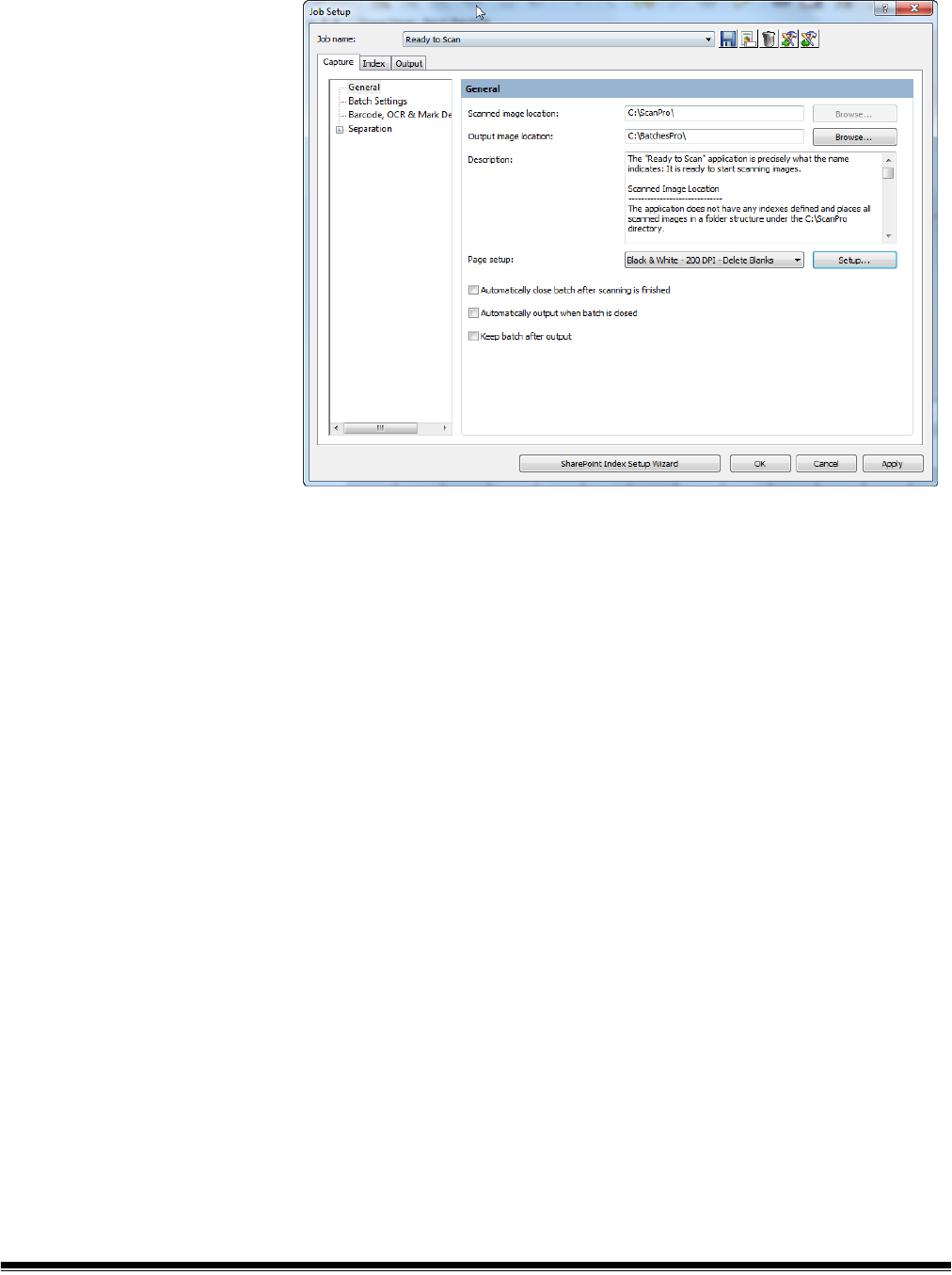
General settings —
Capture tab
Select General on the Capture tab to make or change the following settings:
Scanned image location — displays the current location where scanned
images will be stored for the selected job. If you do not want images scanned
in the displayed location, click Browse to select another location.
Output image location — allows you to select the final destination for your
output images. If you do not want the images to go to the displayed location,
click Browse to select another location.
Description — allows you to enter any important notes as a reminder of the
settings for this job setup.
Page setup — sets the selected default page setup when a new batch is
opened. The list of page setups available to the user during scanning may also
be selected. Select Setup to display the Select Page Setup dialog box. Use
the Add Item and Remove Item buttons to build a list of Selected Page
Setups from the Available Page Setups list. When finished, click OK.
From the Page setup drop-down list, select the default page setup that will be
used when a new batch is opened.
• Automatically close batch after scanning is finished — if checked,
closes the batch in Batch Explorer and the Image Viewer when the scanner
transport stops.
• Automatically output when batch is closed — if checked, processes the
batch to output immediately after the batch is closed.
• Keep batch after output — if checked, saves the batch in the scanned
image location and also creates the output batch.

A-61750 November 2016 13
Batch settings —
Capture tab
Select Batch Settings on the Capture tab to define the batch naming format
for this job and set limits on the number of batch documents or document
pages. For example, if you know that all of your batches contain 100
documents, setting limits will alert you if your batch does not match the number
of documents you are expecting in a batch.
• Batch naming — make the following selections:
- Batch name — select a batch name from the drop-down list. The
Standard batch name is “BatchXXX”. If you want to change your batch
name to “Invoices” and the date, you would click Setup to open the
Standard Setup dialog box. From this dialog box, you can make these
settings. See the next section “Changing the Batch naming settings” for
procedures.
- Next batch number — enter the desired next batch number.
The actual batch number is determined at the time the batch is created.
You will not be able to enter a value if Enable Job Level batch
numbering is unchecked. See “Setting up your Workstation” in Chapter
2 of the User’s Guide for Kodak Capture Pro Software.
• Limits - Documents per Batch — make the following selections:
- Numbers: enter or select the minimum and maximum number of
documents that you want to allow in a batch.
- Warn: enter a document number to serve as a warning that the batch is
approaching its maximum number of documents. When scanning
exceeds this limit (by one or two documents), scanning will stop.
• Limits - Pages per Document — make the following settings:
- Numbers: enter or select the minimum and maximum number of pages
that you want to allow in a document.
- Warn: enter a page number to serve as a warning that the document is
approaching its maximum number of pages. When scanning exceeds this
limit (by one or two pages), scanning will stop.
• Reset document ID: check this box to reset the document counter to 0.

14 A-61750 November 2016
Changing the Batch naming
settings
When you select Standard and Setup from the Batch naming field, the
Standard Setup dialog box will be displayed where you can add or delete
values to the batch name.
The Predefined values list provides values that you can select to add to the
text formula currently in use. You can add any number of items to the batch
name by selecting the item you want from the Predefined values list.
For example, if you want your batch to be labeled with the User name, date
and time, enter the following:
User name, Date (dd), Date (yy), Time24 (HHmmss)
The result would be: John Smith0409115503.
To add a value:
1. Select the value you want to add from the Predefined values list.
2. Click Add Item. The item will be added to the formula.
NOTE: When specifying a path name, the limit is 248 characters.
3. If you want to add more values, repeat Steps 1 and 2.
NOTE: The Add leading zeros and Number length fields become available
when you select the Batch counter value.
4. If applicable, click Add leading zeros to add zeroes the left side of your
sequence number.
5. If applicable, enter a value in the Number length field to limit the number of
predefined values allowed in the text formula.
6. Click OK when finished.
NOTES:
• Clicking Delete Item will remove the last predefined value from the text
formula.
• Clicking Delete Formula will remove the text formula.

A-61750 November 2016 15
When you select Daily Counter Reset and Setup from the Batch naming field,
the Daily Counter Reset Setup dialog box will be displayed where you can add
or delete values to the batch name and select the reset value.
The Predefined values list provides values that you can select to add to the
text formula currently in use. You can add any number of items to the batch
name by selecting the item you want from the Predefined values list. To enable
Daily Counter Reset you must select the predefined value Batch Counter.
When Batch Counter is selected, the counter will increment for each new
batch. When Reset batch number every day is selected, the Batch Counter
will reset to the value specified by Reset value at the start of each day.
NOTES:
• To avoid duplicate batch names, the Text Formula should include at least
one value that changes daily. For example, if you want your batch to be
labeled with the date and an incrementing number, enter the following:
Date(yyyy), Date(MM), Date(dd), Batch counter
For the first batch of the day the result would be: 20120528001
The second batch will be: 20120528002
The first batch of the following day will be: 20120529001
• When using a Kodak Scanner with an imprinter, the Daily Counter Reset will
also reset the scanner counter to a value of 1 at the start of each day.

16 A-61750 November 2016
To add a value:
1. Select the value you want to add from the Predefined values list.
2. Click Add Item. The item will be added to the formula.
NOTE: When specifying a path name, the limit is 248 characters.
3. If you want to add more values, repeat Steps 1 and 2.
NOTE: The Add leading zeros and Reset batch number every day
become available when you select the Batch counter value.
4. If applicable, click Add leading zeros to add zeros to the left side of your
sequence number.
5. If applicable, enter a value in the Number length field to limit the number of
predefined values allowed in the text formula.
6. If applicable, click Reset batch number every day to have the sequence
number reset to a specific value at the start of each day.
7. If applicable, enter a value in the Reset value field to specify the starting
sequence number to be used at the start of each day.
NOTES:
• Clicking Delete Item will remove the last predefined value from the text
formula.
• Clicking Delete Formula will remove the text formula.
Bar Code, OCR & Mark
Detection settings —
Capture tab
See Chapter 4, Bar Code, OCR and Mark Detection Setup for information on
configuring your bar code, OCR and mark detection settings.

A-61750 November 2016 17
Separation settings —
Capture tab
The Separation option on the Capture tab allows you to identify how you want
to separate batches and documents for a job. There are several ways to add
separators to your batches. The following list provides the options you can use
to create separation settings in Kodak Capture Pro Software:
• with a bar code zone (see Chapter 4, Bar Code, OCR & Mark Detection
Setup)
• with an OCR zone (see Chapter 4, Bar Code, OCR & Mark Detection Setup)
• with Patch codes 2, 3 or T (see Chapter 3, Patch Setup)
• by automatically counting pages in a document(s) in a batch (set this option
up using the By Count option)
• with a blank page (set this option up using the By Blank Page option)
• by selecting Document>New or Batch>Next
• by pressing Enter during scanning
• by right-clicking on a page file in the Batch Explorer and clicking Split
The sections that follow provide information and procedures for using Kodak
Capture Pro Software to automatically separate documents or batches by
counting pages and how to use blank page separation.
By Count The By Count separation setting on the Capture tab allows you to enter the
number of documents that each batch will contain, and the number of pages
each document will contain.
1. Choose Batch Level and/or Document Level.
2. Click Every at the Batch Level and enter the number of documents that
the batch must contain before a new batch is created.
3. Click Every at the Document Level and enter the number of pages that a
document must contain before a new document is created.

18 A-61750 November 2016
By Blank page When scanning images, you can insert blank pages to serve as separators.
Kodak Capture Pro Software can recognize blank pages and use them to start
new batches, start new documents, or create attachments to documents.
To use this method enable the By Blank Page option and select the desired
settings.
When you are simultaneously scanning black and white and color/grayscale
images, Capture Pro Software can use either black and white or the color
image to determine a blank page. When the software detects a blank page, all
four images (Color front; Color back; Black and White front; and Black and
White back) of the page are either deleted or attached to the new/current
document, depending on the settings you created.
The size (in bytes) of both the front and back images of a page must fall below
the entered byte value for Capture Pro Software to recognize the page as
blank. If the software does not recognize a blank page, it will ignore it as a
separator.
NOTE: It is recommended that you test these values to ensure that the
software will detect your blank pages as a separator. See the next
section “Testing your settings” for procedures.
Blank Page Image Separator when — activates blank page separation.
• Image size (byte) is below — creates blank page separations based on the
size (in bytes) of the blank page image. Specify the maximum amount of
data (bytes) an image can contain and still be considered blank for each
image type (Black & White, Color/Grayscale) that you will be scanning.
The image size is checked against the raw image coming from the
scanner before operations are performed.
- Black & White: enter the maximum image size in bytes for black and
white. By default, 3000 bytes is suggested for black and white images.
- Color/Grayscale: enter the maximum image size in bytes for color or
grayscale. The maximum image size that can be specified is 1,000,000
bytes (1 MB) to allow for blank page separation when color scanning.
100,000 bytes is recommended.

A-61750 November 2016 19
• Image content (%) is below — creates blank page separations based on
the percentage of image content in the blank page image.
NOTE: If the pages you are scanning are different sizes, a small page may
fall below your blank image byte count even though it contains data.
In this case, you may want to describe a blank image by
specifying% content rather than byte size.
- Black & White: enter the percentage limit for black and white images.
- Color/Grayscale: enter the percentage limit for color and grayscale
images.
Test — opens the Test Image dialog box, which allows you to scan and test
the blank page that is being used as a separator that will be considered blank
when compared against the Image content (%) settings. Use this option to
verify that the software considers the page to be blank. See the next section
“Testing your settings” for more information.
What to do if a page is blank — select one of the options as the next step
after the software recognizes a blank page separation.
• Create a new batch — creates a new batch when a blank page is detected.
• Create a new document — creates a new document when a blank page is
detected.
• Next page stays in current document — deletes the blank page.
• Delete page — when checked, the blank page will not be included in the
batch or document that you are separating on.

20 A-61750 November 2016
Testing your settings 1. Place a document in the scanner that is representative of the document
you want to test for blank page separation.
2. Click Test to display the Test Image dialog box.
3. Click the green Scan button. The results will be displayed in the Test result
box.
• The image is: indicates if the image is Blank or Not Blank.
• Image size is - (bytes): the size of the test image in bytes.
• Content is - %: the percentage of content in the test image.
4. Evaluate the values displayed in the Image size is - (bytes) and/or
Content is - % test result area and click Close.
5. Based on the results, readjust your entered values as needed and click
OK.

A-61750 November 2016 21
Job Setup:
Index tab
Indexing allows you to add data processing functions to your scanning,
capturing and outputting of images at the document and batch level.
You can setup indexing formulas that check the accuracy of metadata
contained in OCR, bar code and mark detection zones. If OCR, barcode or
mark detection reading misinterprets data, the indexing formula can catch the
errors and stop the scan.
You can also setup indexing formulas that output your images to different
locations based on metadata.
• For information on creating input formats, see “Input formats” later in this
section.
• For information on creating output formats, see “Output formats” later in this
section.
• For information on setting up indexes for output to SharePoint, see “Using
the SharePoint Index Setup Wizard” later in this section.
The Index tab on the Job Setup dialog box allows you to define an index field
at the Batch level and Document level. Index fields are setup the same way
for Batch level and Document level.
Following are descriptions of the fields on the Index tab:
Action when audit fails — select the action you want the scanner to take
when an audit fails.
• Continue scanning: keep scanning even when the audit finds illegal index
values.
• Stop scanning: stop scanning and automatically enter Index Editing mode
when the audit finds illegal index values.
Bypass audit during navigation — when checked, disables the audit
function when navigating through documents in the Batch Explorer. The term
"audit" refers to the verification system that verifies all index values comply
with the input/output format.

22 A-61750 November 2016
The Indexes field displays the values that are setup for each index: Name,
Type, Default Value, Input Format, Output Format, Read-only, and Hidden.
You can edit, delete and move a value up or down in the list or add a new
value by using the following buttons:
• Add: opens the Document Add Index Field dialog box to create a new index
field in a document or the Batch Add Index Field dialog box to create a new
field in a batch.
• Edit: opens the Document Edit Index Field dialog box to modify an index
field in a document or the Batch Edit Index Field dialog box to modify an
index field in a batch.
• Delete: removes the selected index field.
• Move up: moves the selected index field up one position in the index list.
• Move down: moves the selected index field down one position in the index
list.
Adding a document
index field
To add a document index field:
1. Select File>Job Setup. The Job Setup dialog box will be displayed.
2. Select a job from the Job Name drop-down list and open the Index tab.
3. Open the Document tab.
4. Click Add. The Document - Add Index Field dialog box will be displayed.
5. Enter the name of your index in the Label field.
6. Enter any notes or comments in the Description field.

A-61750 November 2016 23
7. Select either Single Value, Drop-down list, Drop-down list, multiple
selection or an index API (if available) from the Type field. Single Value
allows to you enter any value. Drop-down list allows you to set up a fixed
list of values to choose from (e.g., if you want to provide a list of countries
to choose from). Drop-down list, multiple selection is similar to Drop-
down list, except you will be able to select multiple values from the list.
NOTE: If you created your own index API it will appear in the Type drop-
down list. When you select an index API, the Setup button will
become available. Click the Setup button to make any
configuration changes.
8. If you selected Single Value, you can check Read only to make this index
non-writable. This protects crucial information from being deleted by users.
9. Check Required to make this index a must-have check item.
10. Check Double Entry to allow an additional data entry of the index field. For
more information, see the section entitled, “Double Data Entry” later in this
chapter. A default value may not be entered when using Double Data
Entry; the Field Type must be Single Value and the field may not be Read
only or Hidden.
11. If you selected Single Value, you can check Hidden to hide this index
from users. This protects sensitive information.
12. Enter a number to define the shortest valid length of the index field in the
Minimum index field length field.
13. Check the Check field during scanning box if you want the system to
check index fields when scanning pages.
14. Enter a predefined value in the Default value field or click Setup to display
the Default Value Setup dialog box and set your own values.
NOTE: If you created a bar code, OCR or mark detection zone, it will be
displayed in the Predefined values list (e.g., BC_[zonename] or
OCR_[zonename]. To use a bar code/OCR zone for an Index field,
you must assign the appropriate BC_[zonename]/
OCR_[zonename] as a default value for the index field. You may
need to scroll to the bottom of the Predefined value list to see the
Bar code/OCR/Mark detection index fields.

24 A-61750 November 2016
Use the Default Value Setup dialog box to create or revise a formula for the
default value of the index field.
• Select a predefined value from the Predefined Values list. The Default
Value Formula (if any) will be displayed on the right side of the box.
• Click Add Item.
NOTE: Delete Item removes the last predefined value that was added
to the Default Value Formula; Delete Formula removes the
entire Default Value Formula.
• Click OK when finished. The revised formula will be populated into the
Default Value text box.
15. Enter your input format. See the section entitled, “Input formats” later in
this chapter for more information.
16. Enter your output format. See the section entitled, “Output formats” later in
this chapter for more information.
17. If you want to define Substitute Characters, click Setup to define
character pairs for automatic substitution. The Substitute Characters Setup
dialog box will be displayed.
• Original column — lists the old characters to be replaced. Select an
original character from the drop-down list at the bottom of the column.
Select the character that you want to replace with a substitute character.
You can select <Space>, <Linefeed> or <Tab>. An original character
can appear only once in the Original column.
• Substitute column — lists the new characters to be put in. Select a
substitute character from the drop-down list at the bottom of the column.
Select <Space>, <Linefeed>, <Tab> or <Replace>. A substitute
character may appear more than once in the Substitute column.
• Add — click to add the original and substitute character pair that you
selected from the two drop-down lists. If you only selected an original
character, Kodak Capture Pro Software will default to <Replace> as the
substitute character.
• Delete — deletes the highlighted original and substitute character pair
from the Original and Substitute columns.

A-61750 November 2016 25
18. If you want to define a value list for the index field, click Setup next to the
List box. The List Setup dialog box will be displayed.
You can select to manually enter list values or import a list of existing
values from an ODBC-compliant data source or a SharePoint library.
Manual entry
• Enter the desired value in the text box in the Value column.
• Enter a description of the value in the text box in the Description
column.
• Click Add to add the value and description pair that you entered in the
two text fields. If you did not create a description, that row in the
Description column will be blank.
Importing a list
• Click Import List.
• Create a new SharePoint or ODBC connection or select and existing
connection.
• Click Next.
• Select the column that will be used to populate the Value field and
select a column that will be used to populate the Description field.

26 A-61750 November 2016
• Click Import. All unique values and the associated descriptions, if
specified, will be imported. If a matching value is already in the list, it will
not be replaced by the imported value. Imported values will be
appended to the list.
NOTE: Click Delete if you want to remove a value or click Delete All to
delete all entries in the list.
•Check Allow any value if you want to set no limitation on index values.
• Select an Indexing action from the drop-down list: Use value only, Use
description only or Use value and description.
• Click OK when finished and return to the Document - Add Index Field
dialog box.
19. Click OK on the Document - Add Index Field dialog box. The new
document index information will be displayed in the table in the Document
tab.
NOTE: To sort the table in ascending or descending order, click on the
appropriate column header. If you click on the Value column
header, the table will be sorted by the values in the Value column.
If you click on the Description column header, the table will be
sorted by the values in the Description column.
20. Click OK to save and exit the Job Setup dialog box.

A-61750 November 2016 27
Editing a document
index field
To edit a document index field:
1. Select File>Job Setup. The Job Setup dialog box will be displayed.
2. Select a job from the Job Name drop-down list and open the Index tab.
3. Open the Document tab.
4. Select an index field.
5. Click Edit. The Document - Edit Index Field dialog box will be displayed.
6. Change the information in the dialog box as desired and click OK.

28 A-61750 November 2016
Adding a batch index
field
To add a batch index field:
1. Select File>Job Setup. The Job Setup dialog box will be displayed.
2. Select a job from the Job Name drop-down list and open the Index tab.
3. Open the Batch tab.
4. Click Add. The Batch - Add Index Field dialog box will be displayed.
5. Complete the information in the dialog box and click OK. See the section
entitled, “Adding a document index field” earlier in this chapter for detailed
field descriptions.
6. Click OK to save and exit the Job Setup dialog box.

A-61750 November 2016 29
PDF Bookmark The PDF Bookmark tab allows you to specify a value for each document
bookmark.
NOTE: For this to work effectively, be sure Group by Multi-Page for each
Batch is selected in the PDF Setup dialog box. See the section
entitled, “Setup options for File (1) and File (2)” later in this chapter.
To define bookmarks:
1. Click Setup to display the Set PDF BookMark Value dialog box.
2. Select the desired predefined value(s) from the list and click Add Item.
3. Click OK when finished.

30 A-61750 November 2016
Double data entry Double Entry allows for two index entry operators to index the documents
separately to improve the accuracy of the index data.
When scanning is complete, the operator selects Index1 from the Index menu
to indicate that the batch is ready for the first index operation.
The first index operator enters the index values for the batch and for each
document. When complete the index operator selects Index2 from the Index
menu to indicate that the batch is ready for the second index operation.
Double entry setup To use Double Entry one or more batch or document index fields must
configured for Double Entry.
1. Select File>Job Setup. The Job Setup dialog box will be displayed.
2. Select a job from the Job Name drop-down list and open the Index tab.
3. Open the Batch or Document tab.
4. Select the desired Double Entry index field and click Edit. The Batch or
Document - Edit Index Field dialog box will be displayed.
5. Check the Double Entry checkbox.
NOTES:
•The Type must be Single Value.
• The index field may not be read-only, therefore, Read-only is disabled.
• The index field may not be hidden, therefore, Hidden is disabled.
• The default value must be left empty, therefore, Default Value Setup is
disabled.
• If any of the above configuration setting are not correct, the Double Entry
checkbox will be unchecked and disabled.

A-61750 November 2016 31
Double entry operation A job that has one or more batch or document index fields configured for
Double Entry is used to scan documents like any other job.
When document scanning is complete and the batch is ready for indexing the
operator selects Index>Index1. This changes the Batch Status from Available
to Index1, meaning the batch is ready for the entry of the first set of index
values.
When the first index operator has entered the index values for all documents
they will select Index>Index2. This changes the Batch Status from Index1 to
Index2, meaning the batch is now ready for the entry of the second set of index
values.
The second index operator will not see the values entered by the first index
operator.
If the value entered by the second index operator matches the first value, no
action is required and indexing continues.
If the first and second values do not match, the Entry Resolution dialog box will
be displayed and the correct entry is selected by the operator.
NOTES:
• If the scanning operator is also entering the first set of index values they will
need to select Index>Index1 followed immediately by selecting
Index>Index2 when scanning and the first index operation is complete.
• The comparison of the Index1 and Index2 values is case sensitive. For
example "UPPER CASE" is not a match to "Upper Case". Also leading
zeros are significant. For example, the value 123 is not a match to 0123.
• Double Entry index fields will have all leading and trailing white space
removed before the value is saved.
For example, if the value “ Shipment “ is entered, the value is saved as
“Shipment”. This means that if Index1 is entered as “ Shipment” and
Index2 is entered as “Shipment “ the values will be a match.

32 A-61750 November 2016
Entry resolution The Entry Resolution dialog box is displayed when the second index value
matches the first index value.
The index operator has the following choices:
• Select the entry made by the first index operator by selecting Entry1.
• Select the entry they made by selecting Entry2.
• Enter a new value in the New Entry field is neither entry is correct.
• Cancel and close the Entry Resolution dialog box if they do not want to
make a choice. If the decision is made to not resolve the mismatched index
value on one or more required index fields, the following message will be
displayed if an attempt is made to output the batch, One or more index
fields require Double Entry. You may not output the batch at this time.
Do you wish to enter Index Mode?
If none of the Double Entry fields are required, the Entry Resolution dialog
box will be displayed on output. All Double Entry index fields with entry
mismatches must be resolved before output.
NOTES:
• If a Double Entry field is not a required field then one or both of the index
entries may be left blank and the Entry Resolution dialog box will not be
displayed; there will be no error on output.
• If both Double Entry values are entered and do not match, the operator must
make a selection on the Entry Resolution dialog box before output.
• An index field enabled for Double Entry may not be used to perform a
Database Lookup or be a field verified or populated by Database Lookup.

A-61750 November 2016 33
Input formats An Input Format is a text expression used to audit the user input for a
particular index field. Its purpose is to prevent incorrect data from being
entered into index fields. The syntax of the input format can be one or a
combination of the following formats:
• Text formats
• Number formats
• Time formats
• Fixed string formats
Input Text formats #
#<maxlength>
#<minlength, maxlength>
# — used to represent a single character of a specific type. # may be one of
the following character types:
9: valid input character set includes '0', '1', ..., '9'
Z: valid input character set includes 'A', 'B', ..., 'Z'
z: valid input character set includes 'a', 'b', ..., 'z'
A: valid input character set includes all characters in Z and z type
C: valid input character set includes all characters in Z and 9 type
c: valid input character set includes all characters in z and 9 type
X: valid input character set includes all characters in Z, z and 9 type
?: valid input character set includes any characters
Examples
999999
Description — 6 numeric characters
Valid input examples
123456
888888
Invalid input examples
ABCDEF wrong character type
1234567 too long
12345 too short
ZZZ999?
Description — 7 characters, first three characters are uppercase alphabetic
letters, next three characters are numeric, last character is any character.
Valid input examples
BAT001%
BOX123a
Invalid input examples
BAT12b3 sixth character must be a numeric
Bat123a second and third letters must be uppercase alphabetic
characters
BAT12345 too long

34 A-61750 November 2016
#<maxlength> — used to represent a variable length text value that has no
minimum length but may have a maximum length.
• If maxlength is 0, there is no limitation on the length of the input value.
• If maxlength is greater than 0, the length of the input value length must be
less than or equal to maxlength.
The maxlength may not be less than 0.
Examples
A<6>
Description — a string that may contain 6 or less alphabetic characters.
Valid input examples
A
ABCDEF
Invalid input examples
ABC123 last three characters must be alphabetic characters
ABCDEFG too long
?<0>
Description – any text value.
#<minlength, maxlength> — used to represent a fixed or variable length
input value that may have a minimum and maximum length.
•If minlength is 0, the input string may be empty.
•If minlength is greater than 0, the input value length must greater than or
equal to minlength.
•The minlength may not be less than 0.
•If minlength is equal to maxlength, the input value must have the specified
number of characters.
Examples
X<2,10>
Description — an input value that contains 2 to 10, upper or lower case
alphabetic or numeric characters.
Valid input examples
Batch0001
1234abcABC
A1
Invalid input examples
Batch-001 The ‘-‘ character is not a valid ‘X’ character
A too short
1234abcdABCD too long
AB Inc space character is not a valid ‘X’ character

A-61750 November 2016 35
?<3,0>
Description — a string that contains 3 or more characters of any type.
Valid input examples
ABC
+%=
ABC Company
Invalid input examples
A1 too short
A<4,4>
Description — a string of exactly 4 alphabetic characters. The same format as
AAAA.
9<0,3>
Description — a string of 3 or less numeric characters. String may be empty.
A<3,2>
Description — invalid input format, maxlength must be greater or equal to
minlength if maxlength is greater than 0.
Input Number formats #
#(min, max)
#(min, max]
#[min, max}
#[min, max]
# — used to represent one of the following number types:
i : integer number that may be positive or negative and does not contain a
decimal point
n : any number, positive or negative and may contain a decimal point.
The value range or precision of the number is limited by the operating system.
The valid number range is typically:
i : -2,147,483,648 to 2,147,483,647
n : 1.7 E ±308 ( 15 digits )
The min and max values define the range of the number value.
The value of min and max must be consistent with the number type. For
example, if the number type is i, both min and max must be a valid integer
number.
The character * may be used in place of min or max and represents an infinite
value or no limit.
The max value must be greater than or equal to the min value.
( : input value must be greater than min.
) : input value must be less than max.
[ : input value must be greater than or equal to min.
] : input value must be less than or equal to max.

36 A-61750 November 2016
Examples
i
Description — any integer number.
Valid input examples
123
-456
Invalid input examples
123.456 must be an integer. Decimal values are not allowed
-123. integer values cannot have a decimal point
n
Description – any integer or decimal number.
Valid input examples
123
123.456
-123.
#(min, max) — used to specify a value that is greater than min and less than
max.
Examples
i(-100, 100)
Description — any integer number greater than –100 and less than 100.
Valid input examples
-99
0
99
Invalid input examples
-100 too small, must be greater than –100
-99.9 must be an integer (decimal not allowed)
100 too large, must be less than 100
#(min, max] — used to specify a value that is greater than min and less than
or equal to max.
Examples
i(-100, 100]
Description — any integer number greater than –100 and less than or equal
to 100
Valid input examples
-99
0
100
Invalid input examples
-100 too small, must be greater than –100
-99.9 must be an integer (decimal not allowed)
101 too large, must be less than or equal to 100

A-61750 November 2016 37
#[min, max) — used to specify a value that is greater than or equal to min
and less than max.
Examples
n[-100, 100)
Description — any number greater than or equal to –100 and less than 100.
Valid input examples
-100
-99.9
99.9999
Invalid input examples
-100.1 too small, must be greater than –100
100 too large, must be less than 100
#[min, max] — used to specify a value that is greater than or equal to min
and less than or equal to max.
Examples
n[-100, 100]
Description — any integer number greater than or equal to –100 and less
than or equal to 100.
Valid input examples
-100
0
100
Invalid input examples
-100.1 too small, must be greater than or equal to –100
100.001 too large, must be less than or equal to 100
i[100, *)
Description — any integer number greater than or equal to 100
Valid input examples
100
1000
Invalid input examples
99 too small, must be greater than or equal to 100
100.5 integer values cannot have a decimal point
i(-1.0, +1.0)
Description — this is an invalid input format because the min and max are not
integer values as the “i” specifies.
n(+1.0, -1.0)
Description — this is an invalid input format because max is less than min.

38 A-61750 November 2016
Input time formats T<timeformat>
timeformat is a text string expression of the date/time value. The syntax can be
one or a combination of the following elements:
The following date/time elements cannot be repeated in the timeformat. For
example, if you have selected yyyy for year date format, you cannot use yy or
another yyyy in the timeformat. This limitation includes:
yyyy and yy
dd and DDD
HH and hh
HH, TT, T, tt and t
Examples
T<yyyyMMdd>
Description — a full date.
Valid input examples
20051025
19000101
Invalid input examples
2005/10/25 unexpected character /
20051032 invalid date
20050229 invalid date (because the year 2005 was not a leap year)
00990101 date is earlier than 1000
yyyy year (1000-9999)
yy year (00-99, for 00-79, it means 2000-2079, for 80-99, it means
1980-1999)
MM month (01-12)
dd day of month (00-31, validate date when year and month are available)
DDD day of year (001-366, validate date when year and month are available)
HH hour (00-23)
hh hour (01-12)
mm minute (00-59)
ss second (00-59)
TT AM/PM
T A/P
tt am/pm
t a/p
"text" text is a fixed text string.

A-61750 November 2016 39
T<MMdd>
Description — a date without a year specified.
Valid input examples
1201
1231
0229
Invalid input examples
0001 invalid month
0230 invalid date of February regardless if it is a leap year
ABCDEF invalid text
T<HH":"mm":"ss>
Description — a time with : as separator.
Valid input examples
23:59:59
00:00:00
Invalid input examples
99:59:00 invalid hour
120000 no separator
T<hhmmsst>
Description — a full time.
Valid input examples
010000a
120000p
Invalid input examples
010000A A should be lower case
000000a invalid time
1355101 invalid hour must be 00-12
T<HHmmssTT>
Description — this is an invalid input format because HH represents 00 to 23
hours and TT represents AM/PM which is not valid with a 24-hour time string.
T<yyyyMMyyyy>
Description — this is an invalid input format for yyyy because it was used more
than once in a timeformat.

40 A-61750 November 2016
Input fixed string formats “text”
text is any text string. Because the start and end of the text string is defined by
the character “ (double quote), the double quote character is not allowed in the
text string. A text string format is normally used in combination with other input
formats.
Examples
999”-”99”-”999
Description — fixed string (to define a United States Social Security number).
"ID"
Description — fixed string.
Valid input examples
ID
Invalid input examples
XX does not match text in format. Input must be: ID
“Text”ABC””
Description — this is an invalid input format because it includes two extra “
characters in the format.
Combination input
formats
An input format can consist of multiple formats that are used in combination.
To use multiple formats to define an input format connect the format
expressions together with or without a blank space.
No format expression may follow a format that is of variable length. For
example: A<1,0>”-Comment” is not valid because A<1,0> may be any length.
The format: “Comment-“A<1,0> is valid because the variable length format is
at the end of the combination input format.
Following are valid and invalid combination formats.
Examples
"ID"999999
Description — combined formats: "ID" and 999999.
Valid input examples
ID123456
Invalid input examples
IDabcdef the letters abcdef must be numbers
id123456 the first two letters id do not match format which is ID
“DATE”T<yyyyMMdd>
Description — combined formats “DATE” and T<yyyyMMdd>.
T<“DATE”yyyyMMdd> is equivalent to the above format.
Valid input example
DATE20051025

A-61750 November 2016 41
Invalid input examples
n?<0>
Description — this is an invalid input format for the number specified. n is a
variable length and no additional format can follow it.
A<2,3>”XX”
Description — this is an invalid input format because A<2,3> specified a
variable length and no additional format can follow it.
A<3,3>”XX”
Description — combined with formats: A<3,3> and “XX”.
Valid input example
XYZXX
Invalid input examples
XXXXXX unexpected X at the end of the text string.
20051025 the text DATE must proceed the date
DATE20051032 October does not have 32 days
XXXXXXX too long, extra X at the end of the string

42 A-61750 November 2016
Index Default value
specification
Default value expression is a text expression to set the default value for a
particular index field. In default value expression, you need to define the
default value by using one or more predefined tags (i.e., system, barcode/
OCR/mark detection value) or a fixed string. You can also define multiple
options of the default value by connecting tags with the OR keyword.
Tags
<tagname>
<tagname:transformexpression>
tagname is a predefined system, OCR, mark detection or barcode zone data
expression. System data expressions include date, time, Station ID and name,
Job and User name, batch and workgroup path, document and page ID and
Last Value.
transformexpression is used to transform the format of the system or
barcode/OCR value. For example the date is expressed as MMddyy, the
transform expression may change the format to MM/dd/yyyy. See the next
section for a description of transform expression.
Check Double Entry to allow an additional data entry of the index field. For
more information, see the section entitled, "Double Data Entry" elsewhere in
this chapter. A default value may not be entered when using Double Data
Entry; the Field Type must be Single Value and the field may not be Read only
or Hidden.
NOTES:
• The Type must be Single Value.
• The index field may not be read-only, therefore, Read-only is disabled.
• The index field may not be hidden, therefore, Hidden is disabled.
• The default value must be left empty, therefore, Default Value Setup is
disabled.
• If any of the above configuration settings are not correct, the Double Entry
checkbox will be unchecked and disabled.
Fixed string formats "text"
text is a fixed text string. The string delimiter character " (double quote) is not
allowed in the format. A fixed text string format is normally used in combination
with other formats.
Using multiple tags A default value may include more than one tag expression used in
combination. For example you may want the default value to include the date,
time and Station ID separated by a dash. To do this concatenate them
together.
For example:
<sys.date:ddMMyy>"-"<sys.time:hhmmss> "-“ <sys.stationid>

A-61750 November 2016 43
Using the OR keyword The OR keyword may also be included in the default value expression. This
may be useful when a value may not always be present. You may want to set
the default value to the value of a barcode that appears on the document.
For example:
<barcode.UPI ID Number>
If no barcode is found on the document, the index field will be empty. The OR
keyword can be used to provide an alternate value.
For example:
<barcode.UPI ID Number> OR “Barcode not found on document:”
<app.documentid>
As many expressions as needed may be OR’d
Default Value Option #1 OR Default Value Option #2 OR ... OR Default Value
Option #n
The system will check the Default Value Option # one-by-one from left to right,
and use the first valid data to initialize the index data.
Available Tags — the following displays the available default value tags:
NOTE: Barcode/OCR/Mark Detection zones will be displayed at the bottom of
the default value list.

44 A-61750 November 2016
Default value using
LASTVALUE
When lastvalue is selected as the default value, Capture Pro Software
automatically uses the last assigned value for an index field from the previous
document (for document indexes) or previous batch (for batch indexes)
whenever a new document or batch is created. This is useful, for example, in a
backlog application, when you scan folders of documents with the same date.
When you start scanning into a new batch, and no index value is assigned yet,
enter the date once and it remains the same for every new document after that
until you change it.
lastvalue is also useful when performing bar code indexing but not every
document scanned will have a bar code attached to it. For example, a default
value expression of:
<barcode.Patient ID> OR <app.lastvalue>
means that when a new document is scanned, assign the index field value to
the value of the bar code zone "Patient ID" <barcode.Patient ID>. However, if
the document did not have a bar code on it, assign the index field instead to
the value of the previous document OR <app.lastvalue>.

A-61750 November 2016 45
Transform Expressions A Transform Expression is a text expression to format or transform the data of
a particular field into a default or output value. Transform Expressions are used
to define default values and output format for an index field.
Default value specification: when a new batch or document is created, the
index field will be populated with a value based on the default value
specification. The default value specification is entered on the Index tab and
takes the form <tagname> or <tagname:transform expression>. The transform
expression is described below.
Examples:
<sys.date:ddMMyy>
<sys.stationid:[1,5]>
Output format: when a batch is output, the index data for the batch and for
each document in the batch will be reformatted based on the output format.
For instance, a date index with a value of MMddyy can be reformatted to:
MM/dd/yyyy.
The output format is entered on the Index tab and takes the form:
transform expression.
Examples:
ddMMyy
[1, 5]
The syntax can be one or a combination of the following formats:
• Text formats
• Number formats
• Time formats
• Fixed string formats
Transform text formats [start]
[start, end]
[index, ‘delimiter’]
[start; len]
These formats are used to extract a sub-string from the original index value.
[start] — used to extract a sub-string starting at the position start to the end of
the original value.
• If start is a positive number, the start position will be counted from the
beginning of the original value.
• If start is a negative number, the start position will be counted from the end
of the original value.
• If start is 0 or *, the start position will be the beginning of the original value.

46 A-61750 November 2016
Examples
[5]
Description — get sub-string from the 5
th
character to the end of the original
value.
“ABCDEFGHIJKL” “EFGHIJKL”
“1234567890” “567890”
“1234” “”
[*]
Description — get full string.
“ABCEDFG” “ABCDEFG”
“1234567” “1234567”
[start, end] — used to extract a sub-string starting at the position start and
ending at the position end of the original value.
• If end is a positive number, the end position will be counted from the
beginning of the original value.
• If end is a negative number, the end position will be counted from the end of
the original value.
• If end is 0 or *, the end position will be the end the original value.
• If the start position is after the end position, the sub-string will have the
reverse order of the original value.
Examples
[1, 2]
Description — get sub-string from the 1
st
character to the 2
nd
character of the
original value.
“ABCDEFG” “AB”
“123456” “12”
[-4, -1]
Description — get sub-string from the 4
th
from the last character to the last
character of the original value.
“ABCDEFGHIJK” “HIJK”
“1234567890” “7890”
[*, 5]
Description — get sub-string from the 1
st
character to the 5
th
character of the
original value.
“ABCDEFGHIJK” “ABCDE”
[5,2]
Description — get sub-string from the 5
th
to the 2
nd
character in reverse order
of the original value.
“ABCDEFGHIJK” “EDCB”
“1234567890” “5432”

A-61750 November 2016 47
[2, -2]
Description — get sub-string from the 2
nd
character to the 2
nd
from the last
character of the original value.
“ABCDEFGHIJ” “BCDEFGHI”
“1234567890” “23456789”
“AB” “BA”
“A” “A”
[index, ‘delimiter’] — used to extract the element at the position specified by
index where each element in the index data is separated by the character
delimiter. The first element is index 1.
NOTE: This transform expression is especially useful when assigning data
elements in a PDF417 bar code to different index fields. It is also
useful when assigning different lines of multi-line OCR results to
different index fields. The delimited produced by multi-line OCR is the
carat (^) character.
Examples
[2, ‘^’]
Description — get the 2
nd
element in the multi-line OCR where elements are
separated by the ‘^’ character.
“John Smith^123 Main Street^Some City” “123 Main Street”
[3, ‘*’]
Description — get the 3
rd
element from the PDF417 barcode where elements
are separated by the ‘*’ character.
“John Smith*123 Main Street*Some City” “Some City”
[start; len] — used to extract a sub-string for the position start for len
characters.
Examples
[2;3]
Description — get sub-string from 2
nd
character with a length of 3 characters.
“ABCDEFGHIJ” “BCD”
“1234567890” “234”
“AB” “B”
“A” “”

48 A-61750 November 2016
Transform number
formats
#<width, fracwidth>
#<width, fracwidth, padding>
#<textformats, width, fracwidth>
#<textformats, width, fracwidth, padding>
0width
# can be one of the following characters to define the desired number type.
n: generic number
N: generic number with sign
p: percentage number
P: percentage number with sign
c: currency number
C: currency number with sign
The value range or precision of the number is limited by the operating system.
The valid number range is 1.7E ±308 (15 digits).
#<width, fracwidth> — used to format a number that has at most, width
number of characters and at most, fracwidth characters after the decimal.
width defines the total number of digits to be included in the output string.
• If width is a positive number, the output text will be right-aligned with the
padding character (if any) on the left.
• If width is a negative number, the output text will be left-aligned with the
padding character (if any) on the right.
fracwidth defines the number of digits to be displayed to the right of the
decimal point.
The number 0 is used to show no decimal point.
The * character is used to show a default of 6 digits to the right of the decimal
point.
Examples
n<20,2>
Description — a generic number with a maximum width of 20 characters and 2
digits after the decimal point. The string will be right-aligned.

A-61750 November 2016 49
Examples
“324.5” “ 324.50”
“abcd” “ 0.00”
p<-20, 2>
Description — a number expressed as a percentage with a total width of 20
characters and 2 digits after the decimal point. The string will be left-aligned.
Examples
“0.12abc” “12.00% “
“-43” ”-4300.00% “
c<20, 0>
Description — a number expressed as currency with a total width of 20
characters and no decimal point. The string will be right-aligned.
Examples
“12345.6” “ 12,346”
“-12345.6” “ –12,346”
C<20, 2>
Description — a number expressed as signed currency with a total of 20
characters and 2 digits after the decimal point. The string will be right-aligned.
Examples
“12345.6” “ +12,345.60”
“-12345.6” “ –12,345.60”
“abc” “ +0.00”
“-0.001” “ –0.00”
“-0.00” “ +0.00”
#<width, fracwidth, padding> — used to format a number that will be padded
with the padding character, to the specified width, including fracwidth
characters after the decimal point.
padding defines the character to fill the space if the formatted text is less than
the width defined.
Example
P<20, 3, ‘#’>
Description — a number expressed as a signed percentage with a total width
of 20 characters, 3 digits after the decimal point and padded with the ‘#’
character.
Examples
“0.12abc” “############+12.0000%”
“-43” “##########-4300.000%”
#<textformats, width, fracwidth> — used to format a number that is
extracted from a string using textformats.
textformats specifies how to extract the number from the original index string.
See the Output formats section.
Example
N<[2], 20, 3>
Description — a signed number with a total width of 20 characters and 3 digits
after the decimal point. The number will be extracted starting at the 2
nd
character in the original string.

50 A-61750 November 2016
Examples
“A12345.6” ” +12345.600”
“-12345.6” “ +12345.600”
“TT9000” “ +0.000”
“—9999” “ –9999.000”
N<[2, ‘^’], 20, 3>
Description — a signed number with a total of 20 characters and 3 digits after
the decimal point. The number will be extracted from the 2 elements in the
string, where the elements are separated by the ‘^’ character.
Example
“12345.6^45678.9” “ +45678.900”
#<textformats, width, fracwidth, padding> — used to format a number that
is extracted from a string using textformats and padded with the specified
character.
This format is an extension of the format #<textformats, width, fracwidth>
where the output string will be padded with the specified character.
0width — used to zero-fill a number to the minimum specified width.
Examples
010
Description — a zero-filled number with a total width of 10 characters.
Examples
“123” “0000000123”
“0” “0000000000”
03
Description — a zero-filled number with a total width of 3 characters.
Example
“1” “001”
“1234” “1234”

A-61750 November 2016 51
Transform time formats #
# — may be one or any combination of the following formats:
When using time formats, you must specify an Input Time format to define the
contents of the string that is to be formatted for output.
Examples
ddMMyyyy
Description — a date in day, month and year format.
Examples
Input Format: T<yyyyMMdd> the string “20051026” “26102005”
Input Format: T<yyyyMM> the string “102005” “102005”
yyyy year (1900-2099)
yy year (00-99)
y year
MM month (01-12)
M month (1-12)
dd day of month (01-31)
d day of month (1-31)
D day of week (1: Sunday, 2: Monday, etc.)
DDD day of year (001-365)
HH hour (00-23)
H hour (0-23)
hh hour (01-12)
h hour (1-12)
mm minute (00-59)
m minute (0-59)
ss second (00-59)
s second (0-59)
TT AM/PM
T A/P
tt am/pm
t a/p
ww week of year (01-53)
w week of year (1-53)

52 A-61750 November 2016
Fixed string formats text”
text is any text string. Because the start and end of the text string is defined by
the character “ (double quote), the double quote character is not allowed in the
text string. A text string format is normally used in combination with other input
formats.
Examples
"ID-"[*]"-XX"
Description — output fixed text string of "ID".
Examples
"20051026" ==> "ID-20051026-XX"
Combining Transform
formats
A Transform Expression can consist of multiple formats that are used in
combination. To use multiple formats to define a Transform Expression simply
connect the format expressions together with or without a blank space.
Examples
"Revenue"c<20, 2>
Description — combination with formats "Revenue" and c<20, 2>.
Examples
"123456" ==> "Revenue 123,456.00"
yyyy"/"MM"/"dd"-"HH":"mm":"ss
Description — combined with formats: yyyy, "/", MM, "/", dd, "-", HH, ":", mm, ":"
and ss.
Examples
"20051026080405PM" ==> "2005/10/26-20:04:05"
Input Format: T<yyyyMMddhhmmssTT>
Output formats An Output Format is a text expression to format the data of a particular index
field into an output value. Transform Expressions are used to define the output
format for an index field.
Output format: when a batch is output, the index data for the batch and for
each document in the batch will be reformatted based on the output format.
For instance, a date index with a value of MMddyy can be reformatted to:
MM/dd/yyyy.
The syntax can be one or a combination of the following formats:
• Text formats — see Transform Expressions, Text formats
• Number formats — see Transform Expressions, Number formats
• Time formats — see Transform Expressions, Time formats
• Fixed string formats — see Transform Expressions, Fixed string formats
• Combination formats — see Transform Expressions, Combining
Transform formats

A-61750 November 2016 53
Index tab — Database
Lookup
Database Lookup can be used to populate or validate batch and document
index fields from ODBC (Open Database Connectivity) compliant data
sources. A configuration wizard is used to specify the data source, define how
the lookup is performed and what data is used to populate index files or
validate the contents of index fields. A job setup may contain more than one
Lookup. Each Lookup can be to a different data source and used to populate
or validate selected index fields. Lookups may occur during scanning when the
index value used for the Lookup is a result of a barcode reader or an OCR
action. Each Lookup takes the form: SELECT <table column 1>, <table column
2>, ... <table column n> FROM <data source> WHERE <table column x> =
<index field value> or select: WHERE <table column x> = <index field value>
AND <table column y> = <index field value>.
Configuring Database
Lookup
Configuring Database Lookup starts with defining the batch and document
index fields that will be used by the Lookup. Database Lookups are configured
for each job.
NOTE: Defining index fields in Job Setup has not changed from previous
versions of Kodak Capture Pro Software.
To add or edit a new lookup:
1. Click File>Job Setup. The Job Setup dialog box will be displayed.
2. Select a job setup from the Job Name drop-down list. The settings for the
job setup will be displayed.
3. Select the Index tab.
4. Select the Database Lookup tab. The Lookups table will be displayed with
the following fields: Name, Input Index Field, Output Index Field (Batch)
and Output Index Field (Document) for each Lookup.

54 A-61750 November 2016
5. Click Add. The Database Lookup Wizard will be displayed.
6. Enter the name of your Lookup in the Lookup name field.
7. Click Browse to open the Select Data Source dialog box.
• Select an existing File Data Source or Machine Data Source, or click
New to create a new data source. Depending on the type of data source
you have selected, you will be prompted for additional information.
• Click OK after all required information has been entered.
8. Select the table or file from the Database table drop-down list that contains
the data that will be used to populate or validate the index fields.

A-61750 November 2016 55
9. Click Next to define how you want to do the data lookup.
•Select Validate index fields from Lookup results if you want to verify
one or more index field values that match data in your data source.
•Select Populate index fields from Lookup results if you want to fill in
one or more index fields from the Lookup.
10. Select the index field(s) to be used by the Lookup to find matching values
in the selected database from the Lookup index field drop-down list. This
list contains all defined document and batch index fields. If a single index
field is to be used for the Lookup, it must be in the left column before the
“And”. If two Lookup index fields are provided, then only database records
that contain both values will be matched. At the time of index data entry, if
one value is not known, it may be replaced by the asterisk (*) character.
For more information, see the section entitled, “Using Database Lookup”
later in this chapter.
11. Select the table column(s) to be searched for values matching the selected
Lookup index field from the Lookup table column drop-down list. This list
contains all table column names from the selected database table.
12. For each batch or document index field that you want to populate or
validate, select the database column that contains the desired data. Click
in the column to the right of the index field name and select the database
column from the drop-down list.

56 A-61750 November 2016
13. Click Next to choose the database lookup options.
14. Select the desired Lookup options:
• Disable Lookup: when checked, Lookups will not be performed during
scanning. This may improve performance with large or remote
databases. Lookups will continue to occur in Edit Index mode and when
the batch is output.
• Display multiple lookup results if there is more than one result:
when unchecked, the Multiple Lookup Results table will not be
displayed during scanning. Multiple Lookup results will be resolved in
Edit Index mode, allowing scanning to continue uninterrupted.
• Lookup will overwrite existing index value: when checked, the
Lookup will always populate an index field with the lookup value in the
database, as long as the database entry has a value (i.e., is not empty
or null). If you want users to be able to manually enter data into an index
field that Database Lookup is populating, then this option should be
unchecked.
NOTE: Database Lookup will never overwrite data when the batch is
output.
• Disable Lookup during Output: when checked, no Lookup (populate
or validate) will occur during output. If unchecked, empty fields will be
populated and missing or multiple records will be ignored. Validation will
fail if no matching record is found.
• Maximum multiple results to display: when multiple lookup results
are found, a table of the results will be displayed allowing you to chose
the correct result. The value entered will limit the length of the table.

A-61750 November 2016 57
15. Click Next to test the Lookup.
16. Click Test Query. The Test Query dialog box will be displayed.
17. Enter a valid value for the parameter that is used to perform the Lookup. If
you leave the value blank, the first 25 records in the data table will be
displayed.
18. Click OK.

58 A-61750 November 2016
Using Database Lookup After configuring a job to do a Database Lookup, it is important to understand
when the Lookup will be performed. The following are common scenarios:
During Scanning - Populating
index fields
When Disable Lookup during capture is not checked, Lookups will occur on-
the-fly during scanning.
The Lookup will only take place when the index field that is being used for the
Lookup has a value that was populated during scanning (e.g., as a result of a
barcode, OCR or mark detection zonal read).
During Scanning - Validating
index fields
When Disable Lookup during capture is not checked, Lookups configured for
index field validation only will also occur on-the-fly during scanning.
The Lookup Validation will only take place when the index field that is being
validated has a value that was populated during scanning (e.g., as a result of a
barcode, OCR or mark detection zonal read).
NOTE: When Disable Lookup is not checked, Database Lookups will always
be performed during scanning. Even if the Index Field setup option
Check field during scanning is disabled, the Database Lookup
validation will still be performed.
Edit Index mode After scanning has been performed and the user enters Index mode
(Index>Edit Index Fields), the Lookup will always be performed on a
document whenever the document is navigated to while in indexing mode.
If the index field that is being used for the Lookup already has a value (e.g.,
from barcode, OCR or mark detection zonal read) then the Lookup for a
document will be performed automatically when navigating to the document.
If data is manually being entered in the index field, then the Lookup will be
performed when the user leaves the index field. If the Tab key is used to
navigate away from the index field just entered, the results of populating the
other index fields will be displayed for verification. If the Enter key is used or
one of the other indexing mode function keys (i.e., F9, F10, F11) to navigate to
another document, then the Lookup will be performed and the other index
fields will be populated. However, you will not see the results of the Lookup as
that document is no longer being displayed in indexing mode.
If the Lookup index field is populated using Drag n’ Drop OCR or clicking OCR,
then the Lookup will be performed immediately and the results of populating
the other index fields will be displayed for verification.

A-61750 November 2016 59
If the value being used for Lookup is only partially known, the asterisk
character ' * ' may be used to replace the unknown character(s). The asterisk
character must be the last character. For example, if the Lookup value is a
phone number but only the first four digits are readable, the value "557-3*"
may be entered. All phone numbers beginning with "557-3xx...." will be
retrieved from the database and you may select the correct value.
When a Lookup is based on two values and only one value is known, the
asterisk character may be used in place of the unknown value. For example,
the Lookup is based on Last_Name AND First_Name and the Address will be
looked up. If only the last name is known, it is entered in the index field "Last
Name" and the asterisk character is entered in the index field "First Name". If
only one record is found for the last name entered, the first name and address
will be populated. If multiple records are found for the last name, the Multiple
Results dialog box will be displayed and the correct entry may be chosen.
Batch output Database Lookup only occurs on output if the Disable Lookup on Output
option is not checked. When you click the Output tool, as part of Index field
validation, Database Lookup for populating and validating index fields is
performed immediately before the batch is queued for output processing. If a
Database Lookup is populating index fields, errors will be ignored. If no record
is found or multiple records are found, the current value in the index field will
be unchanged or left empty. If a Database Lookup is validating index fields, an
error will occur if no matching record is found. The batch will not be submitted
for output and the error must be corrected before the batch can be
successfully output.
If a batch is output from the Batch Manager screen or is automatically output
from Job Setup, Database Lookup is performed immediately as part of the
background batch processing. If a Lookup fails, the batch will be put into Index
Error status.
When the batch is opened to correct the error, the document that had the
Lookup failure will be automatically displayed and you can go into Index mode
to correct the indexing problem and re-submit the batch for output processing.

60 A-61750 November 2016
Job Setup:
Output tab
The Output tab is where you set up your output options for your job setup.
• Destination — allows you to make settings for the format of the output,
where to send the output, and how to index it. The Destination options are:
-Credentials: allows you to provide user access credentials for
destination network file shares.
- File (1) and File (2): allows you to select your file format (TIFF, JPEG,
PDF, PNG, etc.) and type of output (e.g., black and white, color/
grayscale).
- System (1) and System (2): allows you to select the System Output
Destination for your job setup.
- E-mail: allows you to setup the software to automatically e-mail the
output.
- Print: allows you to setup the software to automatically print the output.
• Advanced Options — allows you to apply Kodak Capture Pro Software
image processing options to the output.
• Invoke Other Program — allows you to use another software application
on your output.
Credentials Select Credentials when the Destination output location is a network share for
which the Capture Pro operator may not have access.
• Add — displays the Credentials Setup dialog box.
• Enter the server and share name in the format \\server _name\share_name.
The server machine name or the server IP address may be entered.

A-61750 November 2016 61
• Remove — removes the selected credentials.
• Properties — displays the properties of the selected credentials. The user
name and password may be changed.
The Credentials are not shared between job setups. If two jobs setups use the
same network share, the credentials must be added to both job setups. This
allows different job setups to access the same network share using different
credentials.
The credentials will always be used even if the current user has access to the
network share.
The Credentials may be used for File (1), File (2), System (1) and System (2)
output. The use of Credentials is especially useful when using the optional
Capture Pro Network Edition - Remote Output Server. Because the Remote
Output service has no user, the Credentials are used to provide access to
external shares.
Destination options:
File (1) and File (2)
File (1) option — select a file format (TIFF, PDF, JPEG, PNG, etc.) for your
output. Your choice of formats will depend upon your type of output:
• All (black and white and color/grayscale)
• Black and white
• Color/grayscale — when this is selected, a Filter option may be selected to
only output grayscale images or color images.
NOTE: For a description of the file format dialog boxes, see the section
entitled, “Setup options for File (1) and File (2)” later in this chapter.

62 A-61750 November 2016
• Location — shows the output location for File (1). To change settings, click
Setup to open the Location Setup dialog box. For more information about
the Location Setup dialog box, see the section entitled, “Building location
and filename formulas using the Location Setup dialog box” later in this
chapter.
• File Name — shows the file name for File (1).
File (2) option — same as File (1). You can choose different settings for File
(2) or use the same settings as in File (1).
Under the File (1) or File (2) options, you can select the Index option. The
following indexing options will be displayed.
• Batch Index file
• Document Index file
• Image Index file
Setup options for File (1)
and File (2)
When you select a file format (i.e., TIFF, PDF, JPEG, PNG, etc.) for your
output, your choice of formats will depend on how you configure the setup for
that file format.
• Click Options for the file format you want to configure.
When the Options button is selected, a dialog box for the file format you
selected will be displayed.

A-61750 November 2016 63
Selecting ABBYY OCR as
your file format
If you have access to a working ABBYY Recognition Server then this file
format will use your ABBYY Recognition Server to process and OCR
documents in the batch. This is not a new file format. It is an interface to your
ABBYY Recognition Server that allows Capture Pro Software to submit
documents to ABBYY for OCR processing. After OCR processing the
documents are returned to Capture Pro for output.
Every user defined ABBYY workflow will specify an Input folder for documents
to be processed and an Output folder for documents that have been
processed. Capture Pro Software will create the ABBYY XML Tickets that
define what documents are processed by the ABBYY workflow. To keep
batches from multiple workstations running Capture Pro Software separate,
each workstation will create separate sub folders in the appropriate Input
folder.
Before defining an ABBYY file format:
• Make sure the ABBYY Input and Output folders for each defined workflow
are shared and accessible by Capture Pro Software.
• Setup the credentials that will be used by Capture Pro Software to access
the shared Input and Output folders on the ABBYY Recognition Server. For
more information about setting up credentials, see the section entitled,
“Credentials” earlier in this chapter.
1. Select ABBYY OCR from the drop-down list and click Options.

64 A-61750 November 2016
The ABBYY Output Setup dialog box will be displayed.
The Server input folder and the Server output folder fields will display the
path of the ABBYY Recognition Server Input and Output Folders as
defined by the ABBYY workflow.
2. Select either Single Page or Multi-Page as the way to group your image
files in output. Every input (scanned) image file will be a separate output
file.
• If you select Single Page, every image you scan is a separate image
file in output. Therefore, if you scan a page, you will have two separate
image files in output (one for the front and one for the back). If you are
scanning dual stream, you will have four image files in output.
• If you select Multi-Page, the For each drop-down list becomes
available.
- For each: Page - every image for every page scanned becomes
one file. When you open the file, there will be two images, one for
the front and one for the back. If you are scanning dual stream, you
will have four images.
- For each: Document - every page scanned into one document will
become the contents of one file. There may be several (or many)
images in one file.
- For each: Batch — all images scanned into the batch will become
one output file. There may be many images in the output file.

A-61750 November 2016 65
3. OCR will be performed to allow searching for specific text in output files.
Select the OCR language that your scanned documents will contain, for
the most accurate character recognition. If you have a mixed document set
that may contain multiple languages, you can select one or more
secondary languages.
4. The Max time to process Batch is the time in minutes, Capture Pro
Software will wait for ABBYY to process the batch of documents. If ABBYY
has not completed the OCR of the documents within the specified time, the
batch output will fail.
Selecting PDF as your file
format
If you select PDF as your file format, the PDF Setup dialog box will be
displayed.
1. Select either Single Page or Multi-Page as the way to group your image
files in output. Every input (scanned) image file will be a separate output
file.
• If you select Single Page, every image you scan is a separate image
file in output. Therefore, if you scan a page, you will have two separate
image files in output (one for the front and one for the back). If you are
scanning dual stream, you will have four image files in output.
• If you select Multi-Page, the For each drop-down list becomes
available.
- For each: Page — every image for every page scanned becomes
one file. When you open the file, there will be two images, one for the
front and one for the back. If you are scanning dual stream, you will
have four images.
- For each: Document — every page scanned into one document will
become the contents of one file. There may be several (or many)
images in one file.
- For each: Batch — all images scanned into the batch will become
one output file. There may be many images in the output file.

66 A-61750 November 2016
2. Select one or more Additional PDF formats: PDF/A, PDF-MRC, Fast
Web View, PDF BookMark or Long PDF.
•Select Fast Web View if you want to configure the PDF file for faster
viewing if the files are large and downloaded from the web site.
•Select PDF BookMark when you want to bookmark each document in
the PDF file. Group by Multi-Page for each Batch must be selected.
Specify the value of each document bookmark using the PDF
BookMark tab found on the Index tab. System and/or Index values
may be used to produce unique bookmark values.
•Select Long PDF if you expect your images to be longer than 500 cm
(200 inches). This selection will impact performance. Long PDF is not
available for PDF/A and PDF-MRC file formats.
• If you select PDF-MRC as one of your additional PDF formats, select
the desired Image quality: JBIG2/Group4, Draft, Good or Better.
NOTE: In general, JBIG2 will produce smaller file sizes at lower quality
than Group4. JBIG2-Better, Group4-Draft, Group4-Good and
Group4-Better are lossless.
• If no selections are made, your PDF format will be PDF.
3. Select a PDF compatibility option if you require the PDF to be compatible
with a specific version of Adobe Reader. If you are encrypting a PDF with a
password, selecting a more recent version of PDF will provide a stronger
encryption algorithm. PDF/A format is only allowed when selecting PDF
1.4 compatibility.
4. If you want to encrypt the PDF file, enter a password that will be required to
open and view the PDF file in the Password field.
• If you do not want to encrypt the file, leave the Password field blank.
• If you selected PDF/A, you cannot enter a password.
5. When finished, click OK.

A-61750 November 2016 67
Selecting TIFF as your file
format
If you select TIFF as your file format, the TIFF Setup dialog box will be
displayed.
1. Select either Single Page or Multi-Page as the way to group your image
files in output. Every input (scanned) image file will be a separate output
file.
• If you select Single Page, every image you scan is a separate image
file in output. Therefore, if you scan a page, you will have two separate
image files in output (one for the front and one for the back). If you are
scanning dual stream, you will have four image files in output.
• If you select Multi-Page, the For each drop-down list becomes
available.
- For each: Page — every image for every page scanned becomes
one file. When you open the file, there will be two images, one for the
front and one for the back. If you are scanning dual stream, you will
have four images.
- For each: Document — every page scanned into one document will
become the contents of one file. There may be several (or many)
images in one file.
- For each: Batch — all images scanned into the batch will become
one output file. There may be many images in the output file.
2. If your output includes black and white images, the Black & White
compression option is available. Select Group-4 or (none) from the drop-
down list.
3. If your output includes color or grayscale images, the Color/Grayscale
compression and Color quality options are available.
• Color/Grayscale compression: select JPEG, JAPED (TIFF 6), or
(none).
• Color quality: select one of the following settings from the drop-down
list: Same as scanned, Draft, Good, Better, Best, or Superior. Same
as scanned is recommended.

68 A-61750 November 2016
4. To verify that an image output by Capture Pro Software has remained
unaltered from the source document image captured, click Apply Digital
Signature.
The free Image Verifier software may be used to verify that a digitally
signed image has not been altered at any time. To read about the benefits
of image verification and to download the Image Verifier software go to
www.kodakalaris.com/go/CSImageVerify.
5. When finished, click OK.
Selecting Searchable PDF as
your file format
If you select Searchable PDF as your file format, the Searchable PDF Setup
dialog box will be displayed.
1. Select either Single Page or Multi-page as the way to group your image
files in output. Every input (scanned) image file will be a separate output
file.
• If you select Single Page, every image you scan is a separate image
file in output. Therefore, if you scan a page, you will have two separate
image files in output (one for the front and one for the back). If you are
scanning dual stream, you will have four image files in output.

A-61750 November 2016 69
• If you select Multi-page, the For each drop-down list becomes
available.
- For each: Page — every image for every page scanned becomes
one file. When you open the file, there will be two images, one for the
front and one for the back. If you are scanning dual stream, you will
have four images.
- For each: Document — every page scanned into one document will
become the contents of one file. There may be several (or many)
images in one file.
- For each: Batch — all images scanned into the batch will become
one output file. There may be many images in the output file.
2. Select one or more PDF formats: PDF/A, PDF-MRC or Fast Web View.
•Select Fast Web View if you want to configure the PDF file for faster
viewing if the files are large and downloaded from the web site.
•Select PDF BookMark when you want to bookmark each document in
the PDF file. Group by Multi-Page for each Batch must be selected.
Specify the value of each document bookmark using the PDF
BookMark tab found on the Index tab. System and/or Index values
may be used to produce unique bookmark values.
• If you select PDF-MRC as one of your additional PDF formats, select
the desired Image quality: JBIG2/Group4, Draft, Good or Better.
NOTE: In general, JBIG2 will produce smaller file sizes at lower quality
than Group4. JBIG2-Better, Group4-Draft, Group4-Good
and Group4-Better are lossless.
• If no selections are made, your PDF format will be PDF.
3. Select a PDF compatibility option if you require the PDF to be compatible
with a specific version of Adobe Reader. If you are encrypting a PDF with a
password, selecting a more recent version of PDF will provide a stronger
encryption algorithm. PDF/A format is only allowed when selecting PDF
1.4 compatibility.
4. If you want to encrypt the PDF file, enter a password that will be required to
open and view the PDF file in the Password field.
• If you do not want to encrypt the file, leave the Password field blank.
• If you selected PDF/A, you cannot enter a password.
5. Select the OCR Setting to balance your speed vs. accuracy needs. As you
move the slider to the right, additional tools, such as language dictionaries
and multiple OCR engines are used to improve accuracy.
6. When available, OCR will be performed to allow searching for specific text
in output files, Select the OCR language that your scanned documents will
contain for the most accurate character recognition. If you have a mixed
document set that may contain multiple languages, you can select one or
more secondary languages.
7. A custom dictionary may be used to improve the accuracy of recognizing
unique or unusual words that appear in your document set. Click Browse
to select a custom dictionary. See Appendix D, Using Custom Dictionaries
for more information.

70 A-61750 November 2016
8. When grouping by multi-page, select either All or Images as a way to
select specific images to be included in the output file.
• If you select All, all images in the Page, Document and Batch group
selected will be in the output file.
• If you select Images, only the specified images in the Page, Document
or Batch group selected will be in the output file. For example, if you
selected Multi-Page, group by Document and specified an Output
Range of 1, 10, then only the first and tenth image in each document
will be in the output file. If a document contains less than 10 images,
only the first image will appear in the output file.
9. When finished, click OK.
Selecting JPEG or JEPG2000
as your file format (if your
output type is Color/
Grayscale)
If you select JPEG2000 as your file format, the JPEG2000 Setup dialog box
will be displayed.
1. Select Good, Better or Best color quality.
NOTE: If you select JPEG as your file format, the additional color quality
options are available: Same as scanned, Draft and Superior.
Same as scanned is recommended.
2. When finished, click OK.
Selecting PNG as your file
format
There is no setup required when selecting PNG as your file format. The PNG
file format is a lossless, single-page format requiring no configuration.

A-61750 November 2016 71
Selecting Text as your file
format
If you select Text as your file format to process your output, the Text Setup
dialog will be displayed.
1. Select either Single Page or Multi-Page as the way to group your image
files in output. Every input (scanned) image file will be a separate output
file
• If you select Single Page, every image you scan is a separate image
file in output. Therefore, if you scan a page, you will have two separate
image files in output (one for the front and one for the back). If you are
scanning dual stream, you will have four image files in output.
• If you select Multi-Page, the For each drop-down list becomes
available.
- For each: Page – every image for every page scanned becomes one
file. When you open the file, there will be two images, one for the front
and one for the back. If you are scanning dual stream, you will have
four images.
- For each: Document – every page scanned into one document will
become the contents of one file. There may be several (or many)
images in one file.
- For each: Batch – all images scanned into the batch will become
one output file. There may be many images in the output file.
2. Select one of the following formats from the drop-down list: Text only,
Formatted text, Text only – Unicode or Formatted text - Unicode.
3. Select an OCR Setting to balance your speed verses accuracy needs. As
you move the slider to the right, additional tools such as language
dictionaries and multiple OCR engines are used to improve accuracy.

72 A-61750 November 2016
4. When available, OCR will be performed to allow searching for specific text
in output files. Select the OCR language that your scanned documents will
contain, for the most accurate character recognition. If you have a mixed
document set that may contain multiple languages, you may select one or
more secondary languages.
5. A custom dictionary may be used to improve the accuracy of recognizing
unique or unusual words that appear in your document set. Click Browse
to select a custom dictionary. See Appendix D, Using Custom Dictionaries
for more information.
When grouping by multi-page, select either All or Images as a way to
select specific images to be included in the output file.
• If you select All, all images in the Page, Document and Batch group
selected will be in the output file.
• If you select Images, only the specified images in the Page, Document
or Batch group selected will be in the output file. For example, if you
selected Multi-Page, group by Document and specified an Output
Range of 1, 10, then only the first and tenth image in each document
will be in the output file. If a document contains less than 10 images,
only the first image will appear in the output file.
6. When finished, click OK.

A-61750 November 2016 73
Selecting RTF (Unformatted)
as your file format
If you select RTF (Unformatted) as your file format, the RTF (Unformatted)
Setup dialog box will be displayed.
1. Select either Single Page or Multi-Page as the way to group your image
files in output. Every input (scanned) image file will be a separate output
file.
• If you select Single Page, every image you scan is a separate image
file in output. Therefore, if you scan a page, you will have two separate
image file in output (one for the front and one for the back). If you are
scanning dual stream, you will have four image files in output.
• If you select Multi-Page, the For each drop-down list becomes
available.
- For each: Page – every image for every page scanned becomes
one file. When you open the file, there will be two images, one for
the front and one for the back. If you are scanning dual stream, you
will have four images.
- For each: Document – every page scanned into one document will
become the contents of one file. There may be several (or many)
images in one file.
- For each: Batch – all images scanned into the batch will become
one output file. There may be many images in the output file.
2. Select an OCR Setting to balance your speed verses accuracy needs. As
you move the selector to the right, additional tools such as language
dictionaries and multiple OCR engines are used to improve accuracy.

74 A-61750 November 2016
3. When available, OCR will be performed to allow searching for specific text
in output files. Select the OCR language that your scanned documents will
contain, for the most accurate character recognition. If you have a mixed
document set that may contain multiple languages, you may select one or
more secondary languages.
4. A custom dictionary may be used to improve the accuracy of recognizing
unique or unusual words that appear in your document set. Click Browse
to select a custom dictionary. See Appendix D, Using Custom Dictionaries
for more information.
5. When grouping by multi-page, select either All or Images as a way to
select specific images to be included in the output file.
• If you select All, all images in the Page, Document and Batch group
selected will be in the output file.
• If you select Images, only the specified images in the Page, Document
or Batch group selected will be in the output file. For example, if you
selected Multi-Page, group by Document and specified an Output
Range of 1, 10, then only the first and tenth image in each document
will be in the output file. If a document contains less than 10 images,
only the first image will appear in the output file.
6. When finished, click OK.

A-61750 November 2016 75
Index options for File (1)
and File (2)
Index options for the File (1) and File (2) output destinations are setup via the
Output tab.
You can create a Batch Index file, a Document Index file and an Image
Index file.
NOTE: If you only want to output an index file with no image file output, select
the index file type (Batch, Document, Image), then select the
destinations (File(1), File(2)) and uncheck all output types (All, Black &
White, Color/Grayscale). The File(1)/File(2) label will change to No
images to indicate that only the index data will be output.
Each index file (e.g., Batch, Document and Image) provides an Options
button, a Setup button and a Content button.
Options — displays the available index file type:
• Capture Software 6.x — no property setup is required.
• Index to ODBC Database — sends selected batch and/or document index
statistics to an ODBC compliant database.
- Batch index file: one database record per batch containing selected batch
statistics.
- Document index file: one database record per document containing
selected document statistics.
NOTE: This option is not available for Image index.
• HVCS 16-bit Format — this option is not available for a Batch index file.
HVCS 16-bit Format allows you to define the Client number (1-999) and
Application number (1-9).
• Text (delimited) — allows you to select an ASCII or Unicode text file
format.
• XML — no property setup is required.

76 A-61750 November 2016
Setup — displays the Location Setup dialog box which allows you to create an
index file. For more information about this dialog box, see the section entitled,
“Building location and filename formulas using the Location Setup dialog box”
later in this chapter.
Content — displays the Index Content Setup dialog box which allows you to
define the index content. For more information about this dialog box, see the
section entitled, “Using the Index Content Setup dialog box” later in this
chapter.
Index to ODBC Database Use this System Output Destination if you want to save your index data to an
ODBC-compliant data source such as SQL Server and Microsoft Access. On
output, selected batch and document index fields will be used to create a new
record for each document and will be written to the database.
Three additional document index fields that contain the path to where the
document images were stored are provided. If you are storing all images to a
single location, then the Image Location – All field will contain the path of the
images for each document. If you are storing black and white and color / gray
scale images to different locations, then the Image Location – Black & White
and Image Location – Color/Grayscale fields will contain the path for the
respective image types. These fields may be used in your database to
associate the stored image to the document index data.
Supported Output files/Grouping — multi-page, by document, all image
types.
Supported Channels — All, Black and White, Color/Grayscale.
1. Access the ODBC Database system output destination.
• Data Source name: browse to an existing or create a new File or
Machine Data Source.
• Database table: select the drop-down control to display a list of
available tables for the data source selected. Select the table where
you wish to store the index field data.
2. Select the fields you want to populate.
You will notice that the left column of the data grid has been populated
with your current batch and document index field names. There are also
three additional document index fields: Image Location – All, Image
Location – Black & White and Image Location – Color/Grayscale.
3. Select an index field that you want to map to the database table by clicking
in the right column of the same row as the index field.
4. Click on the drop-down arrow to display a list of the available data table
fields and select a field.
• If you checked the All checkbox on the Output, System (1)/(2) tab, the
field Image Location – All will contain the file path and image name.
The file path will made by appending the Output root path with “\batch
name” and “\All”. The image name will be the document sequence
number padded with zeros for a length of eight characters. The file
extension will be determined by the image type you have selected for
output (tif, pdf, txt, etc.). For example:
“C:\BatchesPro\Batch001\All\00000001.tif”.
• If you checked Black & White, the “\All” in the file path will be replaced
with “\BW”.
• If you checked Color / Grayscale, the “\All” in the file path will be
replaced with“\CG”.

A-61750 November 2016 77
Multiple records per
document
A document may contain multiple items where each item will be saved as a
separate record in the database. For example, the following document
contains four items.
If you want to save four records to the database where each record contains
three fields, Description, Quantity and Price:
1. Create an index field for each database field that is to be populated. For
example, Description, Quantity and Price. These index fields will be used
to hold the data for the first item set.
2. Create index fields for the remaining item sets. The index field names must
be the same as the first item set with a number appended. The numbers
must start at 1 and be sequential. For example:
Product Item 2: “Description1”, “Quantity1” and “Price1”
Product Item 3: “Description2”, “Quantity2” and “Price2”
Product Item 4: “Description3”, “Quantity3” and “Price3”
3. Use the Database Lookup Wizard to map the first item set index field
names to the database field names. Only the first item set field names are
used in the Database Lookup Wizard.
Description Quantity Price
Product Item 1 2 28.44
Product Item 2 1 43.12
Product Item 3 5 122.50
Product Item 4 2 12.80

78 A-61750 November 2016
Batch Index file To set up a Batch Index file:
1. Select Batch Index file.
2. Select the desired index file type.
• If you selected Text (delimited), click Options and click either ASCII or
Unicode, then click OK.
3. If desired, click Setup to display the Location Setup dialog box to create a
path for your outputted batch index file. See the section entitled, “Building
location and filename formulas using the Location Setup dialog box” later
in this chapter.
4. If desired, click Content to display the Index Content Setup dialog box and
define the index content. By default, the batch index file will contain only
the batch indexes defined for this job. Use the Content button to add or
remove index values or to reorder indexes in output. See the section
entitled, “Using the Index Content Setup dialog box” later in this chapter.
5. When finished, click OK.
Document Index file To set up a Document Index file:
1. Select Document Index file.
2. Select the desired index file type.
• If you selected Text (delimited), click Options and click either ASCII or
Unicode, then click OK.
• If you selected HVCS 16-bit Format, click Options and enter the
Client number (1-999) and Application number (1-9), then click OK.
3. If desired, click Setup to display the Location Setup dialog box to create a
path for your outputted document index file. See the section entitled,
“Building location and filename formulas using the Location Setup dialog
box” later in this chapter.
4. If desired, click Content to display the Index Content Setup dialog box and
define the index content. By default, the document index file will contain
only the document indexes defined for this job. Use the Content button to
add or remove index values or to reorder indexes in output. See the
section entitled, “Using the Index Content Setup dialog box” later in this
chapter.
5. When finished, click OK.

A-61750 November 2016 79
Image Index file To set up an Image Index file:
1. Select Image Index file.
2. Select the desired index file type.
• If you selected Text (delimited), click Options and click either ASCII or
Unicode, then click OK.
• If you selected HVCS 16-bit Format, click Options and enter the
Client number (1-999) and Application number (1-9), then click OK.
3. If desired, click Setup to display the Location Setup dialog box to create a
path for your outputted image index file. See the section entitled, “Building
location and filename formulas using the Location Setup dialog box” later
in this chapter.
4. If desired, click Content to display the Index Content Setup dialog box and
define the index content. By default, the image index file will contain only
the image indexes defined for this job. Use the Content button to add or
remove index values or to reorder indexes in output. See the section
entitled, “Using the Index Content Setup dialog box” later in this chapter.
5. When finished, click OK.

80 A-61750 November 2016
Building location and
filename formulas using
the Location Setup
dialog box
The Location Setup dialog box provides a listing of predefined values and your
previously setup index values which allow you to store your output files in
uniquely named folders that can be easily sorted.
When you click Setup on the Output tab - Destination\File1 or
Destination\File2, the Location Setup dialog box will be displayed. Use this
dialog box to build a formula which Kodak Capture Pro Software will use when
creating and storing output.
• To build location formulas, open the Location tab.
• To build file name formulas, open the File name tab (if it appears on this
dialog box).
Procedures for creating Location formulas and File name formulas are the
same.
NOTE: The options on the Location - Filename tabs are different depending
on the type of index file (e.g., Batch, Document or Image). All options
are not available with all types of index files.
1. Select a predefined value from the list on the left side of this dialog box.
The formula currently in use is in the Filename Formula field on the right
side of the dialog box.
2. Click Add Item to add the predefined value to the end of the formula.
When specifying a path name, the limit is 248 characters in length.
NOTES:
• Clicking Delete Item will delete the predefined value at the end of the
formula.
• Clicking Delete formula will delete the formula.
3. If you want to define digits of sequential numbers and add zeroes to the left
side of your sequence number, check Add leading zeros. This option is
only available with number values.

A-61750 November 2016 81
4. If you checked Add leading zeros, use the Number Length box to
indicate the number of digits (including any leading zeros) for the sequence
number.
5. If you add <Image-side label> to the Filename Formula field, the Front
Color/Grayscale, Front Black & White, Back Color/Grayscale, or Back
Black & White text boxes become active. If desired, enter text labels in
these fields.
6. The Duplicate file handling area provides two options. Select one of
these options:
• Report an error and abort the output processing: generates an error
message and stops outputting the batch.
• Add a sequence number to the name: appends a sequence number
(e.g., -001, -002) and continues outputting the batch.
• Overwrite the file: overwrites any existing files in the output folder(s)
that have duplicate names. Existing files in the output folder(s) that are
not overwritten will remain.
7. If you select Page Sequence Number or Image Sequence Number the
Reset Feature is available. Set the sequence numbering behavior for
page and/or image numbers.
• Start at 1 for every batch (available only with Page Sequence Number
and Image Sequence Number).
• Start at 1 for every document (available only with Image Sequence
Number).
• Continuous image numbering from (available only with Image
Sequence Number).
8. Click OK to save your output formula.
NOTE: Multi-page formulas: if you selected multi-page output for TIFF, PDF
or Searchable PDF, you cannot add a Page Sequence Number,
Image Sequence Number or Image-side label into the Location
formula or File name formula. Similarly, if you choose multi-page
output at the batch level, you cannot name the output file with any
more detailed information than batch-level information.

82 A-61750 November 2016
Using the Index Content
Setup dialog box
1. Click Content to define index content for the output index file. The Index
Content Setup dialog box will be displayed.
If you are defining index content for the Text (delimited) index type only, select
an entry in the following fields:
The following options only apply to the Text (delimited) index type:
2. Select (tab) or (space) from the Field delimiter drop-down list. You can
also manually input other characters as the custom delimiter.
3. Select (none), single quote (') or double quote (") from the Item delimiter
drop-down list.
4. Check the Include header record option if you want to include image file
header information in the output index file.
If you are defining index content for the Text (delimited) index type and XML
index type, you can apply the following option:
5. Select any item from the Available Indexes list and click Add to add it into
the Current Indexes list.
NOTES:
• Click Remove to delete the selected index item from the Current Indexes
list.
• Click Add All to move all the index items from the Available Indexes list to
the Current Indexes list.
• Click Remove All to delete all the index items from the Current Indexes list.
• Click Move Up/Move Down to move the selected index item one position
up/down in the Current indexes list.
6. When finished, click OK.

A-61750 November 2016 83
System (1) and System
(2) options
The System (1) and System (2) options allow you to select a Batch Output
plug-in to output a batch with the required file structure and file format for many
popular Enterprise Content Management systems.
System (1) option — if selected, check the Send to checkbox and then select
a system (System Output Destination) from the drop-down list.
To change the system settings, click Setup and a specific dialog box for the
selected system output destination will be displayed. For additional information
about these dialog boxes, see the System Output Destinations guide
(A-61638).
To change the output root path, click Setup and the Location Setup dialog box
will be displayed. For more information, see the section entitled, “Building
location and filename formulas using the Location Setup dialog box” earlier in
this chapter.
Select a file format (TIFF, PDF, JPEG, PNG, etc.) for your output. Your choice
of a file format will depend upon the Send to output type you selected.
NOTE: The All, Black & White and Color/Grayscale options may not be
available for the system output destination you selected. If that is the
case, click the Setup button to select your setup options.
System (2) option — if selected, follow the same instructions as for System
(1).
More Output Formats — provides a complete listing and links to Kodak and
third-party system output destinations that are available from the Kodak
website.

84 A-61750 November 2016
Setting up your e-mail
options
The E-mail option on the Output tab allows you set up the software to
automatically e-mail output batches, with or without index data.
1. Open the Job Setup dialog box and click the Output tab.
2. Click the E-mail option. The Destination\E-mail: dialog box will be
displayed.
3. Select an e-mail software application to send e-mails from the Default e-
mail application drop-down list.
4. Enter the information you want to appear as the subject line of the e-mail in
the Default title of e-mail field. You can select a predefined value to this
subject line (e.g., date, name, etc.) by clicking Setup. The Default Title of
e-mail Text Field Value Setup dialog box will be displayed in which you can
select additional items to add to the e-mail title.
• Select the values you want to add to the e-mail title from the Predefined
values list. With each addition, click Add Item.
• Click OK when finished.
NOTE: If you want to delete the last value, click Delete Item. To
delete the entire formula, click Delete Formula.

A-61750 November 2016 85
5. Enter the maximum size allowed for an e-mail attachment (in MB) in the
Max size of attachments field.
6. Check Interactive if you want a confirmation before the e-mail is sent.
NOTE: If you are using older versions of Outlook Express as your e-mail
client, you may need to check this option, otherwise the e-mail may not
be sent.
7. Enter one or more e-mail addresses in the To field, cc field and bcc as
applicable. The e-mail address(es) must be enclosed in double quotes
(e.g., “John [email protected]m”).
8. If desired, click Setup to add predefined values to your e-mail recipient
names.
9. If you are including an attachment, you can enter a name of the attachment
and/or select predefined values by clicking Setup. The attachment name
must be enclosed in double quotes (e.g., “Patient file”).
10. Check Include associated document index data if you want data to
automatically be displayed in the E-mail body field. To change this data,
click Setup and the E-mail Body Text Field Value Setup dialog box will be
displayed.
• Enter any text you want to appear in the e-mail. The information you
enter must be enclosed in double quotes (“ “). You can also select any
values from the Predefined values list and click Add Item.
• Click OK when finished.
11. Check Save images to disk if you want to save the output image files to
your hard drive in addition to sending the email output.
12. Click OK when finished.
NOTE: If you check Image under the E-mail option on the left side of the
Output tab, you can check destination options (TIFF, PDF, JPEG, PNG,
etc.) depending on your type of output.

86 A-61750 November 2016
Setting up your Print
options
The Print option allows you to print your output.
1. Click Print on the Job Setup - Output tab.
2. Select the desired printer from the Printer name drop-down box.
3. If you want to change the printer properties, click Properties. The
properties for the selected printer will be displayed.
4. Change the printer properties as desired and click OK.
5. Select the number of copies you want to print from the drop-down list and
click OK.

A-61750 November 2016 87
Using the SharePoint
Index Setup wizard
The SharePoint Index Setup provides a quick, easy way of configuring a
Capture Pro Software job setup for use with your existing SharePoint site.
The setup wizard will guide you in connecting to your SharePoint site, creating
index fields to populate SharePoint columns and defining storage paths for
images.
The wizard is aware of SharePoint data types and will recommend index field
formats to ensure properly formatted and ‘in range’ data capture. In the case
of columns of type ‘choice’, the wizard will populate a drop-down list with the
acceptable data values.
The SharePoint Index Setup wizard will guide you through four steps:
Step 1: SharePoint setup:
create, edit and select a
SharePoint connection
1. Select a connection to the SharePoint site where you want to place the
batch images and data. A connection specifies the Host name, Site name
and the Credentials required to access the site. You may provide a
meaningful name to the connection for future use.
If no connections have been defined, the Create a SharePoint connection
dialog box will be displayed.
1. Enter a name for the connection. You will use this name to refer to this
specific SharePoint site.
2. Select Use Windows login and password if you will be accessing the
SharePoint site with your Windows login ID and password.
3. Select Use SharePoint account and enter your User Login ID and
Password to use your SharePoint account credentials to access the
SharePoint site.
4. Enter the Host name. For example: https://my-SharePoint-host.
5. Enter the Site name. If the host name and credentials are correct, you can
click Browse to select the available sites.

88 A-61750 November 2016
NOTES:
• Before browsing a SharePoint site, make sure you have permission to
access all subsites. To check access, first browse to //<server>/_vti_bin/
Lists.asmx. If errors are returned, verify the SharePoint setup and site
permissions.
• To access an Office 365 SharePoint Online account, check SharePoint
Online.
• To access an Office 365 SharePoint Online account you must first install the
SharePoint Server 2013 Client components SDK and the Windows Identity
Foundation. Both components are available at the Microsoft Download
Center.
• To determine the Host Name, use a web browser to browse to your O365
site. In the browser Address bar make note of the URL. The host name is
typically the first part of the URL and ends before /_layouts/...
Step 2. Creating document
index fields based on your
existing SharePoint columns
After selecting one of the available SharePoint lists found on your SharePoint
site and selecting the Document Type, the SharePoint columns will be
displayed.
The Column Type will be shown and the Required checkbox will be checked if
the column is required by your SharePoint list.
By default the Create Index checkbox will be checked for all column types that
may be populated by the automatically created and configured index fields. If
you do not want to populate a specific column or do not require a new Index
field to populate a specific column, then uncheck the Create Index checkbox.
If you want to create an index field for a SharePoint column that is not
checked, check the Create Index check box and then click Edit to configure
the index field. Later you can specify the data that will be stored in a column.

A-61750 November 2016 89
As an example of when to uncheck the Create Index checkbox imagine that
the SharePoint column Full Name is to contain a persons name in the form
‘last name, first name’. Two existing index fields, ‘First Name’ and ‘Last Name’,
will be used to populate this column. The mapping of these two index fields
will be done later, for now uncheck the Create Index checkbox for the ‘Full
Name’ column as an index field ‘Full Name’ is not needed.
An Input Format will be recommended for each new index field based on the
data requirements of the SharePoint column. You do need to change the
recommended format unless you want to further restrict the data range or data
type.
A Default Value will be shown if a default value has been specified in
SharePoint for the column. You can change an existing value or add a default
value if a value is not shown by selecting the drop-down list. A list of
predefined values, including any defined bar code, OCR or mark detection
zones will be displayed. If you require a more complex default value, select
Edit. You can define the default value using one or more predefined tags or
fixed strings.
The Status column will indicate if there are any issues in creating an index
field. Selecting a row containing the indication will display a status message in
the area below the Edit button. This symbol indicates that an index field will
not be created for this SharePoint column. In most cases this is because the
column type may not be automatically created by the application. For example
the column type calculated requires references to other SharePoint columns
that are not known by the application. You can create an index field for this
column by checking Create Index.
Selecting a row containing the indication will display a status message in
the area below the Edit button. The status message will describe the problem
and how it can be resolved. This symbol indicates that there is a problem
creating the index field that must be resolved before continuing. You can
uncheck the Create Index checkbox if the index field is not needed.
To add or edit other index field parameters such as Output format, Substitute
Characters and List (for drop-down index fields), select the row for the
appropriate index field and click Edit.

90 A-61750 November 2016
Step 3. SharePoint setup:
Selecting values to populate
SharePoint columns
Now that you have created index fields, you can use these index fields along
with system values (Job name, Batch name, date, time, etc.), OCR, bar code
mark detection zone values or combinations of these values to populate your
SharePoint columns.
The SharePoint columns that require a value are shown at the top. By default
the index field created in Step 2 is used to populate the column. To select a
different value, select the SharePoint column and select the change control
icon. You can select one or more items from the list, including fixed text strings
enclosed in double quotes. For example "Created : "<DATE_DDMMYY>.
Any SharePoint column that was not included in Step 2 (Create Index
checkbox not checked) will not show a default value. This is because no index
field was created for this column. You can still define a value for this column
using other index fields, system values, OCR, barcode or mark detection zone
values or a combination of these values.
NOTE: The SharePoint Name column will define the name of the file stored in
SharePoint. Step 4 describes how to group images.
If you group by Multi-Page for each document, then each document must
have a unique name. For example Name can be
<DOCUMENT_SEQUENCENUMBER>.
If you group by Single page, each image must have a unique name which
means the Name column must contain a value that will be unique for each
image. For example Name can be
<IMAGE_SEQUENCENUMBER_DOCUMENT>.

A-61750 November 2016 91
Step 4. SharePoint setup:
Defining storage options and
paths
The last step is to specify the format of the images and where you want to
store the images in SharePoint.
The Starting Folder is the path to an existing folder in the current SharePoint
site. The image paths you specify for All, Black & White and Color/Grayscale
will start at this folder. Select Setup to view the available folders.
If you have Black & White and Color/Grayscale images and all the images are
to be stored at the same location using the same image format, select the All
checkbox.
Select the file type (Text, TIFF, PDF, etc.) for your output. Select Options to
configure the file format for the file type you selected. For a description of the
file format dialog boxes see the section entitled, “Setup options for File (1) and
File (2)” in Job Setup: Output tab later in this chapter.
You can specify a folder location for the image in the box below the file type.
Select Setup to build the folder location from available system and field index
values.
NOTE: The Setup buttons allow you to specify the path and folder name in
which to store images (SharePoint documents). Each document must
have a unique path and name or the document may be overwritten. If
versioning is configured, a duplicate filename error may result. Verify
that the SharePoint Name you choose in Step 3 is compatible with the
path and image grouping selection.
If you only have Black & White or Color/Grayscale images or you want to have
different file types for your Black & White and Color/Grayscale images, select
the Black & White and Color/Grayscale checkboxes.

92 A-61750 November 2016
To check-in documents to a SharePoint document library that has versioning
enabled, check the Check in after uploading checkbox. If your SharePoint list
does not have versioning enabled, a warning will be displayed and the box
unchecked. You can check-in documents with a major version number (1.0) or
with a minor version number (0.1). If your SharePoint is not configured to allow
minor version numbering, a warning will be displayed and the major version
number selected.
NOTE: When SharePoint versioning is enabled, you may also need to
configure SharePoint to Require check out.
When checking in, you can include a Check In Comment. The comment may
be a fixed message or click Setup to build a comment using system and index
values. For example: <STATION_NAME>" : " <USER_NAME>.
The predefined index Image Sequence number (batch) can start at a specific
number by checking the Continuous image numbering from checkbox and
providing a start value.
NOTES:
• Checking the Continuous image number from checkbox does not change
the Image Sequence number (document) start value.
• Before starting the wizard it is recommended that you create any barcode
OCR or mark detection zones that you want to include in the output to
SharePoint.
Launch the SharePoint Index Setup wizard by:
• Selecting File>Job Setup, then select the SharePoint Index Setup Wizard
button at the bottom of the Job Setup dialog box.

A-61750 November 2016 93
Using the Info Input
Express Setup wizard
The Kodak Info Input Express Destination Setup provides a quick, easy way of
configuring a Capture Pro software job setup for use with your existing Kodak
Info Input Express server.
The setup wizard will guide you in connecting to your Info Input Express
server, creating index fields required by Info Input Express and selecting the
Info Input Express Activity that will be used to process documents.
On the Job Setup screen, click the Output tab and check the Destination box
Info Input Express Destination box or click the Info Input Express Setup
Wizard button in the bottom right corner of the dialog box.
Step 1. Info Input Express Destination setup: Create, Edit, or Select Info
Input Express connection
The Info Input Express server may be configured for Active Directory or an
Authentication provider (e.g., Windows Live).

94 A-61750 November 2016
If you are setting up an Active Directory authentication
1. Enter a Connection Name. This can be any name you want to use to
identify this connection.
2. Enter the address of the Info Input Express server that Capture Pro
software will be connecting to.
For example: http://my-server.my-domain.com
3. Click OK. The Windows Security dialog box will be displayed.
4. Enter an appropriate User name and password for the Info Input Express
server. These credentials will be used for configuring the Job Setup and for
outputting documents to the Info Input Express server.
5. Click OK.
If you are setting up an Authentication provider (e.g., Windows Live)
1. Enter a Connection Name. This can be any name you want to use to
identify this connection.
2. Enter the address of the Info Input Express server that Capture Pro
software will be connecting to.
For example: http://my-server.my-domain.com
3. Click OK. The Info Input Express Login screen will be displayed.
4. Select an authentication provider and enter the appropriate credentials.
The login account must be a valid Info Input Express account.
5. Click OK.
6. Click Next

A-61750 November 2016 95
Step 2. Creating document index fields based on your existing Info Input
Express index fields
Activities List — the activities list will include all activities (Jobs) defined on
the Info Input Express Server. Select the activity that will receive the Capture
Pro software documents and index values.
After selecting one of the available Info Input Express activities and selecting a
document type, if appropriate, the Activity index fields will be displayed.
Document Type — if the Info Input Express activity supports multiple
document types select the appropriate document type for the documents being
scanned.
Upload Mode — when documents are uploaded to Info Input Express, they
may be held in the index queue for manual indexing or submitted directly for
output from the Info Input Express server.
The Info Input Express index fields for the document type selected, will be
shown in the table.
By default Create, will be checked for all Info Input Express index fields that
may be populated by the automatically created and configured index fields. If
you do not want to populate a specific Info Input Express index field or do not
require a new Index field to populate a specific Info Input Express index field,
then uncheck the Create checkbox.
As an example of when to uncheck the Create checkbox, imagine that the Info
Input Express index field Full Name is to contain a person’s name in the form
‘last name, first name’. Two existing index fields, ‘First Name’ and ‘Last Name’,
will be used to populate this column. The mapping of these two index fields will
be done later, for now uncheck the Create checkbox for the ‘Full Name’
column as an index field ‘Full Name’ is not needed.
An Input Format will be recommended for each new index field based on the
data requirements of the Info Input Express index field. You do need to change
the recommended format unless you want to further restrict the data range or
data type.
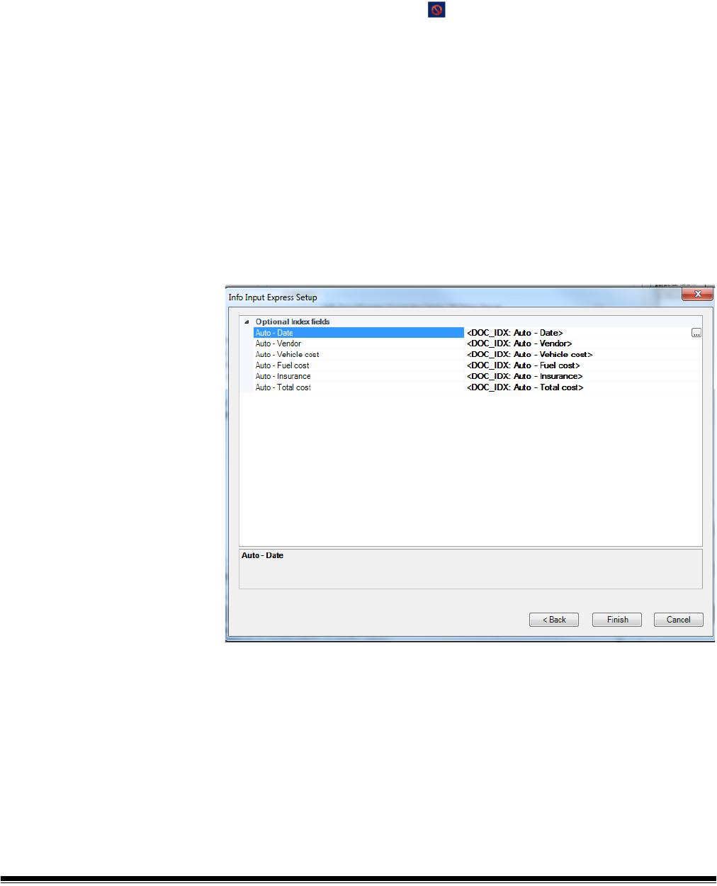
96 A-61750 November 2016
You can add a Default Value by selecting one from the drop-down list. A list of
predefined values, including any defined bar code, OCR or mark detection
zones will be displayed. If you require a more complex default value, select
Edit. You can define the default value using one or more predefined tags or
fixed strings.
The Status column will indicate if there are any issues. Selecting a row
containing the Status indication will display a message in the area below
the Edit button. The status message will describe the problem and how it can
be resolved. The Status symbol indicates that there is a problem creating the
index field that must be resolved before continuing. You can uncheck the
Create Index checkbox if the index field is not needed.
To add or edit other index field parameters such as Output format, Substitute
Characters and List (for drop-down index fields), select the row for the
appropriate index field and click Edit.
Step 3. Selecting value to upload to Info Input Express
Now that you have created index fields, you can use these index fields along
with system values (Job name, Batch name, date, time, etc.), OCR, bar code
mark detection zone values or combinations of these values to populate your
Info Input Express index fields.

A-61750 November 2016 97
By default the index field created in Step 2 is used to populate the Info Input
Express index field. To select a different value, select the index field and click
the More icon at the far right. You can select on or more items from the list,
including fixed text strings enclosed in double quotes. For example “Created:
“<DATE_EEMMYY>.

98 A-61750 November 2016
Kodak Info Activate
Destination Setup
The Kodak Info Activate Solution Destination Setup provides a quick, easy
way of configuring a Capture Pro Software job setup for use with your existing
Kodak Info Activate Solution document management system.
The setup wizard will guide you in connecting to your Info Activate site,
selecting the Info Activate job that will be used to process the documents and
creating the index fields required by Info Activate.
The Info Activate Solution Setup Wizard will guide you through three steps:
Step 1. Info Activate Destination setup: Create, Edit, Select Info Activate
connection
Select a connection to the Kodak Info Activate Solution site. A connection
specifies the Host name, Site name and the Credentials required to access the
site. You may provide a meaningful name to the connection for future use.
If no connections have been defined, the Create a SharePoint connection
dialog box will be displayed.
1. Enter a name for the connection. You will use this name to refer to this
specific Info Activate site.
2. If required, enter the credentials to access the Info Activate site.
3. Enter the Host name. For example: https://my-InfoActivate-Host.
4. Enter the Site name. If the host name and credentials are correct, you can
select Browse to select the available sites.
Step 2. Info Activate Destination setup: Create and Configure index fields
After selecting one of the Info Activate jobs found on your Info Activate site, the
Info Activate columns associated with the job will be displayed.
The Column Type will be shown and the Required checkbox will be checked if
the column is required by your Info Activate job.
By default the Create Index checkbox will be checked for all column types that
may be populated by the automatically created and configured index fields. If
you do not want to populate a specific column or if you do not require a new
index field to populate a specific column, then uncheck the Create Index
checkbox. If you want to create an index field for an Info Activate column that
is not checked, check the Create Index check box and then click Edit to
configure the index field. You will have the opportunity later to specify the data
that is to be stored in a column.
As an example of when to uncheck the Create Index check box imagine that
the Info Activate column Full Name is to contain a persons name in the form
‘last name, first name’. Two existing index fields, ‘First name’ and ‘Last Name’,
will be used to populate this column. The mapping of these two index fields will
be done later. For now uncheck the Create Index check box for the Full Name
column as an index field ‘Full Name’ is not needed.
An ‘Input Format’ will be recommended for each new index field based on the
data requirements of the Info Activate column. You do not need to change the
recommended format unless you want to further restrict the data range or data
type.
A ‘Default Value’ will be shown if a default value has been specified in Info
Activate for the column. Use the drop list to change an existing value or add a
default value. A list of default, predefined values, including any defined bar
code, OCR or mark detection zones will be displayed. If you require a more
complex default value, select Edit to define the default value using one or more
predefined tags or fixed strings.

A-61750 November 2016 99
The Status column indicates if there are any issues in creating an index field.
Selecting a row containing the indication ‘!’ will display a status message in the
area below the Edit button. This symbol indicates that an index field will not be
created for this Info Activate column. In most cases this is because the column
type may not be automatically created by the application. For example the
column type ’calculated’ requires references to other Info Activate columns
that are not known by the application. You can choose to create an index field
for this column by checking the Create Index check box.
Selecting a row containing the ‘!’ indication will display a message in the area
below the Edit button. The status message will describe the problem and how
it may be resolved. This symbol indicates that there is a problem creating the
index field that must be resolved before continuing. You can uncheck the
Create index check box if the index field is not needed.
To add or edit other index field parameters such as Output format, Substitute
Characters and List (for drop down index fields) select the row for the
appropriate index field and select Edit.
Step 3. Info Activate Destination setup: Selecting values to populate
SharePoint
Now that you have created index fields, you can use these index fields along
with system values (Job name, Batch name, date, time, etc.), bar code, OCR
or mark detection zone values, or a combination of these values to populate
your Info Activate columns.
The Info Activate columns that require a value are shown at the top. By default
the index field created in Step 2 is used to populate the column. To select a
different value, select the Info Activate column and select the ‘…’ change icon.
You may select one or more items from the list, including fixed text strings
enclosed in double quotes. For example “Created : “<DATE_DDMMYY>.
Any Info Activate column that was not included in Step 2 (Create Index check
box not checked) will not show a default value. This is because no index field
was created for this column. You may still define a value for this column using
other index fields, system values, OCR, bar code or mark detection zone
values or a combination of these values.
NOTE: Run the setup wizard again, when any future changes are made to the
content type of the Info Activate document library.
Before starting the wizard it is recommended that you create any barcode and
OCR zones that you want to include in the output to Info Activate.
Launch the Info Activate Solution Destination Setup Wizard by:
1. Selecting File>Job Setup.
2. Select the Output tab.
3. Select the Info Activate Solution destination.
4. Select the Info Activate Solution Setup Wizard button at the bottom of
the dialog box.

100 A-61750 November 2016
Advanced options When you select Advanced Options the following options are available:
Auto-Deletion — deletes a front or back image when the image size is lower
than the values specified on the Auto-Deletion dialog box.
Auto-Orientation — analyzes the content of your documents and orients each
document so it is right-reading.
Background Color Smoothing — using this option for documents or forms
with a background color will help produce images with a uniform background
color.
Image Edge Fill — fills unwanted black or white edges on an image, thus
producing a cleaner image.
Image Stamping — stamps the image number on the front and/or back sides
of each page.
Rotate — rotates all images in a batch 0, 90, 180 or 270 degrees as selected.
Stitch — merges all images of a document into a single output file. Images
must be the same width and all but the last image must be the same length.
Split — converts the front and back image into multiple images. Images must
be the same type (color/grayscale or black and white).
To access the image processing options:
1. Click Image Processing under Advanced Options on the Output tab.
2. Select the desired image processing option and configure as desired.
NOTE: The sections that follow provide detailed information about each
option.

A-61750 November 2016 101
Auto-Deletion The Auto-Deletion option allows you to set options for automatically deleting
an image with no content or very busy pages (e.g., the back of a form which
has a lot of explanatory text on it). Auto deletion settings are specified
independently for front and back images.
If you are scanning color, grayscale and/or black and white image types, auto
deletion settings are also set independently. Therefore, you can choose to
delete only the selected image type.
When using Auto-Deletion, it is recommended that you scan some
representative documents which you consider to be blank or almost blank, by
using the Test option. The results of the Test option will help you determine if
you should set the auto delete values using the Image size (byte) is option or
the Image content (%) option.
• Image size (byte) is Above — select this option if you want to delete pages
with a lot of busy, explanatory content on them. For example, if you are
scanning documents with similar content (e.g. insurance forms) on the front
and back page, and the front page has content you need to keep, but the
back page contains instructions on how to file a claim (that you do not need
to keep), enter the number of bytes that you want Capture Pro Software to
delete any image file greater than that amount. Any image that is more than
this value will be considered too large and will be deleted.
• Image size (byte) is Below — select this option if you want to delete pages
with no content or very little content. Enter the number of bytes that Capture
Pro Software will consider the image size to be blank. Any image that is less
than this value will be considered blank and will be deleted
.
• Image content (%) is Above — this option is similar to the Image size
(byte) Above option except that you enter a percentage value that Capture
Pro Software will consider the image to have too much content. Any image
more than this will be deleted
.

102 A-61750 November 2016
• Image content (%) is Below — this option is similar to the Image size
(byte) Below option except that you enter a percentage value that Capture
Pro Software will consider the image to be blank or too little content. Any
image that is less than this value will be considered blank and will be
deleted. Use this setting when there are blank pages.
NOTES:
• When selecting the Image size (byte) option, other factors such as
resolution, compression, etc., will impact the image size.
•The Image content (%) option only looks at the percentage of information
on the image and therefore, is a more consistent and dependable option to
use when images may vary in size, resolution, compression, etc.
Never — click Never, if you do not want to delete any images.
Auto-orientation This option analyzes the content of your documents and orients each
document so it is right-reading.
Auto orientation does not work with all character sets. It is recommended that
you scan some test documents to ensure the document will be oriented
correctly.
• You can select Enable auto-orientation on front or Enable auto-
orientation on back.
NOTE: Auto-orientation will be performed during the output creation
process.

A-61750 November 2016 103
Background color smoothing This option can be used for documents or forms with a background color to
help produce images with a uniform background color.
The smoothing options can be applied to the front and/or back of a page.
You can select a smoothing type of:
None — no background smoothing will be performed; image will not be
changed.
Automatic — the background color(s) will be selected and smoothed
automatically.
Change to White — identifies up to three background colors and substitutes
each one with white. If you select this option, the Apply to drop-down box will
be available allowing you to select:
• Predominant: only the most common background color will be changed to
white.
• Neutral: only the neutral background color(s) will be changed to white.
• All: the background color(s) will be changed to white.
Aggressiveness — controls the amount of variability that can be corrected in
the background color(s). Select a value from 1 to 20.
Before Background Color
Smoothing
After Background Color
Smoothing

104 A-61750 November 2016
Preview — opens the Background Color Smoothing Preview dialog box, which
allows you to compare the original image against the changed image and alter
your settings.
Image Edge Fill This option allows you to fill and clean up the unwanted edges on a scanned
image by covering the area in Black or White (as selected). This option can be
applied to the front and/or back of an image.
You may want to use this option if you have pages with punch holes or ragged
images that you want to clean up.
• Select a value in the Top, Left/Right and/or Bottom area(s) from each side
of the scanned image to be filled in 1/100ths of an inch, or select All sides
match to fill in the same amount on all sides.
NOTE: When using Image Edge Fill, be careful not to enter a value too large
as it could fill in image data that you want to keep.
Original: 3-hole punch without
Image Edge Fill
Image with 37/100
th
of an inch:
fills half of the hole. Value is
not enough.
Image with 62/100
th
of an inch:
fills the entire hole and keeps
all text. Value is good.
Image with 150: fills the entire
hole AND fills some text. Value
is too large.

A-61750 November 2016 105
Image Stamping Image stamping inserts information such as time, date, various sequence
numbers and job or batch name into the scanned image. The Image Stamping
dialog box allows you to place this information at various locations on the front
and/or back of the page. The front and back of a page can be configured
separately.
Front/Back: Stamp string — click Setup to display the Stamp String Setup
dialog box. You can combine one or more items from the list to build a stamp
string formula. For more information, see “Building location and filename
formulas using the Location Setup dialog box” in the “Setup option for File (1)
and File (2)” section earlier in this chapter.
Location: Top or Bottom — places the stamp on the top or bottom of the
image as selected.
Location: Left, Middle or Right — places the stamp on the left, middle or right
of the image as selected.
Margin — select a margin size in 1/100ths of an inch to indicate how far from
the Top, Bottom, Left or Right margin you want the stamp to be placed.
Font size — select the font size of the stamp: 16 or 18 point.
Bold — enable this checkbox for bold print.
Copy front to back — if you want the same setup values on the back as the
values you set up on the front, enable this checkbox.

106 A-61750 November 2016
Setting up a stamp string To setup an image stamp string, do the following:
1. Click Setup on either the Front or Back section. The Stamp String Setup
dialog box will be displayed.
2. Select the items from the list of available Stamp String formulas that you
want to include in your stamp string. For each item you select, click Add
Item.
NOTES:
•The Add leading zeros and Number length fields become available
when you select the following: Document ID, Page Sequence
Number, Image Sequence Number, Image Address Level 1, Image
Address Level 2, or Image Address Level 3. When selecting Page
Sequence Number or Image Sequence Number you will also have
the option to specify when the page or image sequence number should
be reset and the value to which it should be reset.
• To remove an item from the stamp string formula, click Delete Item.
• To delete an entire formula from the stamp string formula, click Delete
Formula.
3. When finished defining your stamp string, click OK.
4. Define the location of the stamp string by specifying the placement of the
image stamp on either side of the page. Margin defines the size of the
border between the text and adjacent page edge(s), either from the right or
left edge horizontally and top or bottom edge vertically. If Middle is
selected, the margin is only applied to the vertical dimension.
5. Select the desired font size: 16 or 18.

A-61750 November 2016 107
6. If bold type is desired, click Bold.
7. Select Copy front to back if you want to duplicate the same stamp string
specified on the front page on both sides, otherwise proceed to setup the
back stamp string.
8. When finished, click OK.
NOTE: Kodak Capture Pro Software makes no attempt to fit text into the
image stamping region. If an image stamp is larger than the allocated
region, excess text will be truncated. Image stamp size is difficult to
predict and depends on the complexity of the formula, font size,
allocated margins and the string itself. It is recommended that a test
scan(s) is performed to be sure that the specified string is not too large
to fit into the stamping region.
Rotate This option allows you to select the desired rotation of 0, 90, 180 or 270
degrees. The degree of rotation applies to all images in the batch.

108 A-61750 November 2016
Stitch When this option is selected, all the images of the document will be merged
into a single, continuous file.
NOTE: To use this effectively, all images must be the same width and length. A
page setup can be used to alter the image width. All images except the
last image must be the same length.
Split When this option is selected, the front and rear image will be converted into
multiple (up to 6) images. Images must be the same type (color/grayscale or
black and white).
Split Page or Image — enable this checkbox to activate the Split option.
Number of resultant images — choose from 2 to 6 images that you want to
split from the drop-down list.

A-61750 November 2016 109
Split image if width is between — use the two drop-down lists to select a
range of widths for the page or image. If the page width falls within this range,
it will be split. If either the front or back side falls outside the range, neither side
will be split.
Front and/or Back — enable this checkbox for Front and/or Back to activate
the split. A graphic will be displayed showing your selection. For example, if
you enable both checkboxes, the two book icons will appear with a red "X" on
each page:
NOTE: When using a simplex-only scanner, only select Front. Selecting both
Front and Back will result in no split.
Output order — the page order will be displayed in this field. Click on each
image segment in the order you want the images to be output. As you click on
an image segment, the red "X" disappears.
Any image segment that is still marked with a red "X" will be deleted and not
sent to output. This option might be useful for the last page of a pamphlet that
is always blank.
Reset Order — any order that you originally specified will be deleted and you
can reorder your images.

110 A-61750 November 2016
Invoke Other
Program option
The Invoke Other Program option on the Output tab allows you to use an
application other than Kodak Capture Pro Software to make changes to your
output. Select the checkbox to enable this option.
Program Name — enter the application name. If needed, click Browse to
search for the application.
Parameters — parameters can be any combination of literal text strings and
variable values which are determined at the time a batch is output. Variable
values are defined by clicking Select.
Literal text strings can be typed into the Parameters text box or in the
Parameter formula window of the Parameter Setup dialog box. Literal strings
should be separated by spaces. Literal strings which include spaces should be
enclosed in double quotes.

A-61750 November 2016 111
To add a variable parameter:
1. Click Select to display the Parameter Setup dialog box to setup variable
parameters.
2. Select the parameter you want to add from the list of Available parameters.
3. Click Add Item.
NOTES:
• You can click Delete Item to delete a parameter from the Parameter
formula, or delete the entire parameter formula by clicking Delete Formula.
• You can also enter literal strings in the Parameter Formula dialog box.
Variable parameters are added to the formula enclosed in <> marks (e.g.
<BATCH_NAME>).
When the batch is output, the actual value will be substituted and the value
passed as a parameter.
For example, the parameter formula <BATCH_NAME> one two "three four"
produces the following four parameters:
/BATCH_NAME=Batch99999
one
two
three four
Omit “/tagname=” identifiers on parameters — by default, parameters will
be passed to the invoked application preceded by a string of the form /
tagname= where tagname identifies the parameter type (e.g. /
BATCH_NAME=Batch001). Selecting this option will omit this identifier and the
program will have to know the number and sequence of passed parameters in
order to interpret them properly.
For example, if Omit “/tagname=” identifiers on parameters was selected,
the formula: <BATCH_NAME> one two "three four" would produce the
following parameters:
Batch99999
one
two
three four

112 A-61750 November 2016
Create output file and send its path as parameter — selecting this option
generates an XML file which contains the parameters. The path to this file will
be passed to the invoked program as the only parameter.
Location — click Setup to specify the path formula and file name for the
output file.
In the XML file, string literals will be in a PARAM_LIST element which contains
one PARAM element per literal.
Variable parameters will be contained in elements which identify the parameter
type (like <BATCH_NAME>).
A schema file KCCustomApplication.xsd (see Appendix D) can be used to
validate resultant XML files and as a reference during code development.
For example, the location and file name formula
<EXPORT_PATH>"\"<BATCH_NAME>"\" and Parameters.XML generated the
parameter C:\BatchesPro\Batch001033841\Parameters.XML.
The Parameters.XML file had the following content:
<?xml version="1.0" encoding="UTF-8" standalone="no" ?>
<KCCustomApplication xmlns:xsi="http://www.w3.org/2001/XMLSchema-instance"
xsi:noNamespaceSchemaLocation="KCCustomApplication.xsd">
<PARAM_LIST>
<PARAM>one</PARAM>
<PARAM>two</PARAM>
<PARAM>three four</PARAM>
</PARAM_LIST>
<BATCH_NAME>Batch001033841</BATCH_NAME>
</KCCustomApplication>

A-61750 November 2016 113
Remote Output
(Network Edition
only)
Remote Output allows you to transfer batches to a Remote Output server for
processing. This is most useful for processing intensive jobs which may slow
down capture operations, such as jobs which produce searchable PDF files.
Remote Output server configuration is contained in a server map which is
configured as part of the Kodak Capture Pro Software installation (see the
Administrator’s Guide for Network Edition).
One or more optional Remote Output servers may be present in a Network
Edition configuration.
A job setup can be configured to always send batches to a particular output
server (Manual Select) or distribute jobs among output servers in a “round
robin” fashion (Auto Select).
•If the Auto Select option is selected, batches will be assigned in rotation to
available output servers. No load balancing will occur.
•If the Manual Select option is selected and the server is “down”, an error
will be returned to the application and the user will have to manually select
another server or change the job setup to Auto Select.
When selecting Remote Output servers, it is important to remember that
servers must be properly configured to process any jobs sent to them. Server
configuration is not within the scope of the Network Edition installation. For
example, if a job uses the Invoke Other Program option, the invoked program
must be installed and configured on the output server. This applies to all types
of output including those which rely on external databases or other System
Output Destinations.

114 A-61750 November 2016
Job Setup:
Scanner-specific
settings
Not all scanners have scanner-specific settings. This section applies only to
scanners that have printing, image addressing, batch, and patch capabilities. If
your scanner requires scanner-specific settings, a KODAK Scanner: iXXX
option will be displayed on the left side of the Capture tab.
Scanner Options The Kodak i5000/i1800/i4000 and i3000 Series Scanners and the Kodak i2900
Scanner provides the Scanner Options box which allows you to access the
TWAIN Datasource and setup Message Configuration and other options (e.g.,
Printing, Image Addressing, Patch, Batch, etc.)
NOTE: Printing, Image Addressing, Batch and Patch options are described in
detail in the Scanning Setup Guide for your scanner. To obtain a copy
of the Scanning Setup Guide, go to: www.kodakalaris.com/go/
docimaging and select your scanner.
Scanner Options
Message Configuration — displays the Message Configuration dialog box.
This dialog box allows you to specify custom text to be included in your print
string. A maximum of 20 characters is allowed. You can have up to six unique
messages per string. The Printer option in the TWAIN Datasource must be
enabled and configured before configuring custom messages in Kodak
Capture Pro Software. See the next section for procedures on customizing
your print string.
New batch starts with counter equal to — enter the number you want to
start a new batch with.
When you click this icon, the TWAIN Datasource will be displayed
allowing you to configure your Printer, Image Address, Batch, Patch,
etc. options. For information and procedures on using the TWAIN
Datasource, refer to the on-line help for the TWAIN Datasource.

A-61750 November 2016 115
Customizing text for your
print string
NOTE: The printer configuration that you set up in Capture Pro Software will
override any printer configuration setup in the TWAIN Datasource.
1. Click Message Configuration. The Message Configuration dialog box will
be displayed.
2. Click Setup for each message you want to configure. The Message Setup
dialog box will be displayed.
3. Select a value from the Predefined values list and click Add Item.
4. Click OK when finished.
NOTE: Click Delete Item to remove the last value in the formula, or Delete
Formula to delete the entire formula.

116 A-61750 November 2016
Kodak i5000 and i1800
Series Scanners
In addition to the Scanner Options previously described, the Kodak i5000
Series Scanners and the Kodak i1800 Series Scanners provide the following
options.
Image Address Options
• Delete level 3 pages: this counter is associated with the numeric portion of
the batch name. Whenever a level 3 page is scanned, Capture Pro Software
will automatically create a new batch and discard the level 3 page.
• Delete level 2 pages: this counter is associated with the document number
of the current batch. Whenever a level 2 page is scanned, Capture Pro
Software will automatically create a new document.
• Set image address on new batch: sets the image address value when a
new batch is manually created in Capture Pro Software. This option does
not affect the image address when batches are automatically created in
Capture Pro Software (e.g., blank page separation, bar code separation). By
default, the image address default value for a new batch will be as follows:
- Fixed field: the default value as defined in this dialog box.
- Level 3: the batch number portion of the Capture Pro Software batch
name (e.g., a value of 19 if the batch name is Batch019).
- Level 2: Capture Pro Software document number for the first document
in the batch.
- Level 1: 0 if the image address format is level 2 or level 3.
1 if the image address format is level 1.

A-61750 November 2016 117
• Set image address on scanner start: automatically resynchronizes the
scanner image address with the current scan batch in Capture Pro Software
every time the scanner is started. The image address value is set to what
the image address should be for the next scanned page. This option is only
available when Set image address on new batch is enabled.
When the scanner image address is resynchronized, the image address
fields will be set to the following:
- Fixed field: will not change from the current scanner value.
- Level 3: the batch number portion of the Kodak Capture Pro Software
batch name.
- Level 2: the current Capture Pro Software document number.
- Level 1: the number of pages in the current document if the image
address format is level 2 or level 3. Number of pages in the current
document + 1 if the image address format is level 1.
NOTE: When simultaneous scanning, Set image address at scanner
start is not recommended. This is because the number of pages
in the current document is not correctly maintained by Capture
Pro Software when simultaneous scanning. As a result, the level
1 portion of the image address can easily get out of sync.
Fixed field value — this is a static field containing ASCII text that does not
increment or change during scanning. Enter the text in the field or click Setup,
which displays the Fixed Field Value Configuration dialog box.
OK — saves your settings and closes the Job Setup dialog box.
Kodak i4000/i3000 Series
Scanners and Kodak
i2900 Scanner
See the section entitled, “Scanner Options” earlier in this section for
information on the Scanner Options box. There are no additional options for
these scanners on this tab.
See the Scanning Setup Guide that supports your scanner to configure Print
options for these scanners.

118 A-61750 November 2016
Kodak i600/i700/i1400/
i200 Series Scanners
This section provides information that is specific to the following scanners:
• Kodak i600 Series Scanners
• Kodak i700 Series Scanners
• Kodak i1400 Series Scanners
• Kodak i200 Series Scanners
The Imprinter tab provides the following options.
Enable imprinter — check this box to enable the imprinting function.
NOTE: The Counter is the document count for the scan session. This value is
incremented sequentially by the scanner and returned in the image
header.
Counter length — allows you to configure the length of the counter from 1 - 9.
However, if for example, you only have six characters left in the print string,
then the length would be limited to 6.
Counter format — allows you to configure the format of the counter when the
width of the value is less than the field width. Select one of the following
formats from the drop-down list:
• Display leading zeros (e.g., “004”)
• Suppress leading zeros (e.g., “ 4”)
• Compress leading zeros (e.g., “4”)
Date Delimiter — select a separator setting from the drop-down list: None,
Forward Slash (2006/08/24), Hyphen (2006-08-24), Period (2006.08.24) or
Blank (2006 08 24).

A-61750 November 2016 119
Font — from the drop-down list, select Large comic, Large cine, Large
comic 180, Large cine 180, Small comic, Small cine, Small comic 180 or
Small cine 180.
Position — select a value to determine how far the printed information will
appear from the leading edge of the document.
Message Configuration — displays the Message Configuration dialog box for
your scanner. This dialog box allows you to specify custom text to be included
in your print string. A maximum of 20 characters is allowed. You can have up to
six unique messages per string.
Print string — enter a print string or click Setup to open the Formula
Configuration dialog box and set up your print string using predefined values.
New batch starts with counter equal to — enter the number you want to
start a new batch with.
Kodak i800 Series
Scanners
This section provides scanner-specific information for the Kodak i810, i820,
i830 and i840 Scanners.

120 A-61750 November 2016
Imprinter tab Enable imprinter — enables the print functionality.
Font — two different character sizes, referred to as Large and Small, are
available. Information is printed on each document in one of the two
orientations: Comic or Cinema. You can choose:
• Large Comic
• Large Cinema
• Small Comic
• Small Cinema
• Large Comic 180
• Large Cinema 180
• Small Comic 180
• Small Cinema 180
Counter format — allows you to configure the format of the counter when the
width of the value is less than the field width. Select one of the following
formats from the drop-down list:
• Display leading zeros (e.g., "004")
• Do Not Display (e.g., "4")
• Display As Spaces (e.g., " 4")
Date Delimiter — select a separator setting from the drop-down list: None,
Slash (2008/08/24), Hyphen (2008-08-24), Period (2008.08.24) or Space
(2008 08 24).
Position — select a value from 0.35 to 33.5 inches to determine how far the
printed information will appear from the leading edge of the document.
• Printing automatically stops 6.3 mm (1/4-inch) from the trailing edge of the
document even if the information has not been completely printed.
• The horizontal print position is set manually on the scanner. See the User’s
Guide for Kodak i800 Series Scanners for information on changing the
horizontal print position.
Counter length — allows you to configure the length of the counter from 1 - 9.
However, if for example, you only have six characters left in the print string,
then the length would be limited to 6.
Date format — select one of the following formats: MMDDYYYY, DDMMYYYY
or YYYYMMDD.
Print string — allows you to define your print string. The maximum amount of
characters for the print string is 40 characters (including spaces).
Select the level of the document that you want the specified print string to be
printed on: Level 1, Level 2 or Level 3. For example, if you use three-level
image addressing, you can print the date on your level 3 document, nothing on
level 2 and the document count on level 1.
Message Configuration — displays the Message Configuration dialog box for
your scanner. This dialog box allows you to specify custom text to be included
in your print string. A maximum of 20 characters is allowed. You can have up to
six unique messages per messages.
Use uniform print string — click this if you want the print string to be the
same on all levels.
NOTE: For information on the Image Address Options see the next section
entitled, “Image Address tab”.
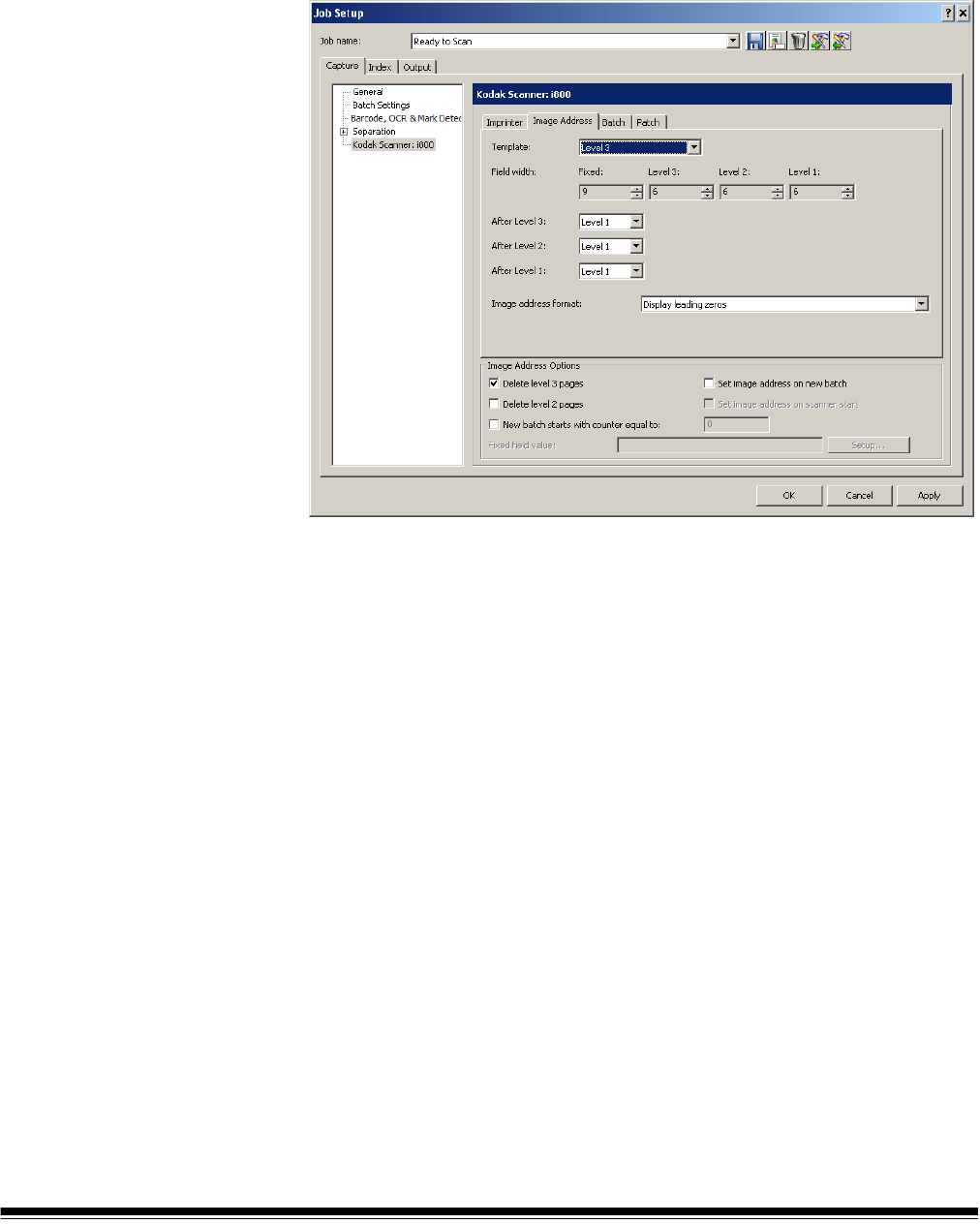
A-61750 November 2016 121
Image Address tab Image addressing allows you to create counters within your job setup for each
batch, document and page. These counters create a unique image address for
each image as it is being scanned. Depending on your settings, the image
address will contain an identification of its batch, its document, and its own
number within the batch, along with a fixed value, such as a date or location
name.
Template — up to four fields can be defined. The maximum length for each
image address field is 9. The combined length of all image address fields
cannot exceed 27 characters. This results in a maximum image address length
of 30 characters (with a period (.) delimiter between each field). Enter a width
value of 0 to disable an image address field. The default setting of all image
fields widths set to 0 will disable image addressing in the scanner.
The i800 Series Scanners have more options available for image addressing
schemes with the following guidelines:
• Only one field may be assigned to a level. You are only allowed one level 1
field, one level 2 field, and one level 3 field.
• There is no requirement to have any level field.
Field width — there are four image address fields that make up the image
address format:
• Fixed — a static field containing ASCII text that does not increment or
change during scanning.
• Level 3 — a counter that is associated with the numeric portion of the batch
name within Capture Pro Software. Whenever a level 3 page is scanned,
Capture Pro Software will automatically create a new batch and discard the
level 3 page.
• Level 2 — a counter that is associated with the document number of the
current batch in Capture Pro Software. Whenever a level 2 page is scanned,
Capture Pro Software will automatically create a new document.

122 A-61750 November 2016
• Level 1 — a counter that is associated with the page number of the current
document in Capture Pro Software. Whenever a level 1 page is scanned,
Capture Pro Software will attach the images for the page to the current
document.
After Level 3, After Level 2, After Level 1 — for each image address level,
specify the image level that will be assigned to the next scanned page.
Possible values are Level 1, Level 2 and Level 3. Level 1 is the default.
For example:
For health claim processing, every page scanned (the claim form) is its own
document. There is, however, the occasional claim form that will be
accompanied by some form of correspondence or supporting documentation.
For this application, you would define a Level 2 image address with the
following rules:
• Level 2 followed by Level 2
• Level 1 followed by Level 1
This will effectively create a new document in Capture Pro Software for every
page scanned. When the exception claim form needs to be scanned, the
scanner operator presses the Level key on the scanner control panel to set
the image address level to Level 1 after scanning the claim form. Then the
corresponding pages are scanned. Once complete, the Level key is pressed
again to set the image address level back to level 2 for regular scanning.
Image Address format — the image address can be printed on the original
documents as they are transported through the scanner. You can define the
format in which the image address is printed. Select one of the following
formats:
• Display leading zeros (e.g., 004.003.002.001)
• Suppress leading zeros (e.g., 004. 3. 2. 1)
• Compress leading zeros (e.g., 004.3.2.1)

A-61750 November 2016 123
Image Address options The Image Address Options appear on all tabs. You can enable the following
options:
• Delete level 3 pages: this counter is associated with the numeric portion of
the batch name. Whenever a level 3 page is scanned, Capture Pro Software
will automatically create a new batch and discard the level 3 page.
• Delete level 2 pages: this counter is associated with the document number
of the current batch. Whenever a level 2 page is scanned, Capture Pro
Software will automatically create a new document.
• New batch starts with counter equal to: sets the sequential counter inside
the scanner whenever a batch is manually created in Capture Pro Software.
This option does not affect the sequential counter when batches are
automatically created in Capture Pro Software (e.g., blank page separation,
bar code separation). When enabled, specify the starting value.
• Set image address on new batch: sets the image address value when a
new batch is manually created in Capture Pro Software. This option does
not affect the image address when batches are automatically created in
Capture Pro Software (e.g., blank page separation, bar code separation). By
default, the image address default value for a new batch will be as follows:
- Fixed field: the default value as defined in this dialog box.
- Level 3: the batch number portion of the Capture Pro Software batch
name (e.g., a value of 19 if the batch name is Batch019).
- Level 2: Capture Pro Software document number for the first document
in the batch.
- Level 1: 0 if the image address format is level 2 or level 3. 1 if the image
address format is level 1.
With sufficient privileges, the user can override the default image address
value when the batch is created.
• Set image address on scanner start: automatically resynchronizes the
scanner image address with the current scan batch in Capture Pro Software
every time the scanner is started. The image address value is set to what
the image address should be for the next scanned page. This option is only
available when Set image address on new batch is enabled.
When the scanner image address is resynchronized, the image address
fields will be set to the following:
- Fixed field: will not change from the current scanner value.
- Level 3: the batch number portion of the Kodak Capture Pro Software
batch name.
- Level 2: the current Capture Pro Software document number.
- Level 1: the number of pages in the current document if the image
address format is level 2 or level 3. Number of pages in the current
document + 1 if the image address format is level 1.
NOTE: When simultaneous scanning, Set image address at scanner
start is not recommended. This is because the number of pages in
the current document is not correctly maintained by Capture Pro
Software when simultaneous scanning. As a result, the level 1
portion of the image address can easily get out of sync.

124 A-61750 November 2016
Fixed field value — specifies the default value for the fixed field portion of the
image address. You can either type in the fixed field value (enclosed in double
quotes “”) or select Setup to access the Fixed Field Value Configuration dialog
box.
The left side of the dialog box contains a list of pre-defined values that you can
use to build the fixed field formula. The fixed field value can consist of one or
more pre-defined values as specified in the formula. The total number of
characters in the formula cannot exceed the defined length for the fixed field.
To set up a fixed field formula:
1. Select a pre-defined value from the list box.
2. Click Add Item.
3. Repeat Steps 1 and 2 until the formula is complete.
NOTE: Select Delete Item to delete the last pre-defined value that was added.
Delete Formula deletes the entire Fixed field formula. You can also
use a special substring syntax, enclosed within square brackets, to
retain a certain portion of a pre-defined value (e.g., [1,4]).

A-61750 November 2016 125
Batch tab Batching is the operation of counting pages or documents. This tab is only
available when the scanner is in Image Address mode.
Enable batch — enables batching and the other options on this tab.
Level — sets the level to count. The options are Level 1, Level 2 and Level 3.
The level you want to count must exist in the image address template as
defined on the Image Address tab.
Size — define the number of documents to be counted prior to beginning the
action to take place when the count has been reached.
Start function — defines the action to be taken prior to processing the first
document in a batch. Options are Level 1, Level 2, Level 3 and None.
End function — select an option of what you want the scanner to do at the
end of a batch:
• Stop feeder and transport
• Continue scan and start new batch
Image Address Options — these options appear on all the tabs. For detailed
information about these options, see the section “Image Address options”
earlier in this section.

126 A-61750 November 2016
Patch tab The Patch tab provides choices of what patch type to recognize. One or more
patches can be selected at a time. The type of patch recognized is returned in
the image header. See the Kodak Alaris publication A-61599, Patch Code
Information for Kodak Document Scanners for complete information.
Enable patch — enables the patch code reader. This option must be checked
to enable any other options on this tab.
Level 2 patch — creates a new document (whether it reads your document
with a patch on it or a Level 2 patch sheet).
Level 3 patch — creates a new batch (whether it reads your document with a
patch on it or a Level 3 patch sheet).
Transfer patch — assigns a patch level to the next document (after the
Transfer patch sheet). Select one of the following options from the drop-down
list: Level 2 or Level 3. The Transfer patch will be treated as Level 0.
Feature patch — Patch Types 1, 4 and 6 can be used by the scanning
application for post-scan image control (they are not used for image
addressing). For example, use these patch types for workflow control or
changing between black and white and color/grayscale imaging.
Toggle patch — use the drop-down list to select which patch heads/readers
you want to use. Each patch head/reader can be turned on and off
independently. The default is for all patch heads/readers to be turned on. This
option is only available when the scanner is in Image Address mode. The
options are: Disabled, Both sides and Front side.
Patch confirmation tone — the confirmation tone signals that the scanner
has recognized a patch. The default is no confirmation tone.
Image Address Options — these options appear on all the tabs. For detailed
information about these options, see the section “Image Address options”
earlier in this section.

A-61750 November 2016 127
Kodak Digital
Science 3520
Scanner
The Kodak 3520 page of the Capture tab on the Job Setup dialog box allows
you to create your printer settings. For more information on your scanner,
consult your scanner User’s Guide.

128 A-61750 November 2016

A-61750 November 2016 129
3 Patch Setup
About patch codes Kodak Capture Pro Software allows you to separate pages and documents on
your scanner with pages containing patch codes. It also allows you to create
attachments to your documents. Before you can use patch code separators,
you must set up your job to recognize patch codes.
Capture Pro Software supports three types of patch codes:
You can define the separation method for each patch code. This is useful for
existing jobs where Patch 2 codes were used as document separator pages
instead of Patch T codes. You can also define a patch code to create an
attachment. For new jobs and for compatibility reasons, it is recommended that
you use patch codes the way they were designed to be used.
• For information on patch code reading when color or grayscale scanning,
see the section entitled, “Using separators when color scanning” in Chapter
4.
• For information on using patch codes on Kodak i800 and i1800 Series
Scanners, see the section entitled, “Job Setup: Scanner-specific settings” in
Chapter 2. When patch code reading is enabled on a Kodak i800/i1800
Series Scanner, patch code reading with Kodak Capture Pro Software is not
allowed. Conversely, when patch code reading is enabled with Kodak
Capture Pro Software, patch code reading on Kodak i800/i1800 Series
Scanners is not allowed.
Patch Type Function Patch kept?
Patch 2 Separates pages into documents yes
Patch 3 Separates documents into batches no
Patch T
(programmable)
Separates pages into documents
Separates documents into batches
Creates an attachment
no

130 A-61750 November 2016
Setting up patch
codes
Patch 2, 3 or T code
separation
The Patch 2, 3 or T separation settings under the Capture tab on the Job
Setup dialog box allow you to set up Kodak Capture Pro Software to recognize
patch codes as separators between batches or documents on your scanner.
Each patch has its separate window, but the commands are the same in all
three windows. You can set up the system to recognize all three patch codes
or just certain ones.
NOTES:
•If the Detect patch check boxes are disabled in all three Patch Code
windows, the patch reader is disabled.
• If you have checked Detect patch on any of the Separation by Patch dialog
boxes, Kodak Capture Pro Software checks each page for the type of patch
code you selected.
Detect patch — when checked, enables the Detect patch option.
• Alternatively search on 180 rotated images — if patch code reading is
unsuccessful, this option rotates the image and searches for the patch code
again. This option helps prevents a patch code read failure because a page
was scanned upside down.
NOTE: The software always searches for patch codes in the first 4 inches
(10 cm) of the top of the image after rotation, deskew, and cropping
(if any). If a patch is vertical, the image should be rotated with the
Software rotation option defined on the Page Setup dialog box.
• Alternatively search on back — if patch code reading is unsuccessful, this
option searches the back side of the document for the patch. If the software
detects a patch code on the front side, it will not look for a patch code on the
back side.

A-61750 November 2016 131
What to do if patch code is detected — select one of these options:
• Batch separation: creates a new batch with a patch code.
- Patch 3 is normally used to create a new batch.
- Typically the page containing a patch code for batch separation should not
have any content. Therefore, the software discards the patch code page;
the next page scanned becomes the first page of the first document in the
batch.
• Document separation: creates a new document with a patch code.
- Patch 2 is normally used to create a new document and keep the image of
the page containing the patch code.
- Patch T is normally used to create a new document and delete the image
of the page containing the patch code.
• Create attachment: creates an attachment with a patch code.
• Delete page: deletes the page containing the patch code that started the
new document or attachment. This option is important when you use inserts
used for document separation purposes that do not contain any other
information.
• Rotate document based on patch: rotates the image containing the patch
code so the patch code is located horizontally on top of the page. All images
in the document will be rotated. This option only works when the
Alternatively search on 180 rotated images option is enabled.
-The Rotate document based on patch option does not work when the
patch code separator page is discarded.
OK — closes the dialog box and saves your settings.
Creating an attachment
with a patch code
1. Select File>Job Setup. The Job Setup dialog box will be displayed.
2. Select the job from the Job Name drop-down list that requires patch code
separation.
3. Open the Capture tab and select Separation>Patch Code.
4. Select the patch type that you want to define: Patch 2, Patch 3 or Patch T.
The Patch Code window will be displayed.
5. Click Detect patch.
6. Under What to do if a patch code is selected, check the Create
Attachment.
7. Check all other desired options in the Patch Code window.
8. Click OK.

132 A-61750 November 2016
Separating batches or
documents with patch
codes
Kodak Capture Pro Software can recognize patch codes as separators
between batches or documents on your scanner.
1. Select File>Job Setup. The Job Setup dialog box will be displayed.
2. Select the job from the Job Name drop-down list that requires patch code
separation.
3. Open the Capture tab and select Separation>By Patch Code.
4. Select the patch type you want to define: Patch 2, Patch 3 or Patch T. The
Patch Code window will be displayed. You can enable as many of the
patch code types as you need.
5. Click Detect patch.
6. If desired, check one or both of the following options: Alternatively search
on 180 rotated images and/or Alternatively search on back.
7. Under What to do if a patch code is selected, check either the
Document Separation or Batch Separation.
8. Check any other desired options.
9. Click OK.

A-61750 November 2016 133
4 Bar Code, OCR and Mark Detection Setup
Overview To use bar codes, OCR zones or mark detection zones for indexing in your job
setup, do the following:
• Select the Page Setup that will be used when scanning into this kind of job.
• Edit the job setup.
• Scan a page to use as a template for defining your bar code, OCR or mark
detection zone.
• Define where on the template image the bar code, OCR or mark detection
zone will be found.
• Specify how a correct bar code, OCR or mark detection zone value will be
recognized.
• Define the page(s) where you want to apply the zones.
In addition to using bar codes or OCR zones for separation in your job setup
you must do the following:
• Set up the actions connected to that bar code or OCR zone (e.g., create a
new batch, create a new document in the current batch or populate one or
more index fields).
This chapter explains these steps, except for populating index fields.
Populating index fields can be found in Chapter 2, Job Setup.

134 A-61750 November 2016
Using bar codes Bar coding is a method of encoding data in a machine-readable code
consisting of a parallel arrangement of dark and light elements. The light
elements are referred to as “spaces” and the dark elements as “bars.” The
bars and spaces are either wide or narrow. The combination of wide and
narrow bars and spaces is a bar code. Each bar code begins with a “start”
character and ends with a “stop” character. The industry uses bar codes to
provide more accurate and efficient data input than is possible using manual
data entry.
Bar code setup allows you to define the:
• name of the bar code
• data mask or syntax
• physical location where to find the bar code (in a zone or anywhere on the
image)
• bar code type (width, height, quality and confidence level)
• level where you can find the bar code (batch, document or page)
• source for capturing the bar code
Follow these tips to maximize the performance of Kodak Capture Pro
Software:
• Choose the Page Setup name that you will use for scanning before you
define a bar code zone.
• Make sure that all glass surfaces (the glass guides or glass over the camera
area) within the scanner transport are clean. Dirty surfaces cause poor read
rates.
• Use a higher resolution to obtain better read rates (300 vs. 200 dpi).
• Check the positioning of the zone around the bar code; it can affect the
confidence level of a bar code. Leave at least a 1/4-inch of space around a
bar code to guarantee that the full bar code will always fall within the zone.
Move the zone around the bar code until the highest confidence rate is
achieved.
• The minimum bar code height specification is 40 pixels. At 200 dpi, 40 pixels
is 20/100
ths
of an inch; at 300 dpi, 40 pixels is 13/100
ths
of an inch. For bar
codes smaller than 40 pixels in height, specify a bar code height in the Bar
Code Zone Setup dialog box.
• Verify that the correct bar code type and bar code orientation are selected in
the Bar Code Zone Setup dialog box.
• If bar codes are on documents with color backgrounds, you may need to
lower the threshold value in the Bar Code Zone Setup dialog box for
improved read rates.
• If possible, use medium or low density bar codes. High density bar codes
may require a lower threshold value in the Bar Code Zone Setup dialog box.
• To achieve better read rates on more difficult bar codes, lower the Quality
level in the Bar Code Zone Setup dialog box.
• When using Anywhere bar code zones, use a PC with a 2.8 GHz processor
or higher. This will ensure Kodak Capture Pro Software’s ability to scan at
scanner rated speeds when bar code reading is enabled.

A-61750 November 2016 135
Bar Code, OCR &
Mark Detection
window
The Bar Code, OCR & Mark Detection window allows you to scan and
manipulate an image and create a bar code zone, OCR zone or mark
detection zone.
To access the Bar Code, OCR & Mark Detection window:
1. Open the Job Setup dialog box.
2. Click Bar Code, OCR & Mark Detection on the Capture tab.
NOTE: Setting eight or more bar code zones for a job may adversely affect
your scanning speed.
Image — if desired, select a pre-existing image from the drop-down list. The
Image drop-down list contains all the images that have been scanned for bar
code setup. You must have at least one image in this list before you can define
a bar code, OCR or mark detection zone.
NOTE: For typical job setups using bar code zones, OCR or mark detection
zones, a single image is all that is required. Multiple images are
needed for job setups that have batch and document header sheets,
each containing bar code, OCR or mark detection information.
Zones — displays the name of a bar code, OCR or mark detection zone.
When you click on one of the zones listed, the image in the display area will
highlight where the zone is located on the image. Any bar code, OCR or mark
detection zone that you defined will be displayed on the current image, even if
you defined those zones using a different image.

136 A-61750 November 2016
Icons
Start/Scan — opens the Scan Image dialog box, which allows
you to enter an Image name and scan an image containing bar
codes, OCR text segments or mark areas.
NOTE: Capture Pro Software will use whatever Page Setup is
currently selected when Start/Scan is selected.
Draw region — allows you to draw a rectangle around a bar
code or OCR text segment or marked area on the scanned
image and then displays the Bar Code Zone Setup, OCR Zone
or the Mark Detection Zone Setup dialog box.
Magnify — enlarges a portion of the image. You can enlarge
any area on the image where you place the Magnify tool and
click and hold.
Pan — allows you to move the image around when the image is
larger than the Bar Code, OCR & Mark Detection window.
Zoom in — zooms in on the image.
Zoom out — zooms out on the image.
Fit window — changes the image display so the image fits the
Bar Code, OCR & Mark Detection window.
Actual size — displays the image at the actual size. One
scanned pixel equals one pixel on the Bar Code, OCR & Mark
Detection window.
Test selected bar code, OCR or Mark Detection zone —
opens the Bar Code, OCR and Mark Detection Values dialog
box, which allows you to view test results on a selected zone.
Test all selected bar code, OCR or Mark Detection zones —
opens the Bar Code, OCR and Mark Detection Values dialog
box, which allows you to view test results on all selected zones.
Create barcode — enables you to create a bar code zone from
the displayed image in the Bar Code, OCR & Mark Detection
window.
Create OCR zone — enables you to create an OCR zone from
the displayed image in the Bar Code, OCR & Mark Detection
window.
Create mark detection zone — enables you to create an mark
detection zone from the displayed image in the Bar Code, OCR
& Mark Detection window.

A-61750 November 2016 137
OK — closes the dialog box and saves your settings.
Bar Code, OCR &
Mark Detection
windows context-
sensitive menu
When you right-click on an image in the Bar Code, OCR & Mark Detection
window, a context-sensitive menu will be displayed. If no bar code, OCR or
mark detection zones are selected, a more limited menu will be displayed.
Cut — removes the selected bar code, OCR or mark detection zone. If you
want, you can paste this bar code, OCR or mark detection to another location
on the same image by left-clicking on the zone and dragging it to the new
location.
Copy — copies the selected bar code, OCR or mark detection. Copy is also
useful when several bar code, OCR or mark detection zones of the exact same
properties (except for location) are required. After defining the first zone, use
the Paste option to duplicate it. After creating each duplicate zone, move it by
left-clicking on the zone and dragging it to the desired location.
Zone properties — opens either the Bar Code Zone Setup,
OCR Zone Setup or the Mark Detection Zone Setup dialog box
which allows you to view the properties of the selected bar code,
OCR or mark detection zone.
Select pages to apply for all zones — opens the Zone Pages
Setup dialog box which allows you to select the page or pages to
apply the defined OCR, bar code and mark detection zones. For
more information see the section entitled, “Zone Pages Setup
dialog box” later in this chapter.
Delete selected zone — allows you to delete a bar code, OCR
or mark detection zone. A confirmation box will be displayed to
verify your choice.

138 A-61750 November 2016
Paste — pastes a copied or cut bar code, OCR or mark detection zone into the
current image. The Paste option appears on this menu only if you have copied
an image or text string into the clipboard. When pasting a bar code, OCR or
mark detection, the zone coordinates from the saved zone are used in
determining the location of the zone. If the pasted zone is in the wrong
location, you can left-click on the zone and move it to the desired location.
Paste is useful in conjunction with Copy when copying bar code zone
properties to another image containing bar codes in the job.
Test Zone and Test All Zones — attempts to read all or the selected bar code,
OCR or mark detection zones for a value. The Bar Code, OCR and Mark
Detection Values dialog box will be displayed.
This dialog box provides the following information:
• Label indicates the name assigned to the bar code, OCR or mark detection
zone on the Bar Code (OCR/Mark Detection) Zone dialog box.
• Type indicates the type of bar code found in the zone. If the zone is an OCR
zone, the Type will be OCR. If the zone is a mark detection zone, the Type
will be Mark Detection.
• Confidence level (in a percentage) of the bar code value found.
• Orientation of the bar code, OCR or mark detection zone
0° represents a horizontal, right-side-up bar code, OCR or mark detection
zone
90° represents a vertical, top to the left bar code, OCR or mark detection
zone
180° represents a horizontal, upside-down bar code, OCR or mark detection
zone
270° represents a vertical, top to the right bar code, OCR or mark detection
zone
• Value of the bar code, OCR or mark detection zone.
• Zone X and Zone Y coordinates of the upper left corner of the bar code,
OCR or mark detection zone. The coordinates are in 1/100ths of an inch and
represent the distance of the zone from the upper-left corner of the image.
• Zone Width and Zone Height of the bar code, OCR or mark detection zone
in units of 1/100ths of an inch.
NOTE: If a bar code, OCR or mark detection value cannot be found for a zone,
the zone is still included in the value list with only the label and zone
coordinates displayed.
Zone Properties — allows you to define the properties for the currently
selected bar code, OCR or mark detection zone. The Bar Code (OCR/Mark
Detection) Zone dialog box will be displayed. See the sections entitled, “Bar
Code Zone Setup dialog box”, “OCR Zone Setup dialog box” or “Mark
Detection Zone Setup dialog box” later in this chapter for more information.

A-61750 November 2016 139
General Properties — allows you define properties that will apply to all bar
code, OCR and mark detection zones. This option is useful when using bar
code header sheets for document separation and indexing that has less
content than the rest of the pages of the document. This option can increase
the performance of scanning into the bar code/mark detection/OCR
application.
When you select this option, the General Bar Code and OCR Properties dialog
box will be displayed.
1. Select the Extract bar codes/OCR from images between checkbox to
activate this option.
2. Enter a value in the minimum bytes field (default 1000 bytes) and the
maximum bytes field (default 100000 bytes). The values entered in these
fields limit the images from which bar codes, OCR or mark detection text
will be read to only those whose size falls between these values.
3. Click OK.
Rename Image — prompts you to rename the currently displayed image.
When naming or renaming an image, choose an image name that is unique to
Kodak Capture Pro Software. A file extension is not required.
NOTE: Special characters such as: “ ? * . < > \ / are not allowed in the image
name.
Delete Image — removes the current image from the job. Before your image is
deleted, a confirmation box will be displayed to verify your choice. If other
images remain in the image list, then the image preceding the deleted image
will be displayed in its place.
Bar code, OCR and mark detection zone definitions are not affected when you
delete an image as long as you have other images on the image list. However,
if the image to be deleted is the last image in the image list, the following
message will be displayed: This is the last image. Deleting this image also
deletes all bar code, OCR or mark detection zones. Do you want to delete
this image?
If you click Yes, all your bar code, OCR or mark detection zone definitions for
the job will also be deleted. An image must exist in the image list in order to
define bar code, OCR or mark detection zones. If you delete the last image,
you also delete all the bar code, OCR and mark detection zones.
Delete Zone — deletes the selected bar code, OCR or mark detection zone. A
confirmation box will be displayed before the zone is deleted.
Delete All Zones — deletes all the bar code, OCR and mark detection zones
that you defined for this job. A confirmation box will be displayed before the
zones are deleted.

140 A-61750 November 2016
Scanning an image
for bar code setup
Kodak Capture Pro Software allows you to separate pages and documents on
your scanner with pages containing bar codes. It also allows you to create
attachments to your documents using these bar code separators.
Before you can use bar codes as separators, you must:
• Scan an image containing the bar codes into Capture Pro Software.
• Draw and select the bar code zones.
• Set up your job for bar code zone separation.
Kodak Capture Pro Software allows you to scan bar code images directly into
the Bar Code window for viewing, defining and editing.
1. Select File>Job Setup. The Job Setup dialog box will be displayed.
2. Select a job setup from the Job Name drop-down list.
3. Open the Capture tab and select Separation>By Bar Code Zones. The
Bar Code window will be displayed.
4. Select the green Start/Scan button. The Scan Image dialog box will be
displayed.

A-61750 November 2016 141
5. Position the original document in the feeder and click Start/Scan. The
image will be displayed in the dialog box. Scan the image as straight as
possible. Your scanner will use the parameters of the current Kodak
Capture Pro Software page setup.
NOTES:
• Any auto-rotation, auto-cropping and deskew settings from the current
template will also be applied to the scanned image before it is displayed.
• If the image is acceptable, enter a name in the Image name field. The
image name should not contain any of the following characters: : “? * . <
> \ / .
• To discard the image, click Cancel.
6. Click OK to save the image.
NOTES:
• Before you can define a bar code, you must save at least one image in the
Image drop-down list.
• You can also transfer an image from the Image Viewer to the Bar Code
window. See the section entitled, “Transferring an image to the Bar Code
window” later in this chapter.

142 A-61750 November 2016
Creating and selecting a
bar code zone
Before you can use a bar code image for indexing or separation to separate
documents or batches, you need to create and select a bar code zone. Bar
code zones are created to indicate where to look for a bar code that satisfies
your bar code zone properties.
1. Select File>Job Setup. The Job Setup dialog box will be displayed.
2. Select a job setup from the Job Name drop-down list.
3. Open the Capture tab and select Separation>By Bar Code Zones. The
Bar Code window will be displayed.
4. Select an image from the Image drop-down list. If you need to scan the
image, click the green Start/Scan icon on the Bar Code window.
NOTES:
• Place the mouse cursor at the top-left corner of the area of the image
where you want to define the location for this bar code zone.
• Bar code zones are specific to a particular job; not a specific image.
Therefore, when you create a new image, Kodak Capture Pro Software
will display the zones that you defined using previous images.
• When drawing the location for a bar code zone, leave a border area of
approximately 1/4-inch around the bar code. This border is often
necessary for successful bar code reading. Bar code zone locations can
overlap.
5. Click the left mouse button and drag the cursor to draw a rectangle around
the area of the bar code. Bar codes defined with the Zone position
selected on the Bar Code Zone Setup dialog box will be enclosed in a red
box while those defined with Anywhere will be enclosed in a blue box.
After you draw the rectangle, the Bar Code Zone Setup dialog box will be
displayed.
6. In the Zone name field, enter a name for the new bar code zone. You must
create a name in order to save the zone.
7. After entering your other settings, click OK to close the dialog box and
return to the Bar Code window. See the next section, “Bar Code Zone
Setup dialog box” for field descriptions.
8. Click OK to save your settings and close the Job Setup dialog box.

A-61750 November 2016 143
Bar Code Zone Setup
dialog box
Use this dialog box to name your bar code zone, describe how to recognize a
valid bar code for this zone and specify any bar code separation.
Zone name — enter the name for your new bar code zone. This name
identifies the bar code and appears in Index setup as BC_[zonename] in the
list of default values. The bar code Label (from the Barcode and OCR Values
dialog box) does not define or identify a Kodak Capture Pro Software index
field.
Side: Front or Back — select whether the bar code is located on the front or
back of an image.
Keep bar codes with mask — use this option when one or more Anywhere
bar code zones are defined. The bar code value is only retained for the defined
zone when it complies with the mask specified in the Keep bar codes with
mask field. This ensures that the bar code values read on a page are assigned
to the correct bar code zone.
This option is also useful when more than one bar code zone is in the same
physical location on a page but have different values and meanings (e.g., a
zone defined for a batch header sheet versus a zone defined for a document
header sheet). To comply with a specified mask, each character of the bar
code value must match the mask syntax for that character’s position in the
mask.
For example, a mask of A<8> will retain a bar code value of up to, but not
exceeding, eight alphabetic characters:
Bar Code Value Retained?
SURGERY Yes
ADMISSION No
if applicable, enter a mask value.

144 A-61750 November 2016
Minimum length — enter a number for the minimum length of the bar code
value. By default, this option is set to the length of the tested bar code value. If
a value is not found or the value is equal to or greater than six characters, the
default will be set to “6.” It is recommended that the minimum length parameter
be set at six characters or fewer to allow Kodak Capture Pro Software to retain
bar code values in cases of a partial reading.
If the Partial Reading option is not required or enabled, then the mask and
minimum length settings can be used in combination to further restrict the
retained bar code values.
For example:
Mask: 9(10)
Minimum bytes: 6
retains bar code values between six and ten digits, while
Mask: 9(10)
Minimum length: 10
retains bar code values only if they are exactly ten digits.
Bar code width and Bar code height — if the bar code has a fixed length or
height, enter these values in 1/100ths of an inch. An entry in one or both of
these fields increases the performance of bar code reading. If one of the
dimensions is variable, enter 0. The default is 0.
Bar code dimensions can vary depending on the amount of skew. Therefore, it
is recommended that you enter these values only when you are sure of the
dimensions of the bar code.
NOTE: You must specify a bar code height for bar codes that are smaller than
40 pixels high (e.g., at 200 dpi, 40 pixels is 20/100
ths
of an inch).
When specifying a bar code width and/or height, the tolerance is ±10%
(e.g., if you specify 20/100
ths
of an inch for the bar code height, any bar code
between 18/100
ths
of an inch and 22/100
ths
on an inch will be detected).
Type — you may also select additional bar code types that will be considered
valid for this bar code zone. Although it is unusual that more than one bar code
type would be found within a zone, it is possible to select multiple bar code
types. For more information on bar code types, see the section entitled, “Bar
Code types” later in this chapter.
The more bar code types you select, the slower your scanning performance.
When you draw a bar code location, Kodak Capture Pro Software searches
the location for all bar code types. When successful, the software sets the bar
code type to the one found. Otherwise, a bar code type is not selected. There
are two exceptions:
• For Code 39 Extended and Code 39 HIBC bar codes, Capture Pro Software
may set the bar code type to Code 39. As a result, you may need to
manually select Code 39 Extended and Code 39 HIBC.
• For MSIPH bar codes, Capture Pro Software may set the bar code type to
MSI. As a result, you may need to manually select MSIPH.

A-61750 November 2016 145
Bar code zone dialog box
(continued)
Verify checksum — check this box if the bar code contains a checksum
character. Checksum characters help ensure the accuracy of bar code
reading. Not all bar code types support checksum verification. Bar code types
that optionally support checksum verification include:
Code 3 of 9
CODABAR
Interleaved 2 of 5
Some bar code types like PDF417, UPC and EAN have a built-in checksum
routine that cannot be disabled.
If you disable Verify checksum for bar codes containing a checksum, the
checksum value (usually the last character of the bar code) will appear in the
bar code value; otherwise, the check digit will remain hidden.
If checksum verification fails during scanning, a bar code value is not
generated, causing Kodak Capture Pro Software index field audits to fail.
Some bar code types, such as Code 128, have mandatory checksum
characters. The code is always present and must be correct for the value to be
read. Other codes such, as Code 39, have optional checksum characters
which then add an additional code when present.
To read invalid Code 128 symbols, you can select the Minimum partial read
characters option. It will report the data characters even if checksum fails. The
invalid checksum will not be returned. When the bar code has an optional
checksum, it will not be validated by the software. It will operate based on the
bar code specification.
Selecting Minimum partial read characters for a bar code with an optional
checksum will return what it finds, whether it is good or bad. There will be
occasions when the bar code returns the correct result but the checksum itself
fails. Since the checksum is implicit, it is not returned and cannot be directly
tested.
Minimum partial read characters — check this box when you want Capture
Pro Software to generate a bar code value, even if a bar code is incomplete. If
this option is checked, enter the minimum number of characters that will be
allowed for a partial read. This is useful for bar codes that are only used for
document or batch separation where the absolute value is less critical.
For indexing purposes, it is recommended that you define field masks and
minimum lengths. Kodak Capture Pro Software will not produce any bar code
value if the bar code is incomplete and the Minimum partial read characters
field is disabled.
NOTE: Minimum partial read characters should not be used when Verify
checksum is enabled, as this may result in a bar code value being
generated when checksum verification fails.
Filtering — when reading barcodes from fax machines or other devices that
may have CCD pixel dropout, applying a filter may help the read rate if bars
are missing pixels. Selecting Filter1 will fill a gap in a bar of 1 pixel. Filter2 will
fill a gap of 2 pixels, etc.

146 A-61750 November 2016
Process bar code by — when set to Auto, the bar code will be read in the
scanner if possible. If the scanner reaches its maximum number of bar codes
or the bar code is not supported in the scanner, then the bar code will be read
by Capture Pro. When set to Capture Pro, the bar code will be read in the
software.
Advantages of reading bar codes in the scanner (Auto):
• Fast — bar codes are read at full scanner speeds.
• Resolution — bar codes are detected at full image resolution (1200 dpi).
Image processing and compression may degrade edges on some scanner
models.
Disadvantages of reading bar codes in the scanner (Auto):
• The scanner can read fewer bar codes per image than Capture Pro
• The scanner reads fewer bar code types than Capture Pro.
Bar code zone dialog box
(continued)
Orientation — select an orientation option from the drop-down list. If your bar
codes all share the same orientation (e.g., all horizontal or all vertical), it is
recommended that you indicate the specific orientation; this will increase bar
code read and scanning performance.
If your bar codes are predominantly in the same orientation (e.g., horizontal)
but may have an occasional bar code in the opposite direction (e.g., vertical) it
is recommended that you use the appropriate "and" orientation (e.g.,
Horizontal and Vertical).
When the bar code zone is first created, Kodak Capture Pro Software
automatically sets the orientation to the orientation of the bar code, if found.
Horizontal is the default.
Confidence — enter a confidence ratio number to restrict what Kodak Capture
Pro Software considers a successful bar code read. For example, the higher
the value you enter, the chance of misreading bar codes will be reduced.
Quality — select a quality setting between Worst and Best. The highest
quality bar codes are printed by a laser printer or pre-printed with an offset
printer. Lower quality bar codes are printed with inkjet or dot-matrix technology.
Depending on the quality of bar codes being scanned, set the Quality level
accordingly. The higher the quality setting, the faster the bar code read
performance.

A-61750 November 2016 147
Position — select Anywhere or Zone.
• Anywhere: when creating a zone for an Anywhere bar code, draw a
location around one bar code somewhere on the page, and select the
Anywhere option. This situation often occurs when bar codes may be found
at unpredictable locations on documents. When looking for Anywhere bar
codes, Kodak Capture Pro Software searches the image from top to bottom
for horizontal and vertical bar codes. This search order is important to
understand if you have more than one Anywhere bar code on a page or
zone.
• Zone: increases bar code reading and scanning performance and is the
default setting.
- Alternatively search on 180° rotated images — can only be used when
the Zone option is enabled. When bar code reading is unsuccessful,
Kodak Capture Pro Software will also look for the zone after rotating an
image 180 degrees. This slows down bar code reading and scanning, but
prevents a bar code read failure because a page was scanned upside
down. The image is not permanently rotated unless the Rotate based on
bar code option is selected.
• Alternatively search on the reverse side — checking this option
increases document/batch separation and indexing accuracy when pages
are accidentally reversed before scanning.
• Rotate based on bar code — Kodak Capture Pro Software can determine
if a bar code is rotated 180 degrees and will rotate the bar code page 180
degrees to display it in the correct orientation. This option is used for
document separation. All of the pages of the document will be rotated in the
same manner as the lead page containing the bar code zone. If required,
only one bar code zone should have the Rotate based on bar code option
enabled.
NOTE: Batch rotation is not supported in Capture Pro Software.

148 A-61750 November 2016
Read all bar codes: when this option is checked and the Position is
Anywhere, all bar codes on the page will be read. The bar code values will be
separated by the ^ character. The order of the values will be the order that the
bar codes were found when searching from left to right and top to bottom on
the page.
Separation — the following options are available:
• Create a new batch — all images after the separation go into a new
document in a new batch.
• Create a new document — all images after separation go into a new
document in the current batch.
• Next page stays in current document — the next page after the
separation remains in the current document.
• Only separate when change in value — the software separates by a
document or batch only if a value changes.
• No separation — select Batch level or Document level for the bar code
zones:
- Bar code is located on: Batch level: bar codes that are located on the
Batch level or that separate batches are available for Batch and Document
indexing. Batch level bar codes are only read when they are present on a
Batch Header page. A Batch Header page exists whenever batch
separation is defined using patch codes or bar codes (at least one bar
code zone in the job is configured for batch separation).
- Bar code is located on: Document level: bar codes that are located on
the Document level or that separate documents are available for Document
indexing. They are not available for Batch indexing.
• Delete Page — select this option to delete the page containing the bar code
that started the new document. This is important when inserts are used for
the purpose of document separation and do not contain any significant
information. The bar code, however, is still available for Document level
indexing.

A-61750 November 2016 149
Zone Pages Setup dialog
box
By default, the bar code (OCR, mark detection) zone(s) will only be applied to
the first page of a document. To read bar codes (extract text or check for
marks) on additional pages use the Zone Page Setup dialog box to select a
specific page or a range of pages. The Zone Page Setup dialog box is
displayed by selecting the Select pages to apply for all zones icon located in
the bottom right corner of the Bar Code, OCR and Mark Detection Job Setup
dialog box. The Zone Pages Setup dialog box allows you to separately select
the page or pages to apply the defined bar code, OCR and mark detection
zones.
Pages to read OCR zones — used to select the page or pages to apply all the
defined OCR zones. Multiple pages may be entered by separating the page
numbers with commas “,”. For example, “3-8”. For each of the defined OCR
zones, the specified page or pages will be checked for valid text. If valid text is
found in the zone, the zone will be assigned the text read. Any valid text within
the zone on a following page will replace any previous text that had been read.
If a document has less pages than the page entered, then the zone value will
remain empty. For example, if a document has 6 pages and the pages to read
is set to “8, 11-15”, the zone value will remain empty even if the first 6 pages
contained valid text within the zone.
If you need to always read the value in the zone on the last page of the
document and the document may contain a variable number of pages, the
asterisk ‘*’ may be used to read every page of the document. The value read
on the last page will be the final value assigned to the zone.
NOTE: If the value on the last page is not readable or valid, then a valid value
on a previous page will be assigned to the zone.
If the Pages to read Bar Code is empty, then none of the OCR zones will be
read.

150 A-61750 November 2016
Pages to read Bar code — used to select the page or pages to apply all the
defined bar code zones. Multiple pages may be entered by separating the
page numbers with commas ‘,’. For example, “1,2,5,6”. A range of pages may
be entered by entering the first page number, a dash ’-‘, and the last page
number. For example, “3-8”. For each of the defined bar code zones, the
specified page or pages will be checked for a valid bar code. If a valid bar code
value is found in the zone, the zone will be assigned the bar code value read.
A valid bar code within the zone on a following page will replace any previous
bar code values that have been read.
If a document has less pages than the page entered, then the zone value will
remain empty. For example, if a document has 6 pages and the pages to read
is set to “8, 11-15”, the zone value will remain empty even if the first 6 pages
contain one or more valid bar codes.
If you need to always read the value in the zone on the last page of document
and the document may contain a variable number of pages, the asterisk ‘*’
may be used to read every page of the document. The value read on the last
page will be the final value assigned to the zone.
NOTE: If the value on the last page is not readable or valid, then a valid value
on a previous page will be assigned to the zone.
If the Pages to read Bar Code field is empty then none of the bar codes zones
will be read.
Pages to read OMR (Optical Mark Recognition) zones — specifying
multiple pages for applying mark detection zones is rarely practical. If the mark
detection zones are defined as “No Frame” then the last page specified in the
page range will determine the value of the mark detection zone. Even mark
detection zones defined as containing a “Frame” may produce poor results.

A-61750 November 2016 151
Separating documents
with bar code zones
Kodak Capture Pro Software allows you to separate documents with bar code
zones within a batch:
1. Select File>Job Setup and select a job and batch.
2. Open the Capture tab and select Separation>By Bar Code Zones. The
Separation by Bar Code Zone window will be displayed.
3. Select an existing bar code zone or define a new bar code zone.
4. Right-click the mouse button to display the context-sensitive menu and
click Zone Properties. The Bar Code Zone Setup dialog box will be
displayed.
5. Under Separation, select Create a new document.
6. Check the Delete page option if you want to delete the page containing the
bar code that started the new document.
7. Fill in the Keep bar codes with mask and/or Minimum length fields if you
want to restrict document separation to a specific bar code value or mask.
8. Select Rotate based on bar code if you want to rotate all pages in the
document in the same orientation as the orientation of the bar code on the
Document Header. Rotating the document based on the bar code does not
work when the bar code separator page is deleted.
For example:
Mask =
”ER”9(8)”-”999 Minimum length = 14: Only bar code values with a
length of 14 characters, starting with the string “ER” followed by eight
numeric characters, a hyphen and three numeric characters start a new
document.
For instance, the patient number bar code on the cover sheet of a folder
starts a new document. The patient number can, in that case, also be used
as a document index. If a bar code in the same zone creates a batch with a
certain value and a document with another value, two zones must be drawn
on top of each other.
9. After entering your other settings, click OK to close the dialog box and
return to the Separation by Bar Code window.
10. Click OK to save your settings and exit the Job Setup dialog box.

152 A-61750 November 2016
Separating batches with
bar code zones
1. Select File>Job Setup. The Job Setup dialog box will be displayed.
2. Select a job setup from the Job Name drop-down list and open the Capture
tab.
3. Select Separation>By Bar Code Zone. The Separation by Bar Code
Zone window will be displayed.
4. Select an existing bar code zone or define a new bar code zone.
5. Right-click the mouse button to display the context-sensitive menu and
click Zone Properties. The Bar Code Zone Setup dialog box will be
displayed.
6. Under Separation, select Create a new batch.
7. Click OK to exit the dialog box and return to the Separation by Bar Code
window.
8. Click OK to save your settings and exit the Job Setup dialog box.
NOTES:
• Bar code zones to be used for batch level indexing are only read when they
are present on a Batch Header page.
• A Batch Header page exists whenever batch separation is defined using
patch codes, bar codes or OCR zones (at least one zone in the job is
configured for Batch separation).
Editing a bar code
zone
1. Select File>Job Setup. The Job Setup dialog box will be displayed.
2. Select a job setup from the Job Name drop-down list.
3. Open the Capture tab and select Separation>By Bar Code Zones. The
Separation by Bar Code Zone window will be displayed.
4. Click on the bar code zone that you want to change, or click on the bar
code zone name in the list on the right side of the Separation by Bar Code
Zone window.
5. Right-click the mouse button to display the context-sensitive menu and
click Zone Properties. The Bar Code Zone Setup dialog box will be
displayed.
6. After you change your settings, click OK to close the dialog box.
7. Click OK to save your settings and close the Job Setup dialog box.
8. After editing a bar code zone, test the bar code to verify that it is still
readable.

A-61750 November 2016 153
Deleting a bar code
zone
1. Select File>Job Setup. The Job Setup dialog box will be displayed.
2. Select a job setup from the Job Name drop-down list.
3. Open the Capture tab and select Separation>By Bar Code Zones. The
Separation by Bar Code Zone window will be displayed.
4. Click on the bar code zone that you want to delete. You can also click on
the bar code zone name in the list on the left side of the Bar Code window.
The zone is highlighted.
5. Click Delete.
6. Click OK to save your settings and close the Job Setup dialog box.
Transferring an
image to the bar code
window
Kodak Capture Pro Software allows you to transfer an image containing bar
codes from the Image Viewer into the Bar Code window for creating bar code
zones.
1. In the Main window, scan your image containing the bar code.
2. Locate and right-click on the image you want to transfer in the Image
Viewer.
3. Select Copy Image to Job Setup. The Copy Image to Job Setup dialog
box will be displayed.
4. Enter the new image name in the Save image as field.
5. Click OK. You can now view the image in the Bar Code window and use it
to create a bar code zone.
You can also directly scan bar code images into the Bar Code window. See the
section entitled, “Scanning an image for bar code setup” earlier in this chapter.

154 A-61750 November 2016
Setting the range for
bar code image size
When you define bar code zones, every page you scan will be checked to see
if it contains those bar codes. This checking can slow scanning performance. If
your bar code pages always have about the same byte count size, and if that
size is different from other pages you scan, you can indicate to the software
that only images within a particular size (byte count) range need to be checked
for bar codes. That setting can speed up scanning performance.
1. Select File>Job Setup. The Job Setup dialog box will be displayed.
2. Select a job setup from the Job Name drop-down list and open the Capture
tab.
3. Select Separation>By Bar Code Zones. The Separation by Bar Code
Zone window will be displayed.
4. Select any image and right-click on a bar code zone. The General Bar
Code and OCR Zone Properties dialog box will be displayed.
NOTE: If a bar code zone does not exist, this option will not be available
until a bar code zone is defined.
5. Check the Extract bar codes/OCR from images between checkbox and
set a range for minimum and maximum byte size.
6. After you make your settings, click OK to close the dialog box and return to
the Bar Code window.
7. Click OK to save your settings and close the Job Setup dialog box. The
new image range is now saved.
8. After editing a bar code zone test the bar code zone to verify that it is still
readable.
NOTE: When scanning both color/grayscale and black and white images,
specify the range of the black and white image.

A-61750 November 2016 155
Creating an
attachment with bar
code zones
1. Select File>Job Setup, select a job and open the Capture tab.
2. Select Separation>By Bar Code Zones. The Bar Code window will be
displayed.
3. Select an existing bar code zone or define a new bar code zone.
4. Right-click the mouse button to display the context-sensitive menu and
click Zone Properties. The Bar Code Zone Setup dialog box will be
displayed.
5. Under Separation, select Next page stays in current document. This
option is only valid for one attachment page. If multiple attachments are
required, then an attachment bar code must be applied to each
attachment. The bar code on the attachment page is not available for
indexing.
6. Check the Delete page option to delete the page (both front and rear)
containing the bar code and to use the next page as the attachment. This is
useful when inserts are applied indicating whether the next page is an
attachment. Any rotation will apply to the next page.
7. Fill in the Keep bar codes with mask and/or Minimum length fields if you
want to restrict attachments to a specific bar code value or mask.
8. Select the Rotate based on bar code checkbox if you want to rotate the
attachment (both front and rear) in the same orientation as the orientation
of the bar code on the page.
9. Click OK to save your settings and close the dialog box.
Testing bar code
zones
When you define a new bar code zone from an image, Kodak Capture Pro
Software automatically checks your zone to verify that it is readable. However,
if you edit the bar code zone or change its properties later, it may no longer be
readable. You can manually test your bar code zones to verify that Capture Pro
Software can still read them.
1. Select File>Job Setup. The Job Setup dialog box will be displayed.
2. Select a job setup from the Job Name drop-down list and open the Capture
tab.
3. Select Separation>By Bar Code Zones. The Bar Code window will be
displayed.
4. Click the Test All Bar Code, OCR & Mark Detection Zones icon to test all
bar codes or click Test Selected Bar Code, OCR & Mark Detection
Zones icon to test an individual bar code zone. The Bar Code, OCR &
Mark Detection Values dialog box will be displayed.
5. After viewing the values in this box, click OK to return to the Bar Code
window.
6. Click OK to save your settings and exit the Job Setup dialog box. All your
bar code zones have now been tested. If you make any changes to the bar
code settings, test them again.

156 A-61750 November 2016
Bar code types Kodak Capture Pro Software supports the following bar code types:
• Airline 2 of 5
•Aztec
• Barcode 32
• CODABAR
• Code 128
• Code 2 of 5 — mutually exclusive with Interleaved 2 of 5
• Code 3 of 9
• Code 39 (no stop start)
• Code 39 Extended
• Code 93
• Data Matrix
• EAN 13
• EAN 8
• Intelligent Mail Barcode
• Interleaved of 2 of 5 — mutually exclusive with Code 2 of 5
• PDF417 — a high-density, two-dimensional bar code type that can contain
up to 1250 bytes of information in a few square inches. With this kind of
density, all index data for a document can be contained in a single bar code.
• Planet (US Post Office Code)
• PostNet (Postal): cannot be selected with any other bar code type
• QR Code
• UCC Code 128
•UPC-A
•UPC-E
Special syntax for two-
dimensional bar codes
When using two-dimensional bar codes, a single bar code can be used to
contain all the index data for a document or batch. To facilitate indexing with
two-dimensional bar codes, a special substring syntax has been added:
<barcode.zonename:[start;length]>
<barcode.zonename:[start;end]>
<barcode.zonename:[# of data elements, delimiter (in single quotes)]>
The delimiter can either be the actual character symbol or its ASCII decimal
numeric value (for symbols that cannot be printed or typed). The delimiter must
be contained in double quotes (“ “).
For example, if a PDF417 bar code contains the following data:
12345678*NURSERY*11/19/1962 the following could be used as default
values for the three index fields of data:
Default Value Actual Value
<BC.PDF417:[1, '*']> 12345678
Returns the 1st element of the bar code string delimited by an asterisk.
<BC.PDF417:[2, '42']> NURSERY
Returns the 2nd element of the bar code string delimited by an asterisk
(42 is the ASCII decimal value for asterisk).
<BC.PDF417:[3, '*']> 11/19/1962
Returns the 3rd element of the bar code string delimited by an asterisk.

A-61750 November 2016 157
Using OCR zones OCR (Optical Character Recognition) is the mechanical or electronic
translation of images of typewritten or printed text (usually captured by a
scanner) into machine-editable text.
OCR setup allows you to define:
• the name of the OCR zone
• the physical location where you find the text (zone location on the image)
• the level where you can find the text (batch or document level)
Use the Bar Code, OCR and Mark Detection Setup function on the Capture tab
on the Job Setup dialog box to set up the bar code reader to read one or more
bar codes or OCR parameters for one or more OCR zones.
The OCR zone separation setting on the Capture tab in the Job Setup dialog
box allows you to scan an image into the Separation by OCR Zone window
and define zones and OCR zone-specific properties.
NOTE: The components of the Separation by Bar Code and Separation by
OCR Zone window, icons and context-sensitive menu are described in
detail in the sections entitled, “Bar Code, OCR & Mark Detection
window” and “Bar Code, OCR & Mark Detection windows - context-
sensitive menu” earlier in this chapter.
OCR indexing uses local language lexicons and allows reading of
alphanumeric text at high speed (1000 characters/second). It is zonal (similar
to bar code reading) and is processed during scanning.
Capture Pro Software supports the following text information for OCR:
- Ligatures (“joined” characters)
- Broken characters
- Degraded characters
- Text from 200-600 dpi resolution
- Text fonts from 8-72 points
- Numbers from 0-9
- Letters from A-Z and a-z
- Symbols ! " $ % & ( ) * + , - . / :, ; < = > ? @ [ \ ] { } £ • ß ´ ª
• For best results, use 300 dpi resolution and 12-point sans serif font (or
larger if using resolutions lower than 300 dpi). Do not use skewed
documents.

158 A-61750 November 2016
• Kodak Capture Pro Software supports a wide range of languages for OCR
indexing. To view a list of these languages:
1. Select File>Job Setup. The Job Setup dialog box will be displayed.
2. Select a job setup from the Job Name drop-down list and open the
Capture tab.
3. Select Separation>By OCR Zones. The Separation by OCR Zone
window will be displayed.
4. Click on any OCR zone and click Zone Properties. The OCR Zone
Setup dialog box will be displayed.
5. Select the language of your text from the available languages on the
Language drop-down list.
Scanning an image for
OCR setup
Kodak Capture Pro Software allows you to separate scanned pages into
batches and documents based on OCR zones. These OCR zones also allow
you to create attachments to your documents.
Before you can use OCR text as separators, you must:
1. Scan an image containing the OCR text into Capture Pro Software.
2. Create and define the OCR zones.
3. Set up your job for OCR zone separation.
To scan an image directly into the Separation by OCR Zone window:
1. Select File>Job Setup. The Job Setup dialog box will be displayed.
2. Select a job setup from the Job Name drop-down list and open the Capture
tab.
3. Select Separation>By OCR Zones. The Separation by OCR Zone window
will be displayed.

A-61750 November 2016 159
4. Position the original document in the feeder and click Start/Scan. The
image will be displayed in the dialog box. Scan the image as straight as
possible. Your scanner will use the parameters of the current Kodak
Capture Pro Software page setup.
NOTES:
• Any settings from the current job setup will also be applied to the
scanned image before it is displayed.
• If the image is acceptable, enter a name in the Image Name field. The
image name should not contain any of the following characters: : “ ? * . <
> \ / .
• To discard the image, click Cancel.
• Before you can define an OCR zone, you must have at least one image
in the Image drop-down list.
• You can transfer an image from the Image Viewer to the Separation by
OCR Zone window. For more information, see the section entitled,
“Transferring an image to the OCR window” later in this chapter.
5. Click OK.

160 A-61750 November 2016
Creating and selecting
an OCR zone
Before you can use an OCR image to separate documents or batches, you
need to create and select an OCR zone.
1. Select File>Job Setup. The Job Setup dialog box will be displayed.
2. Select a job setup from the Job Name drop-down list and open the Capture
tab.
3. Select Separation>By OCR Zones setting. The Separation by OCR Zone
window will be displayed.
4. Select an image from the Image drop-down list. If you need to scan the
image, click the green Start/Scan icon on the Separation by OCR Zone
window.
NOTE: Place the mouse cursor at the top-left corner of the area of the
displayed image where you want to define the location for this OCR
zone. For variable length and height OCR indexing, make sure that
you draw the zone large enough to capture all the indexing data. At
the same time, be careful not to draw the zone so large that stray
data (e.g., lines on a form) are accidentally captured.
OCR zones are job-specific as opposed to image-specific.
Therefore, displaying a new image will continue to display the zones
you defined using earlier images.
5. Click the left mouse button and drag the cursor until a rectangle is drawn
around the text area. After you release the cursor, the OCR Zone Setup
dialog box will be displayed.
6. In the Zone name field, enter a name for the new OCR zone. You must
create a name in order to save the zone.
7. After entering your other settings, click OK to close the dialog box and
return to the Separation by OCR Zone window.
8. Click OK to save your settings and close the Job Setup dialog box.

A-61750 November 2016 161
OCR Zone Setup dialog
box
OCR zones provide Kodak Capture Pro Software with information such as
dimensions of the zone. After you draw an OCR zone, Capture Pro Software
attempts to read the information in the zone and automatically displays the
OCR Zone Properties window with whatever text the software could read in the
zone.
NOTE: The OCR function has difficulty reading italic and underlined
characters on Asian character sets. To increase the OCR reliability, it is
recommended that you use black and white images.
Zone name — enter a name for the OCR zone. You must name the OCR zone
in order to save it.
Side: Front or Back — select whether the OCR zone is located on the front or
back of an image.
Rule for values to keep — any valid Input format text expressions may be
entered or you can leave this field blank. If any Input format text expression is
entered, then only OCR read strings that meet this rule will be kept. For
example, if the expression entered is A<10>, then only OCR read strings
containing 10 or less alpha characters will be kept. For more information see
the section entitled, “Input formats” in Chapter 2.
Search for value in zone — when the Rule for values to keep is a fixed
string format, then the OCR zone read value only needs to contain fixed
strings for a value to be kept.
For example, if the Rule for values to keep was set to Form 1099, then the
following read strings would be valid reads and batch/document separation
would occur if selected.
“77644 Form 1099 - revision 1.2”
“81763 Form 1099 - revision 1.4”
“77644 Form 1099 - revision 2.2”
Character set rule — not applicable at this time.
Primary language —selecting the appropriate primary language ensures that
Kodak Capture Pro Software properly OCR’s special language-specific
characters (e.g., ç or ü). Use the drop-down list to display a list of supported
languages.
Secondary language — one or more secondary languages may be selected
when a zone may contain characters from more than one language.

162 A-61750 November 2016
Custom dictionary — a custom dictionary may be used to improve the
accuracy of recognizing unique or unusual words that appear in your
document set. Click Browse to select a custom dictionary. To build a custom
dictionary, see Appendix D, “Using Custom Dictionaries”.
Separation — the following options are available:
• Create a new batch: all images after the separation go into a new
document in a new batch.
• Create a new document: all images after separation go into a new
document in the current batch.
• Next page stays in current document: the next page after the separation
remains in the current document.
No separation — select one of the following:
• OCR is located on: Document level: OCR zones located on the Document
level and OCR zones that separate documents are available for document
indexing. However, they are not available for batch indexing.
• OCR is located on: Batch level: OCR zones located on the Batch level
and OCR zones that separate batches are available for both batch and
document indexing.
Only separate when change in value — the system separates by document
or batch only if a value changes.
Delete page — delete the page that contains the OCR read value that initiated
the separation.
OK — closes the dialog box and returns to the Separation by OCR Zone
window.
Applying OCR zones to
specific pages
For information on how to select the page or pages to apply all the OCR zones,
see the “Zone Page Setup” earlier in this chapter.
Separating documents
with OCR zones
1. Select File>Job Setup. The Job Setup dialog box will be displayed.
2. Select a job setup from the Job Name drop-down list and open the Capture
tab.
3. Select Separation>By OCR Zones. The Separation by OCR Zone window
will be displayed.
4. Select an image from the Image drop-down list. If you need to scan the
image, click the green Start/Scan icon on the Separation by OCR Zone
window.
NOTE: Use your mouse to draw the OCR zone. The OCR Zone Setup
dialog box will be displayed.
5. Under Separation, click the Create a new document option.
6. Click OK to exit the dialog box and return to the Separation by OCR Zone
window.
7. Click OK to save your settings and exit the Job Setup dialog box.
NOTE: A Batch Header page exists whenever batch separation is defined
using patch codes, bar codes or OCR zones (at least one zone in
the job setup is configured for Batch separation).

A-61750 November 2016 163
Separating batches with
OCR zones
1. Select File>Job Setup. The Job Setup dialog box will be displayed.
2. Select a job setup from the Job Name drop-down list and open the Capture
tab.
3. Select Separation>By OCR Zones. The Separation by OCR Zone window
will be displayed.
4. Select an image from the Image drop-down list. If you need to scan the
image, click the green Start/Scan icon on the Separation by OCR Zone
window.
5. Use your mouse to draw the OCR zone. The OCR Zone Setup dialog box
will be displayed. If you define an area on an image for OCR batch
separation, that area should remain blank on all the other pages in the
batch.
6. Under Separation, click the Create a new batch option.
7. Click OK to exit the dialog box and return to the Separation by OCR Zone
window.
8. Click OK to save your settings and exit the Job Setup dialog box.
NOTE: Batch level OCR zones are only read when they are present on a
Batch Header page. A Batch Header page exists whenever batch
separation is defined using patch codes, bar codes or OCR zones (at
least one zone in the job setup is configured for Batch separation).
For information about separating batches with color/grayscale scanning, see
“Using separators when color scanning” later in this chapter.

164 A-61750 November 2016
Editing OCR zone
properties
1. Select File>Job Setup. The Job Setup dialog box will be displayed.
2. Select a job name from the Job Name drop-down list and open the Capture
tab.
3. Select Separation>By OCR Zones. The Separation by OCR Zone window
will be displayed.
4. Click on the OCR zone that you want to change, or click on the OCR zone
name in the list on the left side of the Separation by OCR Zone window.
5. Right-click the mouse button to display the context-sensitive menu and
click Zone Properties. The OCR Zone Setup dialog box will be displayed.
6. After you change your settings, click OK to close the dialog box and return
to the Separation by OCR Zone window.
7. Click OK to save your settings and exit the Job Setup dialog box.
After editing an OCR zone, test the OCR zone to verify that it is still readable.
Deleting an OCR
zone
1. Select File>Job Setup. The Job Setup dialog box will be displayed.
2. Select a job setup from the Job Name drop-down list and open the Capture
tab.
3. Select Separation>By OCR Zones. The Separation by OCR Zone window
will be displayed.
4. Click on the OCR zone that you want to delete. You can also click on the
OCR zone name in the list on the left side of the Separation by OCR Zone
window. The zone is highlighted.
5. Click Delete.
6. Click OK.
Transferring an
image to the OCR
window
You can scan an image containing text for OCR directly into the Image Viewer
and then transfer it to the Separation by OCR Zone window to create an OCR
zone.
1. Scan your image containing the OCR text.
2. Locate the image in the Image Viewer and right-click on it.
3. Select Copy image to job setup. The Copy Image to Job Setup dialog
box will be displayed.
4. Enter the new image name in the Save image as field.
5. Click OK.

A-61750 November 2016 165
Setting the range for
OCR image size
Sometimes an OCR image is too small to be a readable image. You can set an
image range size to exclude images that are too small.
1. Select File>Job Setup. The Job Setup dialog box will be displayed.
2. Select a job setup from the Job Name drop-down list and open the Capture
tab.
3. Select Separation>By OCR. The Separation by OCR Zone window will be
displayed.
4. Select any image and right-click on the OCR zone. The General Bar Code
and OCR Zone Properties dialog box will be displayed.
NOTE: If an OCR zone does not exist, this option will not be available until a
OCR zone is defined.
5. Check the Extract bar codes/OCR from images between checkbox and
set a range for minimum and maximum byte size.
6. After you make your settings, click OK to close the dialog box and return to
the Separation by OCR Zone window.
7. After editing an OCR zone, test your OCR zone to verify that it is still
readable.
Creating an
attachment with OCR
zones
Creating attachments is useful in jobs where typically every page is a
document (e.g., transaction documents, such as; checks, airline tickets,
invoices, etc.), but there is occasionally a page (such as a corresponding
memo) that needs to be appended to a document.
1. Select File>Job Setup. The Job Setup dialog box will be displayed.
2. Select a job name from the Job Name drop-down list and open the Capture
tab.
3. Select Separation>By OCR Zones. The Separation by OCR Zone window
will be displayed.
4. Select an image from the Image drop-down list. If you need to scan the
image, click the green Start/Scan icon on the Separation by OCR Zone
window
5. Using the cursor, define the OCR zone on the image where you expect to
find the OCR text. The area defined for the OCR attachment should be
blank on all other pages in the batch. The OCR Zone Setup dialog box will
be displayed.
6. Under Separation, select Next page stays in current document. This
option is only valid for one attachment page. If multiple attachments are
required, then an attachment OCR zone must be applied to each
attachment. The OCR zone on the attachment page is not available for
indexing.
7. Check Delete page to delete the page (both front and rear) containing the
OCR zone and to use the next page as the attachment. This is useful when
inserts are applied indicating whether the next page is an attachment.
8. Click OK to save your settings and close the dialog box.

166 A-61750 November 2016
Testing OCR zones When you define a new OCR zone from an image, Kodak Capture Pro
Software automatically checks your zone to verify that it is readable. However,
if you edit the OCR zone or change its properties later, it may no longer be
readable. You can manually test your OCR zones to verify they are still
readable.
1. Select File>Job Setup. The Job Setup dialog box will be displayed.
2. Select a job setup from the Job Name drop-down list and open the Capture
tab.
3. Select Separation>By OCR Zones. The Separation by OCR Zone window
will be displayed.
4. Click the Test All Bar Code, OCR & Mark Detection Zones icon to test all
OCR zones or click Test Selected Bar Code, OCR & Mark Deletion Zone
to test an individual OCR zone. The Bar Code, OCR & Mark Detection
Values dialog box will be displayed.
5. After viewing the values, click OK to return to the Separation by OCR Zone
window.
6. Click OK. If you make any changes to the OCR zone settings, test them
again.
Using separators
when color scanning
Kodak Capture Pro Software can scan color, grayscale, and black and white
images with separators (bar code zones, OCR zones or patch codes). Images
can be separated or mixed together. To separate these color/grayscale images
quickly and reliably, Capture Pro Software uses their duplicate black and white
images for reading the separators.
When scanning both color/grayscale and black and white images and the
software detects a bar code zone, patch code or OCR zone, the software
either deletes all four page images (color front, color back, black and white
front, and black and white back) or attaches them to the new or current
document or batch. This action will be determined by the settings in the Bar
Zone Code Setup dialog box, Patch Code setup, or OCR Zone Setup dialog
box.
When you are scanning only color/grayscale images, the software reads the
duplicate black and white images. While these black and white images are
never displayed or outputted, they are used for bar code reading, patch code
reading and OCR indexing.

A-61750 November 2016 167
Setting up a color
image for bar code/
OCR zones
Kodak Capture Pro Software is capable of using color or grayscale images as
a source for bar codes or OCR text. However, the performance and reliability
of Capture Pro Software will be enhanced if you use a black and white image
as a source.
1. Select Capture>Page Setup List. The Page Setup List dialog box will be
displayed.
2. Select a simultaneous scanning page setup from the list (e.g., Color and
Black & White - 200 DPI - Delete Blanks).
3. Place the color/grayscale original in the scanner and click the green Start/
Scan icon. The images will be displayed in the Image Viewer.
4. Select the black and white image containing bar codes and OCR zones
and click the right mouse button to display the Image context-sensitive
menu.
5. Select Edit>Copy Image to Bar Code/OCR setup. The Copy Image to Job
Setup dialog box will be displayed.
6. Enter the new image name in the text box and click OK.
7. Click File>Job Setup. The Job Setup dialog box will be displayed.
8. Open the Capture tab and select either Separation>By Bar Code Zones
or Separation By OCR Zones. Depending on your selection, the
Separation by Bar Code or Separation by OCR Zone window will be
displayed.
9. The new image name will be displayed in the Image drop-down box.
Follow the procedures for defining a bar code zone or OCR zone described
in the previous chapter.
10. Click OK.

168 A-61750 November 2016
Bar Code and OCR
Disclaimers
Copyright 2000-2011, AllMyPapers, All Rights Reserved.
This product includes OmniPage/-E OCR software © 1995-2012 Nuance
Communications, Inc. All Rights Reserved.
The following OCR, mark detection and bar code-related disclaimer conditions
apply to Kodak Capture Pro Software.
Although the product uses state-of-the-art OCR, mark detection and bar code
technology, accurate recognition under all conditions cannot be guaranteed.
All software and documentation are delivered as such without any express or
implied warranty of OCR, mark detection and bar code recognition accuracy.
Kodak Alaris Inc. and its suppliers shall not be liable for any direct or indirect
misuses and or damages subsequent to illegal use or infringement caused by
the user in modifying, copying, reproducing, or translating any part of
information retrieved with OCR, mark detection and bar code recognition
technologies in Kodak Capture Pro Software.
Using Mark Detection
zones
Mark Detection is a method of detecting the presence or absence of an ink
mark within a specific area that is used to convey some intended information.
Good document design and clear instructions to respondents are very
important in getting high accuracy. Printing model samples of ideally filled and
filled-in-error checkboxes in the instructions is recommended. Respondents
should be urged to fill in the document with a dark blue or black pen. Pencils
are to be avoided, as are pens with an ink color close to a dropout color if the
form is color is dropped during scanning.
Mark Detection setup allows you to define:
• The name of the Mark Detection zone.
• The physical location where you will find the mark (zone location on the
image).
• The value when a mark is detected.
• The value when a mark is not detected.
• If the mark is contained within a frame such as a box or circle.
• The sensitivity to distinguish a mark due to random dirt or scratch “noise”.
• A group of mark detection zones to return a single set of values.
Use the Bar Code, OCR and Mark Detection Setup option on the Capture tab
in the Job Setup dialog box to setup the mark detection parameters for one or
more Mark Detection zones.
NOTES:
• Batch and document separation is not provided for Mark Detection
zones.
• For best results, use 300 dpi resolution images.

A-61750 November 2016 169
Scanning an image for
Mark Detection setup
Kodak Capture Pro Software allows you to capture and save the status of a
mark area or a group of mark areas.
To use Mark Detection:
• Scan an image containing the mark areas into Capture Pro Software.
• Draw and select the mark detection zones.
• Setup optional groups of mark detection zones.
Kodak Capture Pro Software allows you to scan mark detection images
directly into the Mark Detection window for viewing, defining and editing.
1. Select File>Job Setup. The Job Setup dialog box will be displayed.
2. Select a job setup from the Job Name drop-down list.
3. Open the Capture tab and select Bar Code, OCR and Mark Detection.
The Mark Detection window will be displayed.
4. Select the green Start/Scan button. The Scan Image dialog box will be
displayed.
5. Position the original document in the feeder and click Start/Scan. The
image will be displayed in the dialog box. Scan the image as straight as
possible. Your scanner will use the parameters of the current Kodak
Capture Pro Software page setup.
NOTES:
• Any auto-rotation, auto-cropping and deskew settings from the current setup
will be applied to the scanned image before it is displayed.
• If the image is acceptable, enter a name in the Image name field. The image
name should not contain any of the following characters: : “ ? . < > \ /.
• To discard the image, click Cancel.
• Before you can define a mark detection zone, you must have at least one
image in the Image drop-down list.
• You can also transfer an image from the Image Viewer to the Mark Detection
window. See the section entitled, “Transferring an image to the Mark
Detection window” later in this chapter.
6. Click OK to save the image.

170 A-61750 November 2016
Creating and selecting a
Mark Detection zone
Before you use a mark detection image for indexing, you need to create and
select one or more mark detection zones. Mark detection zones are created to
indicate where to look for a mark. Multiple mark detection zones may be
grouped to populate a single index field.
1. Select File>Job Setup. The Job Setup dialog box will be displayed.
2. Select a job setup from the Job Name drop-down list and open the Capture
tab.
3. Select Bar Code, OCR and Mark Detection. The Bar Code, OCR & Mark
Detection window will be displayed.
4. Select an image from the Image drop-down list. If you need to scan an
image, click the green Start/Scan icon on the Bar Code, OCR & Mark
Detection window.
• Place the mouse cursor at the top-left corner of the area of the image
where you want to define the location for this mark detection zone.
• When drawing a zone around a mark detection area that contains a
frame for the mark (box, circle, ellipse, etc.) leave a border area of
approximately ¼-inch around the frame.
• When drawing a zone around a mark detection area that does not
contain a frame (a blank area or line is provided for the mark) make
sure that characters or other elements of the image are not in the zone.
5. Click the left mouse button and drag the cursor until a rectangle is drawn
around the mark area. After you release the cursor, the Mark Detection
Zone Setup dialog box will be displayed.
6. In the Zone name field enter a name for the new mark detection zone. You
must create a name in order to save the zone.
7. After entering your other settings, click OK to close the dialog box and
return to the Mark Detection window. See the next section, “Mark Detection
Setup dialog box” for field descriptions.
8. Click OK to save your settings and close the Job Setup dialog box.

A-61750 November 2016 171
Editing a mark detection
zone
1. Select File>Job Setup. The Job Setup dialog box will be displayed.
2. Select a job setup from the Job Name drop-down list.
3. Open the Capture tab and select Bar Code, OCR & Mark Detection. The
Bar Code, OCR & Mark Detection Zone window will be displayed.
4. Click on the mark detection zone that you want to change.
5. Right-click the mouse button to display the context-sensitive menu and
click Zone Properties. The Mark Detection Zone Setup dialog box will be
displayed.
6. After you change your settings, click OK to close the dialog box.
7. Click OK to save your settings and close the Job Setup dialog box.
8. After editing a mark detection zone, test the mark detection zone using the
Test Selected Bar Code, OCR or Mark Detection zone function.
Deleting a mark
detection zone
1. Select File>Job Setup. The Job Setup dialog box will be displayed.
2. Select a job setup from the Job Name drop-down list.
3. Open the Capture tab and select Bar Code, OCR & Mark Detection. The
Bar Code, OCR & Mark Detection Zone window will be displayed.
4. Click on the mark detection zone that you want to delete.
5. Click Delete.
6. Click OK to save your settings and close the Job Setup dialog box.

172 A-61750 November 2016
Transferring an image to
the Mark Detection
window
Kodak Capture Pro Software allows you to transfer an image containing mark
detection zones from the Image Viewer into the Mark Detection window for
creating mark detection zones.
1. In the Main window, scan your image containing the mark or marks.
2. Locate and right-click on the image you want to transfer in the Image
Viewer.
3. Select Copy Image to Job Setup. The Copy Image to Job Setup dialog
box will be displayed.
4. Enter the new image name in the Save image as field.
5. Click OK. You can now view the image in the Mark Detection window and
use it to create a mark detection zone.
You can also directly scan mark detection images into the Mark Detection
window. See the section entitled, “Scanning an image for mark detection
setup” earlier in this chapter.

A-61750 November 2016 173
Mark Detection Zone
Setup dialog box
Use this dialog box to name your mark detection zone, describe how the mark
is detected and optionally group multiple zones to produce a single result.
Zone name — enter the name for your new mark detection zone. This name
identifies the mark area and appears in the Index setup as MD_(zonename) in
the list of default values.
Filled value — the zone will return this value when it is detected to be “filled”.
The value may be a single value such as “1” or a multi-character value such as
“This checkbox was marked”. The value may also be left empty.
If the zone is added to a group of mark detection zones, this value is included
in the value returned by the zone group. See the section entitled, “Mark
Detection Zone Group Setup” later in this section.
Unfilled value — the zone will return this value when it is detected to be
“unfilled” or empty. The value may be a single value such as “0” or a multi-
character value such as “This checkbox was not marked”. The value may also
be left empty.
If the zone is added to a group of mark detection zones, this value is not used.
The unfilled value returned by a group of zones is defined in the group setup.
See the section entitled, “Mark Detection Zone Group Setup” later in this
section.
Side: Front or Back — select whether the mark area is located on the front or
back of an image.

174 A-61750 November 2016
Frame: Frame or No Frame — a frame can be a rectangle, a circle, an ellipse,
etc.; in which the mark is expected to be placed. The dimensions of the frame
should be at least 50 pixels in each direction, 4 mm (0.2 inch) in the case of
300 dpi resolution.
•If Frame is selected, it may be filled in by any shape such as an X, a tick,
non-solid hatching, horizontal or vertical lines, etc. The recommended filling
shape is an X or a tick. A small number of contiguous black pixels within the
frame area will lead to a value of “filled” for the mark detection zone.
•If No Frame is selected, then any mark of several contiguous black pixels
will lead to a value of ”filled” for the mark detection zone. If the form
contains frames for the mark but the frame will be color dropped then the No
Frame option should be selected.
Mark sensitivity: Low to High — for well-printed, high quality forms, the
sensitivity should be set to High. When High is selected, small marks of just a
few contiguous black pixels will lead to a value of “filled”. For poor quality
forms, a lower sensitivity will allow speckles or visible paper fibers to be
ignored resulting in successful processing.
Add zone to group — select this option if this mark detection zone is
associated with other mark detection zones and a single result is desired for
the group of associated zones. For example, a form presents a question with
three check boxes, “Like”, “Dislike” and “Do not care”. Three mark detection
zones are defined, one for each possible response. All three mark detection
zones would have this option selected and be added to the same group.
Applying mark detection
zones to specific pages
For information on how to select the page or pages to apply all the mark
detection zones, see the “Zone Page Setup” earlier in this chapter.
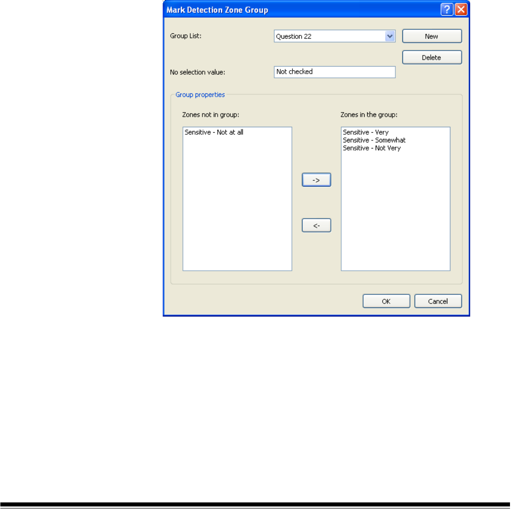
A-61750 November 2016 175
Mark Detection Zone
Group Setup
For each expected mark on a page, a mark detection zone is created and
configured as described in the section entitled, “Mark Detection Zone Setup”.
Each mark detection zone will return a value depending on if the mark area is
“filled” or “unfilled”. This works well for simple “Yes” or “No” questions. For a
question with multiple possible responses, where a single response is desired,
the mark detection zones may be “grouped”.
For example, the question, “When traveling by air, what is your seating
preference?” may have three possible responses, “Aisle”, “Window” or “Do not
care”. Three mark detection zones would be created, one for each of the three
possible responses. The three mark detection zones would all be added to a
new mark detection group. A single index field would be created for the
response to this question and the mark detection group would be used as the
default value for the index field. See the section entitled, “Adding a document
index field” in the Job Setup – Index tab section in Chapter 2.
To add a mark detection zone to group:
1. Select Add zone to group. A list of existing mark detection groups will be
displayed. Select the group in which you want to add this mark detection
zone.
• If there is no existing mark detection group, the Create New Zone Group
dialog box will be displayed.
• Enter a name for the new group and click OK.

176 A-61750 November 2016
2. Select Add/Edit Group. The Mark Detection Zone Group dialog box will
be displayed.
• Group List — shows the name of the current mark detection group.
Click the drop-down list to display other mark detection groups.
• No selection value — the group will return this value if no mark is
detected in any of the mark detection zones within the group. The value
may be a single value such as “0” or a multi-character value such as
“No selection”. The value may also be left empty.
• Group properties — using the -> button, select and move the mark
detection zones that you want to include in the group, from the Zones
not in group list to the Zones in the group list.
3. Using the <- button, select and move the mark detection zones that you do
not want to include in the group, from the Zones in the group list to the
Zones not in group list.
4. Click OK.

A-61750 November 2016 177
5 Page Setup
Page Setup dialog
box
Use the Page Setup dialog box to define image scanning parameters,
automatically delete images, split images or merge images.
To access Page Setup click File>Page Setup.
Page setup name — select an existing Page Setup from the drop-down list.
Icons
Add: displays the Save As dialog box, which allows you to add a
new page setup.
Rename: displays the Rename dialog box which allows you to
rename the currently selected page setup.
Delete: displays a confirmation box which allows you to delete
the selected page setup.

178 A-61750 November 2016
Image tab — allows you to define the way images will be displayed after
scanning.
Auto Delete tab — allows you to automatically delete a scanned image if it
exceeds the settings entered on this tab.
Split tab — allows you to automatically split a scanned image if it exceeds a
certain width.
Merge tab — allows you to merge the front and back images of a scanned
page into a single image.
Intelligent QC tab — allows you to setup the following options to be applied
during image processing: auto-orientation, binarize and hole fill.
OK — saves your settings and closes the dialog box.
Cancel — closes the dialog box without saving any changes.
Apply — accepts the changes made in the dialog box without closing the
dialog box.
Image tab The Image tab allows you to set up scanning parameters and make changes to
your images before they are stored.
Settings — when you click Settings, the TWAIN Datasource will be displayed
allowing you to configure your scan settings. For more specific scanner
information, see the User’s Guide for your scanner.
Display settings prior to scanning — opens the TWAIN Datasource after
you click the green Start/Scan icon.
Flatbed delay — sets a timed delay between scans so the operator can open
a different page on a book or magazine and place it back on the flatbed. Select
the number of seconds for the delay from the drop-down list.

A-61750 November 2016 179
Software rotation — automatically rotates the image after scanning. Select
None, 90, 180 or 270 degrees. As you enter a different setting, the icon will
display how the image would look after rotation.
NOTE: Setting up this rotation in the TWAIN Datasource may yield better
scanning performance than using Software rotation on the Image tab.
2-sided mode — select Classic or Calendar mode from the drop-down list for
two-sided scanning and the corresponding icon will be displayed. Compare
your original image with the icon to determine if it has a classic or calendar
layout.
• Classic: typically used for multi-page reports. The 2-sided mode option
only influences the way the front image is rotated in relation with the back
image. It does not set the overall rotation of the document (0
, 90, 180 or
270
).
When using Classic: 2-sided mode, the front and rear images correspond
as follows:
A 0
rotated front results in a 0 rotated back.
A 180
rotated front results in a 180 rotated back.
A 90
rotated front results in a 270 rotated back.
A 270
rotated front results in a 90 rotated back.
• Calendar: typically used for presentation handouts, financial reports, wall
calendars, etc. The 2-sided mode option only influences the way the front
image is rotated in relation with the back image. It does not set the overall
rotation of the document (0
, 90, 180 or 270).
• When using the Calendar: 2-sided mode, the front and rear images
correspond as follows:
A 0
rotated front results in a 180 rotated back.
A 180
rotated front results in a 0 rotated back.
A 90
rotated front results in a 90 rotated back.
A 270
rotated front results in a 270 rotated back.
Image order — select an image and use Move Up or Move Down to change
the image order listed in the box.
Overcrop — enable this checkbox to trim all edges of the image by the
amount you specify in 1/100ths of an inch.
OK — saves your settings and closes the dialog box.
Cancel — closes the dialog box without saving any changes.
Apply — accepts the changes made in the dialog box without closing the
dialog box.

180 A-61750 November 2016
Auto Delete tab The Auto Delete tab allows you to set options for automatically deleting an
image. You may want to delete images with no content, or possibly very busy
pages (e.g., the back of a form which has a lot of explanatory text on it). Auto
deletion settings are specified independently for front and back images.
If you are doing simultaneous scanning of color, grayscale and/or black and
white image types, auto deletion settings are also set independently.
Therefore, you can choose to delete only the selected image type.
When using Auto Delete, it is recommended that you scan some
representative documents which you would want to delete by using the Test
option. The results of the Test option will help you determine if you should set
the auto delete values using the Image size (byte) is option or the Image
content (%) option. For more information see the next section “Testing your
settings”.
• Image size (byte) is Above — select this option if you want to delete pages
with a lot of busy, explanatory content on them. For example, if you are
scanning documents with similar content (e.g. insurance forms) on the front
and back page, and the front page has content you need to keep, but the
back page contains instructions on how to file a claim (that you do not need
to keep), enter the number of bytes that you want Capture Pro Software to
delete any image file greater than that amount. Any image that is more than
this value will be considered too large and will be delete
d.
• Image size (byte) is Below — select this option if you want to delete pages
with no content or very little content. Enter the number of bytes that Capture
Pro Software will consider the image size to be blank. Any image that is less
than this value will be considered blank and will be deleted.

A-61750 November 2016 181
• Image content (%) is Above — this option is similar to the Image size
(byte) Above option except that you enter a percentage value that Capture
Pro Software will consider the image to have too much content. Any image
more than this will be deleted
.
• Image content (%) is Below — this option is similar to the Image size
(byte) Below option except that you enter a percentage value that Capture
Pro Software will consider the image to be blank or too little content. Any
image that is less than this value will be considered blank and will be
deleted. Use this setting when there are blank pages.
NOTES:
• When selecting the Image size (byte) option, other factors such as
resolution, compression, etc., will impact the image size.
•The Image content (%) option only looks at the percentage of
information on the image and therefore, is a more consistent and
dependable option to use when images may vary in size, resolution,
compression, etc.
Never — click Never, if you do not want the software to delete any images
automatically.
Apply deletion to both images of a side — deletes both the black and white
and color/grayscale images.
Delete images after Intelligent QC — select this option if you want to
selected Intelligent QC image processing functions to operate on an image
before it is deleted. For example, you may want to create a grayscale image
from a color image before deleting the color image.
Test — displays the Test Image dialog box, which allows you scan a sample
image and test your settings.
OK — saves your settings and closes the dialog box.
Cancel — closes the dialog box without saving any changes.
Apply — accepts the changes made in the dialog box without closing the
dialog box.

182 A-61750 November 2016
Testing your settings The Test Image dialog box allows you to test your images to determine
whether or not they meet your deletion settings. It is highly recommended that
you test your settings to be sure that the images you want to be deleted are
deleted and that you keep the images you want to keep.
1. Click Test on the Auto Delete tab to display the Test Image dialog box.
2. Place some documents in the scanner that are representative of the
documents you want to test for auto deletion.
3. Before you scan a page, select Black and White - Front, Black and
White - Back, Color - Front, or Color - Back from the drop-down list.
NOTE: The options that are displayed in the drop-down list are dependent
upon your Page Setup.
4. Click the Start/Scan icon. The results will be displayed in the Test result
box.
• The image is: indicates if the image is Blank or Not Blank.
• Image size is - (bytes): the size of the test image in bytes.
• Content is - %: the percentage of content in the test image.
5. Evaluate the values displayed in the Image size is - (bytes) and/or
Content is - % Test results box.
NOTE: Based on the value displayed in the Test results box you may want
to enter a value slightly lower or slightly higher than the displayed
value depending on the desired output. For example, if your
representative image byte size of blank images is 799 bytes and
almost blank images is 900 bytes, you may want to enter a value of
850 bytes in the Image size is - (bytes) field on the Auto Delete tab.
6. Click OK.
NOTE: During the test image scan, options to Split and Merge will be ignored.

A-61750 November 2016 183
Splitting images Splitting images is frequently used in forms processing. When scanning folded
forms, you may want them to be split in several smaller images to make forms
registration and verification more reliable. Kodak Capture Pro Software splits
the images, sorts the images, and extracts data from the images in the correct
sequence.
The split occurs only on pages that comply with a minimum and maximum
width expressed in 1/100ths of an inch. The split operation is a vertical split,
meaning that the page is divided into equal left, middle, and right portions (if
splitting three ways). The split occurs after rotation. When scanning large
forms that cannot be scanned in landscape mode because they are wider than
the scanner transport, rotation is required.
Set the Software rotation option on the Image tab of the Page Setup dialog
box depending on how you scan the document.
After the split, odd-numbered images will be considered front images and
even-numbered images will be considered rear images. Because Capture Pro
Software immediately shows the result after merging or splitting, you can test
your page setup and make changes if necessary.
If you are scanning one-sided images (or when you are scanning from the
flatbed), the split will occur only on the front image.

184 A-61750 November 2016
Splitting an image To split images during scanning:
1. Click the Split Page or Image checkbox.
NOTE: The Merge and Split options cannot be active at the same time. To
disable the Merge option, open the Merge tab and uncheck the
Merge front and back into one single image checkbox.
2. Choose from 2 to 12 images in the Number of resultant images drop-down
list.
3. Select a range of widths for the page or image from the Split image if width
is between field. If the page width falls within this range, it will be split. If
either the front or back side falls outside the range, neither side will be split.
4. Select Front and/or Back to activate a split. A graphic will be displayed
showing your selection. For example, if you enable both checkboxes, the
icons will appear with a red "X" on each page.
Click on each image segment in the order you want the images to be
output. As you click on an image segment, the red "X" disappears.
Any image segment that is still marked with a red "X" will be deleted and
not sent to output. This option might be useful for the last page of a
pamphlet that is always blank.
NOTE: When using a simplex-only scanner, selecting both Front and
Back will result in no split. Select Front only to cause a split.
5. If desired, click Reset Order to delete the output order and start again.
6. Click OK to save your settings and close the Page Setup dialog box.

A-61750 November 2016 185
Merge tab To merge images during scanning:
1. Click the Merge front and back image into one single image checkbox.
NOTE: The Merge and Split options cannot be active at the same time. To
disable the Split option, open the Split tab and uncheck the Split
Page or Image checkbox.
2. Set the minimum and maximum image widths and heights in 1/100ths of
an inch for front and back images to be merged in the if width is between
and the if height is between fields. Capture Pro Software merges only the
images that meet these parameters. Any other images are not merged.
3. Click Horizontal or Vertical for the desired orientation on the merged
image.
4. Click Front, Back or Back, Front for the desired order of the front and
back on the merged image.
5. Click OK to save your settings and close the Page Setup dialog box.

186 A-61750 November 2016
Intelligent QC tab The Intelligent QC tab of the Page Setup dialog box allows you to set up these
image processing functions during image capture:
• Auto-orientation
• Binarize
• Create Grayscale from Color
• Hole fill
• Auto crop
• Deskew
Auto-orientation Auto-orientation analyzes the content of your documents and orients each
document so it is right-reading. You can select Orient Front, which orients the
front side of a page or Orient Back, which orients the back side of a page.
Binarize Binarize converts color or grayscale images to black and white. Your scanner
must be setup to scan color or grayscale. While scanning, the image will be
converted to black and white and checked for noise. If excessive noise is
detected, the image will be flagged and you will have an opportunity after
scanning to adjust the image to enhance the desired content.
Image Adjustments
• Enable Binarize — check this option to adjust the Contrast.
- Contrast: sets the contrast for each image. If your document set contains
images with faint text or colored / dark backgrounds then you may wish to
increase the contrast.
If your documents are light weight paper and content on the back side is
visible on the front then decreasing the contrast may produce better
results. In many cases a contrast of 0 will produce the best result.

A-61750 November 2016 187
Image Retention Options
• Keep all images — by default, only the flagged color or grayscale images
will remain in the batch with the black and white images and only these
images may be modified after scanning. Select this box if you want to keep
all the color or grayscale images so that you can modify any image sent
from the scanner, whether they are flagged or not.
NOTES:
• When using a Kodak Scanner with Thresholding - Intelligent QC
enabled, the grayscale image will only be available for those images
identified by the scanner as containing excessive noise.
• Selecting Keep all images will not result in auto deleted images being
kept.
• If you do not want to keep the color or grayscale images after output, then
only select the Black and White checkbox on the Output tab of Job
Setup.
Create Grayscale from Color Create Grayscale from Color will create a grayscale image for every color
image sent from the scanner. Both the color and grayscale image will be
added to the batch. There is no configuration required.
Hole fill Hole fill will fill round or rectangular holes found near the edge of the page.
The scanner background must be black. You can select Fill Front, which fills
holes found on the front side of a page, or Fill Back, which fills holes found on
the back side of a page.
Auto crop Auto crop will crop the scanned image to remove the background border that
may appear at the end of the image. It is recommended that you use the Auto
crop feature of your scanner if available. There is no configuration required.
Deskew Deskew will correct minor rotation or skew of an image. When selected, Auto
crop will be automatically selected. There is no configuration required.

188 A-61750 November 2016

A-61750 November 2016 189
6 Productivity Shortcuts
Button Manager When scanning shortcuts have been created, you can assign each shortcut
name to a particular value for the Scanner button (if your scanner has buttons).
You can assign up to 9 buttons. Once the numbers are assigned, you can
quickly access and use these scanning options by using the Start button on the
control panel.
To access the Button Manager dialog box:
1. Right-click on the Kodak Capture Pro Software icon in the system tray and
select Button Setup:
The Button Manager dialog box will be displayed.
2. Assign Buttons 1 through 9 as desired by select the action you want the
scanner to take from the drop-down list. The default is no action.
3. Click Shortcut Setup to display the Shortcut Setup dialog box which
allows you to assign a Job Shortcut name, Page Setup and Job Setup.
4. Click OK.
NOTE: If you experience any issues with the Button Manager, review the
Frequently Asked Questions in Chapter 9, Troubleshooting.

190 A-61750 November 2016
Shortcut Setup
dialog box
When you select Shortcut Setup from the Button Manager dialog box, the
Shortcut Setup dialog box will be displayed. This dialog box allows you to
create a new job shortcut, and rename or delete the currently selected job
shortcut. You can also use this dialog box to select or change the page and job
setups associated with it.
NOTE: Assigning shortcuts to the buttons of non-Kodak Scanners is not
supported by Button Manager.
1. Select the desired Job Shortcut name from the drop-down list. You can
also use the icons to add, rename or delete a job shortcut.
• Add: displays the Save As dialog box which allows you to add a new
job shortcut.
• Rename: displays the Rename dialog box which allows you to rename
the currently selected job shortcut.
• Delete: displays a confirmation box which allows you to delete the
selected job shortcut.
2. If desired, select a page setup from the Page Setup drop-down list or click
Setup to display the Page Setup dialog box and create a new page setup.
3. If desired, select a job setup from the Job Setup drop-down list or click
Setup to display the Job Setup dialog box and create a new job setup.
4. Click OK.

A-61750 November 2016 191
7 User and Group Setup
User Setup dialog
box
The User Setup dialog box allows you to set up and manage users of Kodak
Capture Pro Software. The user setup functions can only be set by individuals
with Capture Pro Software administrator access.
To access User Setup, select File>User Setup. The User Setup dialog box will
be displayed.
The User Setup dialog box has three tabs: General, User and Group.
General tab The General tab allows you bypass the login function for a user by checking
the Windows user ID login checkbox.
If you want to authenticate users with your Active Directory Server, click the
Active Directory checkbox.
Setting up users and
groups using Active
Directory
When Active Directory is checked and a new user logs in, Capture Pro
Software will check each Active Directory group that the user is a member to
find a match to a Capture Pro Software group. The new user will be added to
the first Capture Pro Software group that matches a user’s Active Directory
group.
If no matching group is found, the new user will still be added to Capture Pro
Software and a new group based on one of the user’s Active Directory groups
will be created in Capture Pro Software. By default, the new group will have no
permission or Jobs in Capture Pro Software. A Capture Pro Software user with
permission to modify the User Setup will need to enter User Setup and either
assign the new group permissions and Jobs or assign the new user to an
existing Capture Pro Software group.
If a new user is not a member of any Active Directory group, the user will
receive a warning message when first logging in that they must be a member
of at least one group.
192 A-61750 November 2016
It is recommended that the Capture Pro Software system administrator
(sysadmin) add the appropriate groups to Capture Pro Software before users
login the first time. The group name entered into Capture Pro Software must
match the group name defined in the Active Directory.
When users are logging into Capture Pro Software, the User name must
include the domain. For example domain\UserID.

A-61750 November 2016 193
User tab Users and user groups can be configured in Capture Pro Software to limit
access to specific jobs and Capture Pro Software functions.
Adding a new user 1. Select File>User Setup.
2. Open the User tab.
3. Click New. The New User dialog box will be displayed.
4. Enter the name of the user in the User name field.
5. Enter a password for this user in the Password field.
6. Re-enter the password in the Confirm password field and click Create.
This user is automatically added to the list.
NOTE: The user can change this password by selecting File>Change
Password.

194 A-61750 November 2016
Adding a user to a group 1. Select File>User Setup and open the User tab. The User Setup dialog
box will be displayed.
2. Select a user name from the User name drop-down list.
3. Select a group name from the Add to Group drop-down list.
4. Check Allow automatic login if you want to bypass the login function for
Capture Pro Software and automatically login this user when Capture Pro
Software is launched.
NOTE: If you want to login as another user, select File>Logout and then
login as the new user.
5. Click OK.
Deleting a user 1. Select File>User Setup and open the User tab. The User Setup dialog
box will be displayed.
2. Select the user you want to delete from the User name drop-down list.
3. Click Delete. A confirmation box will be displayed.
4. Click Yes to complete the deletion.
5. Click OK.
Resetting a password 1. Select File>User Setup and open the User tab. The User Setup dialog
box will be displayed.
2. Select the user you want to reset a password for from the drop-down list.
3. Click Reset Password. The Change Password - sysadmin dialog box will
be displayed.
4. Enter a new password in the New password field.
5. Re-enter the password in the Confirm password field.
6. Click OK.
NOTE: The user can change this password by selecting File>Change
Password.

A-61750 November 2016 195
Group tab Use the Group tab to add and delete user groups as well as add and remove
job privileges.
Setting up a user group 1. Select File>User Setup and open the Group tab. The Group tab of the
User Setup dialog box will be displayed.
2. Click the Add icon. The Save as dialog box will be displayed.
3. Enter a new group name and click OK. The new group name will be
displayed in the Group name drop down list. You can also add notes about
the group in the Description field.
NOTE: When creating a new group, you must create the group first and
then go to the User tab to add members to the group.
4. Use the Add, Remove, Add All, Remove All buttons in the Members
boxes to move users in or out of the selected group. The Members boxes
contain all users who are eligible to be added to the group. When creating
a new group, the Not in group and In group fields will be blank.

196 A-61750 November 2016
5. Under Privileges: Features, select the Capture Pro Software functions,
toolbars, and menus that you want available for members of this group.
You can use Select All or Deselect All to make global changes. The
default settings allow the group total access to all the software features
and job setups.
6. Under Privileges: Jobs, select the job setups that you want available for
members of this group. You can use Select All or Deselect All to make
global changes.
7. Click OK.
Deleting a group 1. Select File>User Setup and open the Group tab. The Group tab of the
User Setup dialog box will be displayed.
2. Select the group that you want to delete from the Group name drop-down
list.
3. Click the Delete icon. A confirmation box will be displayed. Click Yes to
delete the group.
NOTE: When you delete a group, the users in that group are removed
from the group and returned to the Members: Not in Group list.
Renaming a group 1. Select File>User Setup and open the Group tab. The Group tab of the
User Setup dialog box will be displayed.
2. Select the group that you want to rename from the Group name drop-down
list.
3. Click the Rename icon. The Rename dialog box will be displayed.
4. Enter the new group name and click OK.

A-61750 November 2016 197
8 Auto Import
Overview Auto Import allows you to import images into Capture Pro Software without
the use of a local scanner or manual intervention. This is done by observing
special directories called “watch folders”. Files to be imported will be copied
into subfolders within a watch folder which are called Auto Import or AI batch
folders. Auto import extracts images from these files and streams them into the
Capture Pro Software workstation just as if they had originated from a local
scanner.
To auto import files create an AI batch folder in a watch folder. The processing
instructions for this AI batch folder have been defined in the Auto Import Setup
process and associated with the watch folder that the AI batch folder is
contained within. A countdown timer will then be started on the new AI batch.
The user will copy files (which may be contained in nested subfolders) into the
AI batch folder. Every time a new file appears anywhere in the AI batch folder
or its subfolders, the countdown timer will be reset to its initial value and the
countdown will begin again. If the timer expires, the AI batch folder will be
locked and added to the end of an auto import capture queue for processing.
See the section entitled, “Auto Import operation” for more information.
For MFP (Multiple Function Printers) type devices that are not able to create AI
batch folders, image files may be copied directly to the watch folder.
Special batch separation rules can be specified for auto import so new batches
can optionally be created for each new AI batch. Aside from that, processing
will occur as in any other scan job according the job and page setup rules.
Every AI batch will be completely processed before moving to the next.
These image file formats are supported: tiff, jpg, pdf, bmp, ioca, modca, gif,
cmp and png.

198 A-61750 November 2016
Auto Import Setup 1. Select Auto Import Setup from the Capture menu. The Auto Import Setup
dialog box will be displayed.
NOTE: The settings you make on this dialog box apply to any AI batches
created within the specified auto import location (watch folder).
2. Select Start Auto Import when application is launched to automatically
begin watching your auto import watch folder when Capture Pro is
launched.
3. Enter a name for this auto import setup. The name is a user-friendly
reference and does not refer to a folder name or any other specific
reference.
4. Select a location for the auto import watch folder associated with this auto
import configuration. Auto import will monitor this folder for the creation of
new AI batch folders and will process the AI batch after the timeout interval
has expired (see the section entitled, “Auto Import operation” for more
information).

A-61750 November 2016 199
There are several conditions that apply to the watch folder.
• The watch folder must have Read / Write access to any user running
Capture Pro Software.
• The watch folder needs to be writeable from any intended image source.
If it will be accessed from a network, you need to confirm that network
sharing is setup to allow Write access from any users, network scanners
or other devices which copy files into the watch folder.
• Capture Pro Software will not attempt to configure any file share or set
user access privileges on the watch folder. Configuration and file
sharing is your responsibility.
• The watch folder must be a local or mapped drive.
5. Select an auto import timeout interval. This interval should be based on the
maximum delay expected from any source which sends files to the watch
folder. This can vary a great deal depending on the operation. For
example:
• Network Scanner — a user has set up a Scan Station 500 to send
images directly to a watch folder over a network. The operation consists
of scanning a stack of paper, removing it from the scanner, picking up
the next stack, and resuming the scan operation. There is a 60-second
delay required to make this transition. The watch folder has been
configured with a 120-second delay in order to allow the user to pick up
the next stack without timing out and closing the AI batch.
• Copy images from network folder — a user has a set of files that were
captured using another scanner (or another input source). Transferring
them to the Capture Pro Software workstation for auto import requires a
“copy” operation. The local network delivers images at one-second
intervals. The timeout interval is set at 10 seconds.
Refer to the section entitled, “Auto Import operation” for more information.
6. Select or create a job setup to be associated with this watch folder.

200 A-61750 November 2016
7. Select or create a page setup to be associated with this watch folder. Page
setup options are restricted to those shown below.

A-61750 November 2016 201
8. Select Separation Options to select batch and document separation
options for the auto import folder and any subfolders it may contain. You
may also choose to create a new document for each file. This option is
useful if each file contains a multi-page document.
The Separation Options are limited when files are copied directly to the
watch folder because a folder and subfolder will not exist. The only option
that may be used is For each file create new document. When this
option is unchecked, all the files copied to the watch folder will be placed in
a single document. When this option is checked, a new document will be
created for each file.
9. Select Backup the files to and specify a backup location if you want to
archive the contents of the AI batch when auto import is complete.
Archive will copy the entire content of an AI batch to the specified archive
location including any unprocessed files (such as spreadsheets or word
processing documents) in their original form along with the original image
files.
• A single archive location can be used for multiple watch folders.
• You do not have to create a unique archive folder for every auto import
setup.
• The archive location must be a local or mapped drive.
10. Specify the number of errors that are allowed before auto import
processing is interrupted. Errors occur when an image file cannot be
properly read. These errors do not apply to indexing errors or anything else
other than the ability to open and read the contents of a supported image
file. If the value in Maximum import errors drop-down box is exceeded,
processing will stop and a dialog box will be displayed allowing the user to
retry the bad image, skip the bad image, or abort the auto import. See the
section entitled, “Error handling” for more information regarding error
handling and recovery.
11. Specify a location for unreadable files to be copied to in the Cache the
error files and data to field. During auto import processing, if a supported
file cannot be opened, a “place holder” image will be substituted and the
erroneous image will be copied into the error cache.
NOTE: The error cache location must be a local or mapped drive.
12. Click OK when finished.

202 A-61750 November 2016
Auto Import
operation
NOTE: Special icons have been added to some of the folders in the following
examples for clarity. These icons will not appear on the actual folders
in a real auto import setup.
Following the AIDemo1 auto import setup previously described the directories
will look like this:
To enable Auto Import, select File>Workstation Setup, then select Auto
Import as your source. This disables all scanners and scanner-specific
setups. If you have not selected Start Auto Import when application is
launched, then you will need to select Start as if you were starting a scanner.
Auto import will begin watching all previously defined watch folders for
incoming files, actively monitors all watch folders and processes any new AI
batch jobs in first-in, first-out order until Stop is selected. To resume normal
scanning operations, select File>Workstation Setup and select your scanner.
NOTE: If an auto import setup becomes obsolete, it should be deleted before
related folders are manually removed to avoid error messages.
To create a new AI batch, a new AI batch folder will be created in the watch
folder.

A-61750 November 2016 203
The timer will begin to count down. After 5 seconds, no new files have been
added to the AI batch folder (06112009_AIBatch) and the counter is now at 5.
Whenever a file appears in the AI batch folder, or any subfolder of the AI batch
folder, the timer is reset.

204 A-61750 November 2016
Subfolders within the AI batch folders can be nested. The timer on the parent
AI batch folder will be reset. Additions to nested subfolders within
06112009_AIBatch will reset this timer. Nested subfolders do not have their
own timers. There is only one timer for the 06112009_AIBatch.
NOTE: Paths that exceed 256 characters may not be supported by the
Windows operating system. It is recommended that subfolders and file
names be kept within this limit.
A new AI batch folder can appear in the watch folder at any time. It will get its
own timer and operate independently of other AI batches.

A-61750 November 2016 205
When a timer expires, the AI batch folder is locked, and inserted into the auto
import processing queue.
Other jobs will be inserted into the processing queue as their timers expire.
The Auto Import processing queue will be processed in first-in, first-out order.
In this example, the entire contents of 06112009_AIBatch will be processed
followed by 06112009_AIBatch2. Since these two AI batches have the same
job setup (they came from the same watch folder), a batch separator will be
inserted between the two AI batches according to the AIDemo1 job setup.
Files within an AI batch will be processed by recursively iterating through files
and subfolders and processing their contents in alphanumeric order.

206 A-61750 November 2016
However, since ALL AI batches share the same Auto Import processing
queue, if an AI batch from a different watch folder were to be next in the queue,
a batch separator would be inserted regardless of auto import setup options.
AI batches in the Auto Import processing queue will be processed in first-in,
first-out order. There is no management facility for this queue. All AI batches
will be processed in their entirety, in sequence barring errors (see Error
handling, below).
When the entire batch has been processed, the original files will optionally be
copied into the archive.
Server/Service
configuration
Installing Auto Import on a Windows Server operating system provides a more
robust environment and minimizes operator involvement. It is recommended
that the watch folder also be located on the same server.
1. Install Capture Pro Auto Import on the server using the procedure found in
the Auto Import Setup section.
NOTE: The Intel Standard Image Processing library is not installed on the
Windows 2008 server by default. If you see the system error, The
program can’t start because STI.dll is missing from your
computer. Try reinstalling the program to fix this problem.
•Select Start>All Programs>Administrative Tools.
•Select Server Manager.
•Select Features from left panel, then select Add Features.
•Select Desktop Experience then click Install.
NOTE: The Ink and Handwriting Services may also be required
and will be installed automatically.
• You will be prompted to restart the server after installation is
complete.
2. Launch Capture Pro and configure your Auto Import job(s).
Be sure to check the option: Start Auto Import when application is
launched.
NOTE: If the watch folder is not located on the server, the Capture Pro
Auto Import Service will need to have read and write access to the
watch folder. This is typically difficult because services have no
defined user.
3. Verify that Auto Import works properly.
4. Shut down Capture Pro Software.
5. Download the Capture Pro Auto Import Service from the Capture Pro
Software website at www.kodakalaris.com/go/CaptureProAIService.
6. Install Capture Pro Auto Import Service on the same server on which
Capture Pro Auto Import is installed.
7. By default the Kodak Capture Pro Auto Import Service will be configured
for Automatic startup and will have an initial status of Stopped. Manually
start the service or restart the server.

A-61750 November 2016 207
Capture Pro Auto Import is now running on the server. Any image files placed
in the watch folder will be imported and processed as described by the Job
selected in the Auto Import setup.
Auto Import will be launched automatically whenever the server is restarted.
To modify or add job setups, stop the Kodak Capture Pro Auto Import Service
and manually launch Capture Pro Software. When updates are complete, shut
down Capture Pro Software and manually start the Kodak Capture Pro Auto
Import Service or restart the server.
NOTE: If a Job setup is modified in a shared workgroup environment, Auto
Import needs to be stopped and restarted for the changes to take
effect.
Auto Import Service Properties
If it is necessary to change the Auto Import service Log On from the default
Local System account to a User account, make sure to add the user to the
Local Administration group.
Error handling When a batch is being processed, if a supported image file cannot be opened:
• the bad file will be copied into the error cache,
• a generic “error” image will substituted, and
• the error count for the AI batch will be incremented.
If the error threshold defined in the batch setup has been reached, processing
of the batch will stop. A dialog box will be displayed with the following options:
- Ignore: move ahead to the next image. The batch will resume processing
until the next bad image is encountered.
- Abort: the remaining files in the batch will be copied into the error cache
and auto import will stop. Following an abort, when restarted, auto import
proceeds with the next batch in the queue. There is no automated recovery
procedure for batches copied into the error cache. The user will have to
locate and correct the bad files and manually reinsert the batch into the
watch folder.

208 A-61750 November 2016

A-61750 November 2016 209
9 Feature Patch Setup
Overview The Feature Patch Setup capability found in the Capture Pro File menu allows
you to set up advanced parameters to change Job Setups or Page Setups
automatically during scanning. When a patch code with predefined conditions
is scanned, either page or job setup will change without any operator action
needed.
Effective use of Feature Patch requires document preparation to add patch
page(s) to the batch.
This feature is only enabled for scanners that support feature patches (e.g.
Kodak i5x50 scanners). If your scanner does not support feature patch, this
option will be disabled. This chapter provides information and procedures on
how to select options on Feature Patch General and Setup tabs.
You will need to:
1. Set up one or more patch pages to signal setup changes.
2. Configure Capture Pro for the change meant by each patch page.
To access Feature Patch Setup, select Feature Patch Setup... from the
Capture Pro File menu.

210 A-61750 November 2016
Feature Patch Setup -
General tab
The Feature Patch Setup window allows you to define when and how setup
changes will happen, based on patch codes read by the scanner. The General
tab of the window has the following options:
Enable Feature Patch on — choose the patch type for your feature patch
page. Valid feature patches are Patch 10, Patch 11, Patch 12, Patch 13, Patch
14, or Patch 15.
Sample Image — choose an image already stored as a sample image, to
define the rule for this patch. The drop-down list contains all the images that
have been scanned for feature patch setup. You must have at least one image
in this list before you can define a bar code or OCR zone.
Icons
Start/Scan — opens the Scan Image dialog box, which allows
you to enter an Image name and scan an image containing bar
codes, OCR text segments or mark areas.
NOTE: Capture Pro Software will use whatever Page Setup is
currently selected, to scan the sample image.
Draw region — allows you to draw a rectangle around a bar
code or OCR text segment on the scanned image and then
displays the Bar Code Zone Setup or OCR Zone Setup dialog
box.
Magnify — enlarges a portion of the image. You can enlarge
any area on the image where you place the Magnify tool and
click and hold.
Pan — allows you to move the image around when the image is
larger than the Feature Patch Setup image window.
Zoom in — zooms in on the image.

A-61750 November 2016 211
OK — saves your settings and closes the dialog box
CANCEL — discards changes that were not applied and closes the dialog box
APPLY — saves your settings and leave the dialog box open
Zoom out — zooms out on the image.
Fit window — changes the image display so the image fits the
Feature Patch Setup image window.
Actual size — displays the image at the actual size. One
scanned pixel equals one pixel on the Feature Patch Setup
image window.
Test selected bar code, OCR or Mark Detection zone —
opens the Bar Code, OCR and Mark Detection Values dialog
box, which allows you to view test results on a selected zone.
Create OCR zone — enables you to create an OCR zone from
the displayed image in the Feature Patch Setup window.
Create barcode — enables you to create a bar code zone from
the displayed image in the Bar Code, OCR & Mark Detection
window.
Zone properties — opens either the Bar Code Zone Setup,
OCR Zone Setup or the Mark Detection Zone Setup dialog box
which allows you to view the properties of the selected bar code,
OCR or mark detection zone.
Delete selected zone — allows you to delete a bar code, OCR
or mark detection zone. A confirmation box will be displayed to
verify your choice.

212 A-61750 November 2016
Create a feature
patch page
Create a patch page that will be used to initiate a setup change. Use either
Patch 10, Patch 11, Patch 12, Patch 13, Patch 14, or Patch 15. The patch
page must be customized with either a barcode or text.
NOTE: Only one zone is allowed for Feature Patch Setup. To have multiple
ways to change setups, create one patch page for each.
For example the Patch 10 page below on the left could be used to implement a
setup change such as, “If bar code value is 12345678, then change Page
Setup to Color 150 DPI.”
The Patch 10 page below on the right could be used to implement a setup
change such as, “If OCR zone = ‘Scan to PDF’ then change job to Scan to
PDF.”
Create feature patch
setup
1. Once you have prepared your patch sheet(s) you will configure the Feature
Patch Setup. On the General tab, check Enable Feature Patch on. Select
the feature patch type that you have customized for this function, from the
drop-down list.
2. Choose an image of your patch page from the Sample Image drop-down
list, or scan in the patch page you created in “Create a feature patch page”.
3. Create a bar code zone for the bar code or an OCR zone for the text that
you added to the patch page.
4. Test the zone to be sure your bar code or text will be recognized.
5. Use the image right-click menu as needed to adjust your image or zone.
6. Next, set up one or more rules to define the setup change that will happen,
when the scanner recognizes this patch page.
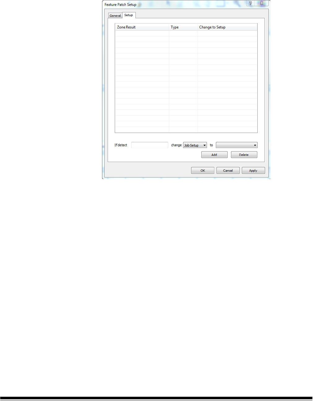
A-61750 November 2016 213
Feature Patch Setup -
Setup tab
After enabling feature patch and setting up a sample image page with a bar
code or OCR zone, you will need to create a rule to follow when the feature
patch is detected. The rules are defined on the Setup tab of the Feature Patch
setup window. The Setup tab has the following options:
If detect — enter the bar code value or OCR text value from the patch page
that you set up on the General tab.
Change — choose Job Setup or Page Setup from the drop-down list.
To — choose a Job Setup or Page Setup name from the drop-down list. When
the patch page is detected, setup will change to the setup you enter in this
field.
Add — once you have defined a rule, the Add button will add it to the
displayed list.
Delete — choose a rule from the displayed list and choose Delete to remove
the selected rule.
OK — saves your settings and closes the dialog box.
CANCEL — discards changes that were not applied to the list, and closes the
dialog box.
APPLY — saves your settings and leaves the dialog box open.

214 A-61750 November 2016
Define a rule Your rule will have a format such as: If detect <value> change <job setup or
page setup> to <desired setup name>.
1. Set up a rule for a patch page using the If detect, change, and to fields.
2. Once the rule is defined, select the Add button to add the rule to the list.
3. Use Apply or OK to save your changes.
4. Create additional rules if needed. If you have multiple kinds of customized
patch sheets, you need a rule for each one.
NOTE: To change a rule, delete it and add a new one.

A-61750 November 2016 215
10 Troubleshooting
Problem solving Occasionally you may encounter a situation with Kodak Capture Pro Software.
Use the chart below as a guide to check possible solutions to help you resolve
the situation before calling Technical Support.
Problem Possible Solution
Conflict found that will prevent OCR
functions and PDF output from working
The conflict is likely caused by an older version of the OmniPage SDK
Toolkit (from Nuance/ScanSoft), Version 12 or earlier, that was installed
on your PC. If the following Nuance DLL files are present in the
Windows\System32 directory on your PC, then this is the cause of the
conflict:
Formatter.dll
Lecsomgr.dll
Prerendering.dll
RecDiag.dll
Rnapi.dll
To resolve the conflict, remove these DLL files from the System32
directory and restart Capture Pro Software.
More recent versions of ScanSoft/Nuance applications (such as
PaperPort and OmniPage) no longer install their DLL files in the
System32 directory, so removing these files should not impact any other
applications that you may be running on your PC.
Cannot open batch If you try to open a batch and this message is displayed, verify that you
have read-write access to the scanned image folder.
System is running slow
Depending on your scanning resolution and feature set, there may be
some modes that do not drive your scanner at full rated speed using the
minimum system hardware requirements. It is recommended that you
increase your CPU speed and system memory.
For optimum performance:
• Pentium IV, 2.8 GHz (or equivalent) CPU
• 2 GB system memory (or higher)
• Hard disk: at least 40 GB (7200 rpm)

216 A-61750 November 2016
Clearing errors The Kodak Capture Pro Batch Process Status window provides information on
batches that you are preparing for output from Kodak Capture Pro Software.
To view the Batch Status window:
•Select Batch>View Batch Output Status.
To clear the errors:
• Click on the Job Name to Clear All Errors or Clear Selected Errors.
Command line login Capture Pro Software will support a login from the command in the form:
Capture.exe/username<username>/password<password>
For example, a user with the username “tester” and password “123465” could
launch Capture Pro Software with the command:
Capture.exe/username tester/password 123465
If the user is using the current Windows user name to log into Capture Pro
Software, then they may launch Capture Pro Software with the command:
Capture.exe/username
Problem Possible Solution
Conflict found or installation problem
that prevents patch code (or bar code)
functions from working
The conflict may be caused by an older version of an AMP release or
toolkit (from All My Papers) that was installed on your PC. If any of the
following AMP DLL files are present in the Windows\System32 directory
on your PC, then this is the cause of the conflict:
amplm.dll
amplib.dll
ampPX.dll
To resolve the conflict, remove these DLL files from the System32
directory and restart Capture Pro Software.
Newly developed System Output
Destinations do not appear in the Job
Setup>Output>System "Send to"
drop-down list
This may be caused by a missing Microsoft Windows component which
is required for newer System Output Destinations to run properly.
To resolve the issue, visit the appropriate Microsoft link below, and follow
the instructions for download and installation:
http://www.microsoft.com/downloads/details.aspx?familyid=200B2FD9-
AE1A-4A14-984D-389C36F85647&displaylang=en
http://www.microsoft.com/downloads/details.aspx?familyid=A5C84275-
3B97-4AB7-A40D-3802B2AF5FC2&displaylang=en

A-61750 November 2016 217
Common messages Following is a list of messages and corrective actions you can take if one of the
following messages is encountered.
Frequently Asked
Questions — Button
Manager
Question: When I am using more than one Kodak Alaris scanning application
(i.e., Smart Touch and Desktop) which one is used with the button on my
Kodak Scanner?
Answer: The Kodak Alaris scanning application that is activated by the button
on your Kodak Scanner varies depending on the operating system running on
the PC your scanner is attached to, the order in which the applications were
launched, and whether or not the user has administrative rights. See the next
question for how to configure your PC for use with the scanner button.
Question: Can I configure my PC so a specific application is used with the
scanner button?
Answer: Yes, this is done by using the scanner’s Properties settings.
1. Login as an administrator.
2. Go to Control Panel>Scanners and Cameras.
3. Select the scanner attached to your PC.
4. Select the Events tab.
5. Configure the scanner button to start the program that you want to use for
that button number.
6. Log off the administrator account.
7. Login as a non-administrator account.
You can assign an application to each individual button number by using this
method. For example, buttons 1 through 4 can be set to activate Desktop and
buttons 5 through 9 can be set to activate Smart Touch.
NOTE: For Windows 7 and Windows 8, you must login as the “super”
administrator.
Messages Probable Cause/Remedy
License code verification code
failed because no hardware key
could be detected.
Kodak Capture Pro Software could not detect a hardware (WIBU) key.
• Be sure the WIBU key is securely inserted into the USB port of your PC.
The batch cannot be opened
because it is currently in use by
another user.
If you are scanning in a multiple-scanner environment and the batch has
already been opened by another workstation, Kodak Capture Pro Software
will not allow you to open the batch until the batch is closed by the other user.
Recognition of bar codes, patch
codes, and OCR is possible with
color (or grayscale) images, but
scanning performance may be
improved if your Page Setup scans
both color (grayscale) and black
and white images, then deletes the
black and white images.
Information. You can use color or grayscale setups for barcode, but it is not
recommended. Click OK on the Information message, close all windows and
select a black and white Page Setup, then go back to the Bar Code Setup and
scan the image.

218 A-61750 November 2016
Question: If I have both Capture Pro Software and Smart Touch installed on
my PC, how can I configure my PC so that Capture Pro Software is always
used when a scanner button is pressed.
Answer: Follow the procedure below:
1. Login as an administrator.
2. Exit Smart Touch and uncheck Run application at Windows startup.
3. Launch Capture Pro Software.
4. Log off the administrator account.
5. Login as a non-administrator account.
NOTE: The same steps will work if you have Capture Desktop installed
instead of Capture Pro Software.
Question: If I have both Capture Pro Software and Smart Touch installed on
my PC, how can I configure my PC so Smart Touch is always used when a
scanner button is pressed?
Answer: Follow the procedure below:
1. Login as an administrator.
2. Launch Smart Touch.
3. Right-click on the scanner icon in the system tray.
4. Select Remove icon.
5. Make sure the Run application at Windows startup checkbox is
checked. If it is not, check the box and exit Smart Touch.
6. Launch Smart Touch again.
7. Log off the administrator account.
8. Login as a non-administrator account.
NOTE: If you are typically logged on as an administrator when using Capture
Pro Software and Smart Touch, then the last application launched will
be the one that is used when a scanner button is pressed.
Question: How does configuring the scanner button from the Properties dialog
box differ from configuring the button from the system tray?
Answer: Each serves a different purpose. When using the scanner’s
Properties dialog box you are instructing the PC which application to activate
when the scanner’s button is pressed. The application activated can depend
on the scanner button number displayed on the scanner.
When using the system tray (by right-clicking on the application icon displayed
in the system tray) to configure the button setup for the application, you are
instructing the application what operation to perform when the button is
pressed (e.g., Scan to PDF, Scan to email, etc.). The operation performed
depends on the button number displayed on the scanner.

A-61750 November 2016 219
Question: Why is the scanner Properties Event dialog box displayed when I
press the scanner button?
Answer: The operating system displays this dialog box when the button is
pressed and none of the Kodak Alaris applications are running. Select an
application listed in the dialog box to associate the scanner button to that
application.
Question: Can the buttons of non-Kodak scanners be configured to use
shortcuts?
Answer: No. The Button Manager, Shortcut Setup only supports Kodak
scanners.
Technical support Support for Kodak Capture Pro Software can be found on the Kodak Alaris
website: www.kodakalaris.com/go/CaptureProSupport. The support pages
provide product-specific information such as access to product upgrade
downloads, drivers, accessories and access to the FAQs (Frequently Asked
Questions) and details of the support options available for Capture Pro
Software available in your country/region.

220 A-61750 November 2016

A-61750 November 2016 221
Appendix A Glossary
Attachment — when scanning a multi-page document, an attachment refers
to those pages that are in addition to the lead or first page of the document.
For instance, when scanning a 3-page document, pages 2 and 3 are
considered attachments.
Auto Crop — automatically removes the border of an image.
Auto Deskew — automatically straightens the image.
Bar code zone — a bar code zone is a section of an image defined as the
location that may contain a barcode. Multiple different locations and
characteristics (e.g., bar code type) may be set up on an image. The bar codes
within these zones may be used for separation or indexing.
Batch — a collection of documents. A job can be used as the basis for
creating many batches (each up to 999999999 documents; essentially
unlimited). Processing a batch means converting the batch to a specific output
format (i.e., single-page TIFF, PDF, LaserFiche, etc.) and sending it to a batch
destination folder/subdirectory. Batches can be processed one by one
or together.
Document — a paper document is a collection of pages; an electronic
document is also a collection of pages, each of which is represented by one or
more images. A document containing many pages is called a multi-page
document (e.g., a file folder or article).
Document index — the document index links search fields (up to 10 search
fields) with the document number of each document. The document index can
be built manually or automatically with bar codes, OCR, mark detection values
or default values.
Dual Stream — also referred to as simultaneous scanning — is the scanner’s
ability to produce both color/grayscale and black and white images
simultaneously without any further processing required by the host computer.
File format — a bit-mapped graphic file format that is usable for color,
grayscale and black and white images.
Grayscale — a range of gray tones that cover the entire visible light spectrum
from white to black.
Image — the scanner converts sides to images. Every image belongs to a
document with a unique document number. Capture Pro Software gives every
image a sequential number inside its document. One document can contain
up to 999999999 (e.g., essentially unlimited) images. Capture Pro Software
distinguishes between an image coming from the front or rear side of a
page. This allows Capture Pro Software to perform side-specific processing
(e.g., deletion of blank rear sides) where appropriate.
Capture Pro Software also distinguishes between color, grayscale, and black
and white images and can perform color/grayscale versus black and white
specific processing.
Example: Document 250 contains two double-sided pages and produces an
electronic document number 250, which contains four images (1-4).

222 A-61750 November 2016
Index file audit — the verifying system that ensures all index values comply
with the input/output format.
Job — Kodak Capture Pro Software is “job” based. A job is a configuration that
defines what to do with a set of documents that you want to scan. For
example, you may use a job to scan all the pages in the scanner’s feeder and
create a single PDF file with the option to type in a name for the PDF file (a
default job supplied with Capture Pro Software called “Scan to PDF”).
A job contains all of the settings related to document capture and can be either
general settings for any type of document or specifically set for a particular
document type (i.e., invoices or personnel records). These settings can include
bar code settings, document or batch separation, index definitions, OCR
settings as well as settings related to the output files you want to create (JPEG,
TIFF, PDF, Searchable PDF, PNG, etc.), or the document management system
you will send the documents to (Microsoft SharePoint, LaserFiche, etc.).
To scan documents in a job, you need to create a batch to hold the scanned
documents, images and data before you output them.
Kodak Capture Pro Software is shipped with three pre-defined jobs.
• Ready to Scan: a simple job setup allowing you to get familiar with Capture
Pro Software and start scanning right away.
• Scan to PDF: similar to Ready to Scan, this job will scan a document and
display the first page and prompt the user to enter a filename. The filename
is used when the documents are output.
• Scan to e-mail: similar to Scan to PDF. When the PDF file is created, the
user’s email account will automatically be opened with the PDF attached
and ready to send to an email recipient.
JPEG (Joint Photographic Experts Group) — a popular standard for
compressing color still images.
ODBC (Open DataBase Connectivity) — a standard database access method
developed by the SQL Access group. This method makes it possible to access
any data from any application, regardless of which database management
system (DBMS) is handling the data.
OCR (Optical Character Recognition) — the process of recognizing printed
characters by a software application.
Output — the processing of the scanned images and delivering them, with any
index data, to the next stage in the document’s lifecycle. Other software
applications may call this the Release process whereby the scanned
documents are “released” to the next step.
Page — a page in paper form is part of a paper document. A page can
produce one image (single-sided page), two images (double-sided page), or
four images (both color and black and white) after scanning. An electronic
page associates all the images produced when the paper page was scanned.

A-61750 November 2016 223
Page Setup (Scanner Settings Profiles) — page setups hold all of the settings
used to tell the scanner how to capture images. These include scan settings
(e.g., Black & White, Grayscale or Color, one-sided or two-sided scanning) and
imaging settings (i.e., rotation, resolution, etc.)
Kodak Capture Pro is installed with many pre-defined settings to capture
images or you can easily create your own custom profiles.
Page setup is a two-stage process:
• First, setup a scanner-specific “scanner profile” in the scanner’s driver which
contains the physical scanning settings. This tells the scanner how to
capture the images (i.e., resolution, front/back, scanner imaging
enhancements, etc.).
• Second, setup a Capture Pro Software Page Setup that contains the
“scanner profile” to use when scanning and any software-related settings for
scanned pages. These include any image rotation (if not supported by the
scanner), blank page removal, image merging (join both front/rear of a
check into a single image file) or image splitting (split an A3 into two A4
images), etc.
Scan Cache — the location where images are stored after being scanned into
a batch and before the batch is processed. By default, the scan cache is
defined to be on the local hard drive (e.g., C:\) of the scanning PC.
Side — one page has two sides, front and rear. With single-sided pages, the
rear is blank.
Simultaneous scanning — see dual stream.
System Output Destination — determines the image format (e.g., TIFF, PDF,
JPEG, PNG) and output destination for a batch that is processed. Included are
the name and output directory structure for image files and index files.
TIFF (Tagged Image File Format) — a bitmapped graphic file format that is
usable for color, grayscale and black and white images.

224 A-61750 November 2016

A-61750 November 2016 225
Appendix B System Requirements
For a successful installation of Kodak Capture Pro Software, review the
following to be sure your system is equipped with the minimum software and
hardware requirements.
Recommended
software and
hardware
Minimum hardware requirements:
• 2.8 GHz processor with at least 2 GB of memory
NOTE: If you are producing Searchable PDF output on the same PC while
scanning into new batches, it is recommended that your PC has a
dual-core processor.
To ensure optimal performance, the following is recommended:
• Dual core processor
• Memory: 4 GB or higher
• Hard disk: at least 40 GB (7200 rpm)
• Monitor resolution: Minimum 1024 x 768
•DVD-ROM drive
NOTE: Depending on your scanning resolution and feature set, there may be
some modes that do not drive your scanner at full rated speed using
the minimum system hardware requirements. It is recommended that
you increase your CPU speed and system memory.
Certified operating
systems
Kodak Capture Pro Software is certified on the following Microsoft Windows
operating systems:
• Windows 7 Professional, Enterprise or Ultimate (x32)
• Windows 7 Professional, Enterprise or Ultimate (x64)
• Windows 8 Professional, Enterprise (x32)
• Windows 8 Professional, Enterprise (x64)
• Windows 10 Professional, Enterprise (x32)
• Windows 10 Professional, Enterprise (x64)
To use Kodak Capture Pro Software with Windows 7, Windows 8 or Windows
10, your scanner must have a Windows 7, Windows 8 or Windows 10 certified
driver. Check with the manufacturer to confirm that your scanner will work with
a Windows 7, Windows 8 or Windows 10 certified driver.
Certified scanners Kodak Capture Pro Software is certified with more than 150 scanners from a
wide range of manufacturers. For a full list of the scanners currently supported
go to www.kodakalaris.com/go/kcsscannersupport
.

226 A-61750 November 2016

A-61750 November 2016 227
Appendix C KC Custom Application, xsd
<?xml version="1.0" encoding="UTF-8"?>
<xs:schema xmlns:xs="http://www.w3.org/2001/XMLSchema"
elementFormDefault="qualified" attributeFormDefault="unqualified">
<xs:element name="KCCustomApplication">
<xs:annotation>
<xs:documentation>Used for validating the XML file created by
KODAK Capture Pro.</xs:documentation>
</xs:annotation>
<xs:complexType>
<xs:all>
<xs:element name="PARAM_LIST">
<xs:complexType>
<xs:choice>
<xs:element name="PARAM" type="xs:string"
minOccurs="0" maxOccurs="unbounded"/>
</xs:choice>
</xs:complexType>
</xs:element>
<xs:element name="BATCH_NAME" type="xs:string"
minOccurs="0"/>
<xs:element name="FILE1_ALL_BATCH_LOCATION" type="xs:string"
minOccurs="0"/>
<xs:element name="FILE1_BW_BATCH_LOCATION" type="xs:string"
minOccurs="0"/>
<xs:element name="FILE1_CG_BATCH_LOCATION" type="xs:string"
minOccurs="0"/>
<xs:element name="FILE1_BATCH_INDEX_FILE" type="xs:string"
minOccurs="0"/>
<xs:element name="FILE1_DOC_INDEX_FILE" type="xs:string"
minOccurs="0"/>
<xs:element name="FILE1_IMAGE_INDEX_FILE" type="xs:string"
minOccurs="0"/>
<xs:element name="FILE2_ALL_BATCH_LOCATION" type="xs:string"
minOccurs="0"/>
<xs:element name="FILE2_BW_BATCH_LOCATION" type="xs:string"
minOccurs="0"/>
<xs:element name="FILE2_CG_BATCH_LOCATION" type="xs:string"
minOccurs="0"/>
<xs:element name="FILE2_BATCH_INDEX_FILE" type="xs:string"
minOccurs="0"/>
<xs:element name="FILE2_DOC_INDEX_FILE" type="xs:string"
minOccurs="0"/>
<xs:element name="FILE2_IMAGE_INDEX_FILE" type="xs:string"
minOccurs="0"/>
<xs:element name="SYSTEM1_BATCH_LOCATION" type="xs:string"
minOccurs="0"/>

228 A-61750 November 2016
<xs:element name="SYSTEM1_OUTPUT_ROOT_PATH" type="xs:string"
minOccurs="0"/>
<xs:element name="SYSTEM1_BATCH_INDEX_FILE" type="xs:string"
minOccurs="0"/>
<xs:element name="SYSTEM2_BATCH_LOCATION" type="xs:string"
minOccurs="0"/>
<xs:element name="SYSTEM2_OUTPUT_ROOT_PATH" type="xs:string"
minOccurs="0"/>
<xs:element name="SYSTEM2_BATCH_INDEX_FILE" type="xs:string"
minOccurs="0"/>
</xs:all>
</xs:complexType>
</xs:element>
</xs:schema>

A-61750 November 2016 229
Appendix D Using Custom Dictionaries
A custom dictionary may be defined and used to improve the accuracy of
recognizing unique or unusual words that appear in your document set. For
example your documents may contain business specific or medical terms not
found in language dictionaries.
To create a custom dictionary:
1. Select the Custom Dictionary Browse button. The Open dialog box will be
displayed. A sample custom dictionary will be created in the folder <current
Job>\User Dictionary. The custom dictionary will be named
“custom.yyyyMMdd.sud.
2. If desired, enter a different file name. The file name must have the
extension sud.
3. Click Open.
4. Navigate to the custom dictionary file just created and open the file with
any text editor.
NOTE: The text editor must be capable of saving the file with UNICODE
encoding.

230 A-61750 November 2016
5. Enter the desired words or phrases as shown in the file, placing a single
item on each line. For example:
[Literal]
Count = 3
Item0 = Hello
Item1 = World
Item2 = 345
NOTE: Be sure that the Count value is set equal to the number of items
you entered.
6. Save the file using UNICODE encoding.
NOTE: If you want to share a custom dictionary among several jobs, you can
place the custom dictionary *.sud file in any common folder. For
example: …\KCS Pro\Job Setup\User Dictionary. Make sure that you
have selected this custom dictionary in each job that needs to use the
dictionary.

A-61750 November 2016 231
Appendix E Network Edition
Kodak Capture Pro Software Network Edition enables Capture Pro
workstations to interoperate with each other using a set of Network Edition
servers for the purpose of:
• Remote Administration which automatically shares setups between
connected workstations
• a centralized License server which enables dongle-free operation of clients
• centralized batch counters
• Remote Output for off loading computer-intensive output jobs to output
servers
Remote
Administration (RA)
Kodak Capture Pro Software maintains its various “setups” (Job, Page, User,
etc.) in files. Kodak Capture Pro Software Network Edition allows workstations
to share a global, common set of setups by replicating these files between
participating workstations. If these workstations do not require setup changes
or access to other Remote Administration functions (i.e., batch counters),
some operations can be performed offline.
All workstations in a Network Edition workgroup share the same setup files.
Local, unique setups that are specific to a workstation are not supported.
Although the Remote Administration is designed for casual use by a small
number of administrators, safeguards are built in to prevent inadvertent data
overwrites by users updating the same setup in parallel.

232 A-61750 November 2016
Initial synchronization When a Capture Pro Software Network Edition client initially starts up, it will
synchronize with its RA server. This may take several minutes.
During synchronization:
• Any setups on the server that do not exist on the client will be copied to the
client.
• Any setups on the client that do not exist on the server will be copied to the
server.
• If a duplicate setup exists, the server’s setup will overwrite the client’s setup.
When this operation is successful, periodic updates will maintain the common
setups across workstations and it is not necessary to resynchronize when the
application restarts.
If any errors occur during synchronization, the client will exit and the operation
will be restarted.
Setup updates Once synchronized, Network Edition clients will periodically poll the RA server
to check for updates.
Each specific setup is versioned and a database is maintained for each client
indicating every setup and current version. If a new setup or newer version of
an existing setup is detected on the server, it will automatically be downloaded
to the client.
Data conflicts Versioning is also used to prevent data conflicts during the creation or update
of a setup. When a user creates or changes a setup, the following occurs:
1. The user opens a Setup dialog box.
2. The system checks to be sure no one is currently changing setups. Since
some files are shared between setup types, only one workstation at a time
is allowed to perform updates. If any setups are open, the user will be
prompted to try again later.
NOTE: An override option is available but is not recommended. This will
allow a user to steal the lock but it may result in data conflicts.
3. The user saves the new or changed setup.
4. The update service verifies that the workstation has the most recent
version of the setup (if it previously existed).
If the service detects that the server has a more recent version, a Data
Conflict error will be returned to the application. Although this is rare, if this
does happen, it is a result of a user stealing the setup or some other
background update that occurred as a side effect of some other
processing. The user can:
• select another name for the setup or discard their changes, or
• exit the Setup window, wait for the conflict to be resolved and reattempt
the change following an update cycle.

A-61750 November 2016 233
5. The update service will lock the setup which prevents other workstations
from modifying it while the upload is in progress. If the update service
cannot obtain a lock (another user is in the process of updating the setup)
a Data Conflict error will result. Remedies for this are the same as
described in Step 2.
6. If no data conflicts occur, the setup will be uploaded to the server which will
then increment the version for the specific setup files.
7. Other workstations will detect the more recent version(s) on the server and
download it.
Although changes are submitted from a client to the server when they are
made, downloading new setups from the server to the client occurs
periodically and is not event-driven. Therefore, a small delay will occur
between the time a new setup is created and the time it is replicated and
becomes visible on other workstations. It is recommended that at least 2
minutes be allowed for this process to occur. During this time, data conflicts
may persist but simply waiting for the update cycle to occur should bring things
back into synch and allow update operations to proceed. Following a data
conflict, it is recommended that users close out any setup windows and reopen
the setup after waiting to allow data refresh to occur.
Deleting and renaming
setups
Currently, setups cannot be deleted or renamed because it is impossible to
detect if other workstations in the NE workgroup have the setup in use. This
may be re-enabled in a future release of Capture Pro Software.
Centralized Batch
counters
The Remote Administration server supports a central batch counting facility,
both at a system level and job level.
These counters are shared throughout the NE workgroup. When a batch is
created, if a batch counter is included in the batch name formula, the NE client
will request the next counter from the RA server and it will be automatically
incremented.
Some changes have been made to the NE client to accommodate this. Since
the counter is global, users can no longer change batch counters when they
create a new batch. The batch name window will be “grayed out”. This implies
that jobs which include batch counters in batch name formulas cannot be used
in off line mode.
In Network Edition, no one can change the system-level batch counters. Job-
level batch counters can still be reset through the job setup; however use
caution when doing this to avoid batch name conflicts.

234 A-61750 November 2016
Remote Output The optional Remote Output server transfers entire batches to remote servers
for output processing. This feature off-loads processor-intensive output tasks
(like creating searchable PDF files) from client workstations. In benchmark
tests, remote output has been demonstrated to improve overall system
throughput significantly for processor-intensive output jobs compared to local
processing or shared folder-based workgroups.
Remote Output is selected on a per-job basis using the Setup menu. Jobs can
be assigned to specific servers, or servers can be selected from a list in round-
robin fashion.
When a Remote Output batch is output:
• the local output processor detects that it is a remote batch, transfers it to the
remote output server, signals the remote server, and sets its local status to
“processed”.
• the Remote Output server processes the batch and updates the batch
information file.
• the Remote Output server detects changes in the status of the remote batch
on the originating client and transfers status information and logs to the
client. If the batch is deleted after processing, it will also be deleted on the
originating workstation. However, the batch history will be maintained on the
Capture Pro Software Server until it is explicitly removed.
If any errors occur during processing, corrections must be made on the
originating workstation and the entire batch resubmitted. No Capture Pro client
user interface is available on the server.
Output server
configuration
Remote output servers are not self configuring. Many job setups are
dependent on the presence of various plug in’s, the existence of particular
paths and directories, user dictionaries, and other optional manually
configured parameters. The system administrator must configure the Remote
Output server so that all necessary support software and other configurations
are in place to support the job mix that is intended to be processed on the
server.
License server The License server provides on-demand licenses to NE client workstations. It
is an optional feature of Network Edition and standard dongle-based licenses
can continue to be used in combination with the other features described in
this section.
To operate in “dongle-free” mode and obtain a license from the License server,
the user only needs to unplug any dongles and restart the Capture Pro client.
Upon startup, if the client does not detect a dongle, it will automatically request
a license from the server.
Licenses are requested and renewed automatically and transparently. A user
will be informed only if a failure occurs.
Upon receiving a license request, the License server will look for an available
license. The License server maintains a set of licenses at various scanner
levels. When the License server receives a license request, it will search the
license table for a license that matches the exact scanner level requested.

A-61750 November 2016 235
• If no license is available, the License server issues the next highest
available license. Licenses are issued in the following rank order: A, B,
Indexing, C, D, DX, E, F, G. Therefore, if all A’s have been issued, a request
for an A license may be fulfilled with a B license or higher.
• Auto Import license requests may result in the issuance of an Auto Import
“Edition” license (which only allows Auto Import) or an E or above (which
allows Auto Import as well as enabling appropriate scanners).
• If none are available, the request will fail.
Once a client (or output server) receives a license it will be automatically
renewed. Administrators can monitor available licenses, when they were
granted, and when they will expire using the Capture Pro Dashboard.
Sometimes if a workstation goes into “sleep” mode a license renewal may fail.
In this event, a message will be displayed informing them that the license
renewal failed, but after clicking OK a new license will be obtained
automatically. Normally, clients renew their licenses transparently in the
background.
Each license is granted for a specific duration. If it is not renewed within this
period, the client will be unable to operate. This duration is currently set to 10
minutes. The client will continue to operate for this interval while issuing
warnings that the license is due to expire.
If a license fails to renew due to sporadic communication failures or other
issues, it should only be necessary to acknowledge any error messages and
the client will automatically obtain a new license. Some errors may require an
application reset.
Fail over Network Edition clients have the ability to “fail over” without reconfiguring
software. If a server fails, an administrator can enable a backup server which
has been pre-configured into each clients’ server map and it will automatically
find the server.
• License server fail over is largely transparent. An initial license renewal
failure will be observed, but after a user clicks OK, the request will
automatically fail over to the next License server on the list. No further user
action is required.
• Remote Administration server fail over is less transparent than License
server fail over. As described above, all workstations in a NE workgroup
share identical setups. When moving to a different server, clients will have to
perform the initial synchronization operation again to bring them into synch
with the new server.
Therefore, when a new server is started up, it should be done with the full
awareness of all participating clients which must all be restarted in order for the
initial synchronization to occur.

236 A-61750 November 2016

A-61750 November 2016 237
Appendix F License Manager
The License Manager is a utility that may be installed and run independently of
Kodak Capture Pro Software. The License Manager is installed with Capture
Pro Software and can be accessed and run by selecting License Manager
from the Help menu or by selecting the shortcut found at Kodak>Kodak
Capture Pro Software. If Kodak Capture Pro Software is not installed on the
computer, License Manager may be downloaded from www.kodakalaris.com/
go/CaptureProDownload. The utility provides a set of functions that may be
used to acquire and manage a license for your Capture Pro Software.
The License Manager is the easiest way to get a license for a workstation
running Capture Pro Software that does not have internet access.
Software Serial Number — displays the software serial number which is used
to identify your license.
Version Number — specifies the Capture Pro Software version that you want
to use. Versions previous to Version 4.0.0 may not be selected.
License Location — specifies the location where your license is installed. For
a typical installation, the location will be C:\Program Files\Kodak\Capture
Pro\System.
License Status — statuses are: Licensed, Temporary License or Not
Licensed. Temporary licenses expire on a predetermined date.
License Request, Release License and Replace License tabs — see the
sections that follow for detailed information and procedures.
Register — allows you to register Capture Pro Software and obtain a
Registration ID. The Registration ID may be used for future installations of
this license or other Capture Pro Software licenses you may own.

238 A-61750 November 2016
Show Hardware ID — displays the hardware ID that is used to identify the
licensed workstation.
Close — closes the License Manager window.
Requesting a license The License Request functions are used to request a license from the Kodak
license server.
Get License — use this option if the workstation to be licensed has internet
access.
Get Trial License — allows you to request a trial license if you do not have a
software serial number.
Request License — if the workstation to be licensed does not have internet
access, select Request License to create a license request file that may be
used to request a license using a computer with internet access. You will be
prompted to enter a location for the license request file.
Upload Request — this function is used on a computer with internet access to
send the license request file to the Kodak license server. You will be prompted
to enter the location of the license request file. If license request is successful,
your license file will be returned to this location.
Install License — this function is used on the workstation without internet
access to install the license retrieved from a computer with internet access.
You will be prompted for the location of the license file.

A-61750 November 2016 239
Following are some examples of when you would use Request License:
Example 1
Scenario: Capture Pro Software is installed on my workstation. I have
purchased an optional feature and need to update my license to enable the
optional feature. My workstation has internet access.
Solution:
1. Select Help>License Manager from the menu bar.
2. From the License Manager window, select the Request License tab and
then select Get License.
Your new license will be retrieved and installed.
Example 2
Scenario: I am installing Capture Pro Software on a workstation without
internet access. During installation the installer has created a license request
file. What do I do now?
Solution:
1. On a different computer with internet access, download the License
Manager tool from the Capture Pro Software download site
(www.kodakalaris.com/go/CaptureProDownload).
2. Install and launch License Manager.
3. From the Request License tab select Upload Request.
4. Browse to the license request file that was created on the workstation
without internet access and upload the file.
Your licence will be returned and stored at the same location where you
browsed to select the licence request file.
5. Move the returned license file to the workstation where you are installing
Capture Pro Software and continue installation.
Example 3
Scenario: Capture Pro Software is installed on my workstation. I have
purchased an optional feature and need to update my license to enable the
optional feature. My workstation does not have internet access.
Solution:
1. Select Help>License Manager from the menu bar.
2. From the License Manager window, select the License Request tab and
then select Request License.
3. Enter the path to where you want the license request file to be saved.
Select Request. A license request file will be created.
4. Move the license request file to a computer with internet access.
5. On the computer with internet access, download the License Manager tool
from the Capture Pro Software download site
(www.kodakalaris.com/go/CaptureProDownload).
6. Install and launch License Manager.

240 A-61750 November 2016
7. From the License Request tab select Upload Request.
8. Browse to the license request file you moved to this computer and select
Upload.
Your license will be returned and stored at the same location where you
browsed to select the license request file.
9. Move the returned license file to the workstation where Capture Pro
Software is running and select Install License from the License Request
tab. You will be prompted to enter the path to the license file you moved to
the workstation.
Release license The Release License functions are used to release the license from the
currently assigned workstation. You must release a license before uninstalling
Capture Pro Software or moving the license to a different workstation.
Release License — if the licensed workstation has internet access, this option
will remove the license from the workstation and make the license available for
a new workstation.
Request Release — if the licensed workstation does not have internet access,
use this option to create a release request file. This file may be moved to a
computer with internet access and sent to the Kodak license server using
Upload Request. You will be prompted to enter a location for the release
request file.
Upload Request — this option is used to release your license by sending the
release request file to the Kodak license server from a computer with internet
access. You will be prompted to enter the location of the release request file.

A-61750 November 2016 241
Following are some examples of when you would use Release License:
Example 1
Scenario: Capture Pro Software is installed on my workstation. I would like to
move Capture Pro Software to a new, faster workstation. My workstation has
internet access.
Solution:
1. Select Help>License Manager from the menu bar.
2. From the License Manager window, select the Release License tab and
then select Release License.
3. Exit Capture Pro Software. Your license will be removed from this
workstation and is now available to be installed on the new workstation.
Example 2
Scenario: Capture Pro Software is installed on my workstation and I need to
reconfigure the workstation (add/remove memory, update the BIOS, change
the Machine Name, replace the mother board, etc.). My workstation has
internet access.
Solution:
1. Select Help>License Manager from the menu bar.
2. From the License Manager window, select the Release License tab and
then select Release License.
3. Exit Capture Pro Software.
4. Reconfigure the workstation as needed.
5. Launch the License Manager tool typically found in the Capture Pro
application folder <drive>: \Program Files\Kodak\Capture
Pro\KCSPLM.exe.
6. From the License Manager window, select the License Request tab and
select Get License. Your new license will be retrieved and installed.
Example 3
Scenario: Capture Pro Software is installed on my workstation and I need to
reconfigure the workstation (add/remove memory, update the BIOS, change
the Machine Name, replace the mother board, etc.). My workstation does not
have internet access.
Solution:
1. Select Help>License Manager from the menu bar.
2. From the License Manager window, select the Release License tab and
then select Request Release. Enter the path to where you want the
release request file to be stored. Select Request.
3. Exit Capture Pro Software.
4. Move the release request file to a computer with internet access.
5. Download the License Manager tool from the Capture Pro Software
download site.

242 A-61750 November 2016
6. Install and launch License Manager.
7. From the Release License tab select Upload Request.
8. Browse to the license request file you moved to this computer and select
Upload.
9. Reconfigure the workstation running Capture Pro Software.
10. When configuration is complete, launch the License Manager tool typically
found in the Capture Pro application folder <drive>: \Program
Files\Kodak\Capture Pro\KCSPLM.exe.
11. Select the License Request tab and then select Request License. Enter
the path to where you want the license request file to be saved. Select
Request. A license request file will be created.
12. Move the license request file to the computer with internet access that has
the License Manager installed.
13. From the License Request tab, select Upload Request.
14. Browse to the license request file you moved to this computer and select
Upload.
15. Move the returned license file to the workstation without internet access
and select the License Request tab and then select Install License. You
will be prompted to enter the path to the license file you moved to this
workstation.
Example 4
Scenario: I have made changes to my workstation hardware configuration and
now when I launch Capture Pro Software I get the message, Invalid license
code. What do I do?
Solution 1:
1. Change the workstation hardware configuration back to the original
settings. If this is not possible, see Solution 2.
2. See Example 2 if you have internet access or Example 3 if your
workstation does not have internet access.

A-61750 November 2016 243
Solution 2:
• If your workstation has internet access:
1. From the Capture Pro installation folder (typically Program
Files>Kodak>Capture Pro), run the License Manager, KCSPLM.exe.
2. From the Replace License tab, select Replace Lost License. A new
license will be retrieved and installed.
• If your workstation does not have internet access:
1. From the Capture Pro installation folder (typically Program
Files>Kodak>Capture Pro), run the License Manager, KCSPLM.exe.
2. From the Replace License tab, select Request Replacement. Enter the
path to where you want the replacement request file to be saved. Select
Request. A license replacement request file will be created.
3. Exit Capture Pro Software.
4. Move the replacement request file to a computer with internet access.
5. On the computer with internet access, download the License Manager
tool from the Capture Pro Software download site.
6. Install and launch License Manager.
7. From the Replace License tab select Upload Request.
8. Browse to the replacement request file you moved to this computer and
select Upload. Your license will be returned and stored at the same
location where you browsed to select the replacement request file.
9. Move the returned license file to the workstation without internet access.
10.On the workstation without internet access, go to the Replace License
tab and select Install License.
11.Browse to the location of the license file you moved to this workstation
and select Install.

244 A-61750 November 2016
Replacing a license The Replace License functions are used to replace an original license that has
been lost due to equipment failure or loss. Replacing a license that is not lost is
a violation of the license agreement and may result in the forfeit of the license.
Replace Lost License — if the replacement workstation has internet access,
this option will retrieve and install a new license for this workstation.
Request Replacement — if the replacement workstation does not have
internet access, use this option to create a license replacement request file.
This file may be moved to a computer with internet access and sent to the
Kodak license server using Upload Request.
Upload Request — this option is used on a computer with internet access to
send the replacement license request file to the Kodak license server.
Install License — this function is used on the workstation without internet
access to install the license retrieved from a computer with internet access.

A-61750 November 2016 245
Following are some examples of when you would use Replace License:
Example 1
Scenario: The hard drive on my Capture Pro Software workstation failed and I
cannot recover the contents. My workstation has internet access. What do I
do?
Solution:
1. Before installing your Capture Pro Software, download the License
Manager tool from the Capture Pro Software download site.
2. Install and launch the License Manager.
3. From the Replace License tab select Replace Lost License. A new
license is retrieved, but is not needed at this time.
4. Download Capture Pro Software from the Capture Pro Software download
site and launch the installer. During installation a copy of your new Capture
Pro Software license will be retrieved from the Kodak license server.
Example 2
Scenario: The hard drive on my Capture Pro Software workstation failed and I
am not able to recover the contents. My workstation does not have internet
access. What do I do?
Solution:
1. Before installing your Capture Pro Software, download the License
Manager tool from the Capture Pro Software download site.
2. Install the License Manager on the workstation that does not have internet
access and launch the License Manager.
3. From the Replace License tab select Request Replacement. Enter the
path to where you want the replacement file to be saved. Select Request.
A license replacement request file will be created.
4. Move the license replacement request file to a computer with internet
access.
5. On the computer with internet access, download the License Manager tool
from the Capture Pro Software download site.
6. Install and launch the License Manager.
7. From the Replace License tab select Upload Request.
8. Browse to the license replacement request file you moved to this computer
and select Upload. Your license will be returned and stored at the same
location where you browsed to select the license replacement request file.
9. Return to the workstation where you want to install Capture Pro Software
and run the Capture Pro Software installer. During installation the installer
will create a license request file.
NOTE: The license request file is not needed as you have already
created a replacement license in Step 8.
10. Move the replacement license file to the workstation where you are
installing Capture Pro Software and continue with the installation.

